SWP1 Series Technical Data
Firmware revision: Rev.2.01.08
Thank you for your purchase of the Yamaha SWP1 series.
Please read this manual carefully, correctly installing the unit and making the proper settings before use.
Make sure to observe the warnings and cautions listed in this manual, in order to use the unit correctly and safely.


Firmware Updates
For stable operations of this L2 switch, we recommend that you apply the latest updates, which include new functionality and bug fixes.
Please confirm your system version when applying updates.
- Use the "show version" command to confirm the system version.
Web GUI Function
The latest firmware for this L2 switch includes the following settings and functions:
- Detailed settings
- VLAN
- MAC address table
- IGMP snooping
- QoS
- EEE
- Management
- Unit settings
- Time settings
- Access management
- Management password
- Maintenance
- Command execution (for details on the commands, refer to the Command Reference)
- Firmware update
- CONFIG file management
- SYSLOG management
- Restart and initialization
- Unit settings
Support Service Center
- Yamaha Pro Audio global website:
http://www.yamahaproaudio.com/ - Yamaha Downloads
http://download.yamaha.com/
- SWP1 Series Technical Data (Basic Functions)
- Maintenance and operation functions
Maintenance and operation functions
- DIP switch control
- MODE switch control
- Boot data management
- Viewing unit information
- Time management
- Firmware update
- List of preset settings
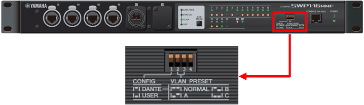
DIP switch control
1 Function Overview
This L2 switch is equipped with a four-switch DIP switch.
Each switch is assigned to its own function. By setting the switches beforehand, the operations of the L2 switch can be changed without sending commands from a PC or making settings using the GUI.
However, the functions assigned to the DIP switches cannot be changed using commands or the GUI settings.
2 Function Details
The functions assigned to the DIP switches are shown below.
The DIP switch settings are reflected in each function when this L2 switch is booted up. If the DIP switch settings are changed after booting up this L2 switch, they will be enabled the next time the unit is booted up.
The DIP switch factory settings are set to all "Up (OFF)".
2.1 DIP switch #1: Select CONFIG mode
The mode for this L2 switch on boot up (defined as "CONFIG mode") can be set to either "DANTE mode" or "USER mode".
DIP switch #1 settings
| Setting position | Content of setting |
|---|---|
| Up (OFF) | The unit will start in DANTE mode. |
| Down (ON) | The unit will start in USER mode. |
- Operation when selecting "DANTE mode"
The preset specified by DIP switches #2 and #3 will always be used when the system boots up.
When the system boots up in DANTE mode, the "copy" or "write" commands cannot be used to save the settings.
However, settings that are necessary for maintenance, such as the IPv4 address, can be saved using the backup-config command. (For details, refer to the Command Reference.)
- Operation when selecting "USER mode"
The preset specified by DIP switches #2 and #3 will be used only on the first time when the system boots up (or after initialization).
When the system boots up in USER mode, the "copy" or "write" commands can be used to save the settings.
In this mode, the data saved by the user can be used.
2.2 DIP switch #2/#3: Select preset
Select the VLAN preset to be used when booting up the system.
The presets will be reflected in the system, depending on the settings of DIP switch #1.
Refer to "Maintenance and operation functions: SWP1 preset setting list" for the specific preset setting values.
DIP switch #2/#3 settings
| Setting position | VLAN preset type | |
|---|---|---|
| #2 | #3 | |
| Up (OFF) | Up (OFF) | Normal |
| Down (ON) | Up (OFF) | A |
| Up (OFF) | Down (ON) | B |
| Down (ON) | Down (ON) | C |
2.3 DIP switch #4
No functions are allocated to this switch at present.
3 Related Commands
The related commands are shown below.
For details, refer to the Command Reference.
List of related commands
| Operations | Operating commands |
|---|---|
| Save setting information | write |
| copy running-config startup-config |
4 Examples of Command Execution
4.1 Save setting information to a Config file
L2SW# write
Building configuration...
[OK]
5 Points of Caution
None
6 Related Documentation
None
MODE switch control
1 Function Overview
This L2 switch displays the LAN/SFP port status using LEDs.
The position of the MODE switch and port LEDs are shown below, using the SWP1-16MMF as an example.
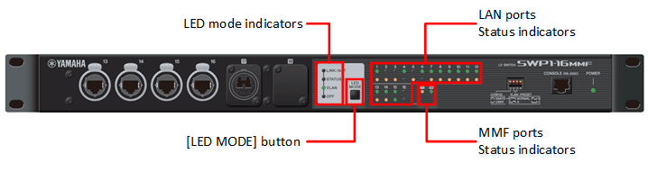
2 Definition of Terms Used
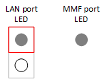
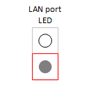
- LED lights: key
The LED lights used in the following explanations are shown below.
LED lights: key

3 Function Details
3.1 Switching between display modes
This L2 switch provides the four display modes shown below.
| Mode name | MODE LED light status | Function overview |
|---|---|---|
| LINK/ACT mode | 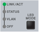 | Shows the link status on the top LAN port LED, and the connection speed on the bottom LED. Only the link status is shown for the SFP ports. |
| STATUS mode | 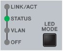 | Shows the loop detection status for the LAN ports. In this mode, the SFP port LED is off. |
| VLAN mode | 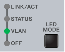 | Shows the VLAN ID set for the LAN port. In this mode, the SFP port LED is off. |
| OFF mode | 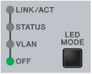 | The LAN/SFP port LED is off, which lowers power consumption. |
Use the MODE switch to switch between display modes.
Display mode switching follows the flow shown below.
- Display mode switching (when the default LED mode is LINK/ACT)
- The display mode after system boot and the display mode after loop resolve depends on the default LED mode settings.
Refer to "3.5 Changing the LED mode after system boot" for details.
- When a loop is detected using the proprietary algorithm, the port LED display automatically switches to STATUS mode.
Even when the MODE switch is pressed in this status, the unit will remain in STATUS mode. (The switch will not function until the loop has been resolved.)
When holding down the MODE switch in this status for three seconds, the loop detection status will be reset, and the display will switch to LINK/ACT mode.
(Refer to *LED display in STATUS mode* for details.)
3.2 LED display in LINK/ACT mode
The port LEDs will display as shown below in LINK/ACT mode.
- LAN/SFP port link status
- LAN port connection speed
The LED display for the link status is shown below.
LAN/SFP port link status: LED display
| Linking down | Linking up | Forwarding data |
|---|---|---|
 (OFF) | 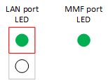 (Lights green) | (Blinks green) |
The LED display for the connection speed is shown below.
LAN port connection speed: LED display
| 10BASE-T | 100BASE-T | 1000BASE-T |
|---|---|---|
 (OFF) | 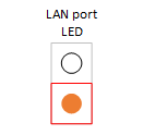 (Lights orange) | 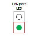 (Lights green) |
3.3 LED display in STATUS mode
In STATUS mode, the port LEDs show the status of loops detected by the proprietary loop detection function. (Only for the LAN port LED)
Four LAN port states are managed using the proprietary loop detection function for this L2 switch.
The port LED light status for the loop detection status of each LAN port is shown below.
Port LED light status for the loop detection status of each LAN port
| Loop detection status | Explanation of detection status | LAN port LED light status |
|---|---|---|
| Loop not detected (Normal) | A loop is not occurring |  (OFF) |
| Loop detected (Blocking) | Communications are being blocked, due to a loop detected between LAN ports in the switch |  (Blinks orange) |
| Loop detected (Detected) | A loop is detected between LAN ports in the switch, but communications are not being blocked due to communications being blocked in the other port |  (OFF) |
| Loop detected (Shutdown) | Since a loop is occurring in the hub connected to a LAN port, the relevant port has been shut down | (Blinks orange) |
- When a loop is detected using the proprietary loop detection function in this L2 switch in any mode besides STATUS, the LAN port LED display is forced to switch to STATUS mode.
In STATUS mode when a loop has been detected, the LEDs will automatically switch to the default LED mode in the following states.
Refer to "3.5 Changing the LED mode after system boot" regarding the default LED mode.
- Loop was resolved
- The MODE switch was pressed down (for three seconds), resetting (clearing) the loop detection status
- The monitoring time (five minutes) has elapsed since shutdown status (the monitoring time cannot be changed at this time)
- After executing the "no shutdown" command in shutdown status, the unit linked up
3.4 LED display in VLAN mode
The port LEDs will display the VLAN association status in VLAN mode, as shown below. (Only for LAN ports)
The port LED light status is shown below.
Port LED light status in VLAN mode
| VLAN association status for LAN port | LAN port LED light status |
|---|---|
| Is not associated with any VLAN |  (OFF) |
| Associated with one VLAN | 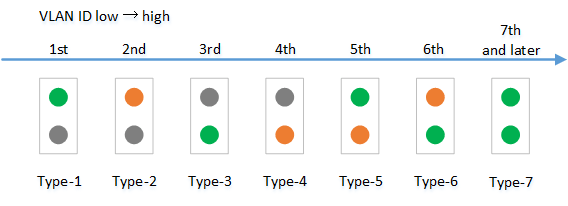 Expressed as one of six specific light patterns, from the newest ID in the VLAN IDs. All VLAN IDs from #7 onwards will be indicated using the same light pattern. |
| Associated with multiple VLANs |  (Both upper and lower port LEDs light up in orange) |
- The default VLAN (VLAN #1) is not shown. It is not counted as an associated VLAN.
- The association status of the VLAN does not depend on the link status of each LAN port. Ports in linkdown status will be shown.
- Only VLAN IDs with associated LAN ports are shown.
When only the VLAN ID is defined (without an associated LAN port), the VLAN ID is not shown.
3.5 Changing the LED mode after system boot
The LED mode after system boot (hereafter called "default LED mode") for this L2 switch can be configured.
The default value for the default LED mode is set to "LINK/ACT mode", but can be changed using the "led-mode default" command.
Use the "show led-mode" command to check the default LED mode and the LED mode currently displayed.
When STATUS mode is cleared during loop detection, the unit will switch to the default LED mode that was set.
4 Related Commands
The related commands are shown below.
For details on the commands, refer to the Command Reference.
List of related commands
| Operations | Operating commands |
|---|---|
| Show LAN/SFP port status | show interface |
| Show setting status of loop detection | show loop-detect |
| Show VLAN information | show vlan brief |
| Default LED mode setting | led-mode default |
| Show LED mode | show led-mode |
5 Examples of Command Execution
5.1 Check LAN/SFP port status
L2SW# show interface
Interface ge1
  Link is UP
  Hardware is Ethernet
  HW addr: 00a0.deae.b818
  ifIndex 1, MRU 1522
  Speed-Duplex: auto(configured), 1000-full(current)
  Auto MDI/MDIX: on
  Interface counter:
    input  packets          : 483
           bytes            : 52551
           multicast packets: 380
    output packets          : 258
           bytes            : 18640
           multicast packets: 252
           broadcast packets: 3
Interface ge2
  Link is DOWN
  Hardware is Ethernet
  HW addr: 00a0.deae.b818
  ifIndex 2, MRU 1522
  Speed-Duplex: auto(configured), -(current)
  Auto MDI/MDIX: on
  Interface counter:
  :
(Shows the status of all LAN/SFP ports.)
5.2 Check LAN/SFP port loop detection status
SWP1# show loop-detect
loop-detect: Enable

port      loop-detect    port-blocking           status
-------------------------------------------------------
ge1            enable(*)        enable           Normal
ge2            enable(*)        enable           Normal
ge3            enable(*)        enable           Normal
ge4            enable(*)        enable           Normal
ge5            enable(*)        enable           Normal
ge6            enable(*)        enable           Normal
ge7            enable(*)        enable           Normal
ge8            enable(*)        enable           Normal
ge9            enable(*)        enable           Normal
ge10           enable(*)        enable           Normal
ge11           enable(*)        enable           Normal
ge12           enable(*)        enable           Normal
ge13           enable(*)        enable           Normal
ge14           enable(*)        enable           Normal
ge15           enable(*)        enable           Normal
ge16           enable(*)        enable           Normal
ge17           enable           enable           Normal
ge18           enable           enable           Normal
-------------------------------------------------------
(*): Indicates that the feature is enabled.
5.3 Check VLAN association status of LAN/SFP port
L2SW# show vlan brief
(u)-Untagged, (t)-Tagged

VLAN ID  Name                            State   Member ports
======= ================================ ======= ======================
1       default                          ACTIVE  ge1(u) ge2(u) ge3(u)
                                                 ge4(u) ge5(u) ge6(u)
                                                 ge7(u) ge8(u) ge9(u)
                                                 ge10(u) ge11(u)
                                                 ge12(u) ge13(u)
                                                 ge14(u) ge15(u)
                                                 ge16(u) ge17(u)
                                                 ge18(u) po1(u)
5.4 Setting the default LED mode
In this example, we will set the default LED mode to OFF mode.
L2SW(config)# led-mode default eco … (Set the default LED mode.)
L2SW(config)# exit
L2SW# show led-mode … (Show the LED mode.)
default mode : eco
current mode : eco
6 Points of Caution
None
7 Related Documentation
- SWP1 Series Technical Data (Basic Functions)
- Maintenance and operation functions
- Boot data management
Boot data management
1 Function Overview
- This L2 switch manages system boot information, as shown on the table below.
System boot information: items managed
Management item Description System boot time Time that the system booted up Run-time firmware update Firmware version currently running, and date generated Reason for boot Reason why the system booted up. The following reasons for boot are recorded: - Boot due to power on
- Reboot due to firmware update
- Reboot due to "reload" command
- Reboot due to lack of memory
- Reboot due to "cold start" command
- Reboot due to kernel panic
This L2 switch stores the current boot information and information on the previous four boots, for a total of five boot records.
If a kernel panic has occurred as a result of a program malfunction or the likes, the stack dump and register dump will be saved, which are useful information for analysis.
2 Related Commands
The related commands are shown below.
For details, refer to the Command Reference.
List of related commands
| Operations | Operating commands |
|---|---|
| Show boot information | show boot |
| Clear boot information | clear boot list |
3 Examples of Command Execution
3.1 Show boot information
- This shows the current boot information.
L2SW>show boot
 Running EXEC: SWP1 Rev.2.01.01 (Mon Sep 14 10:27:13 2015)
Previous EXEC: SWP1 Rev.2.01.01 (Mon Sep 14 10:27:13 2015)
Restart by reload command
- This shows a list of the boot history.
L2SW>show boot list
No. Date       Time     Info
--- ---------- -------- -------------------------------------------------
  0 2015/01/01 00:00:00 Restart by reload command
  1 2015/01/01 00:00:00 Power-on boot
--- ---------- -------- -------------------------------------------------
3.2 Clear boot information
- This clears the boot information.
L2SW# clear boot list
4 Points of Caution
None
5 Related Documentation
None
- SWP1 Series Technical Data (Basic Functions)
- Maintenance and operation functions
- Viewing unit information
Viewing unit information
1 Function Overview
1.1 Show unit information via command
This L2 switch provides the display functions shown in the table below.
List of unit information display items
| Display item | Description | Commands |
|---|---|---|
| Version information | Shows the program version that is operating in this L2 switch. | show version |
| Inventory information | Shows the information for this L2 switch, such as inventory name, model number, and product ID.If an SFP module has been inserted, the inventory information for the module will also be shown. | show inventory |
| Operating information | Shows the operating information for this L2 switch's programs, such as running software information, CPU usage, memory usage, boot time. | show environment |
| Technical support information | Outputs all data relevant to operating information, which is necessary analysis information for technical support. | show tech-support |
1.2 Remote retrieval of technical support information
A TFTP client installed on a PC or other remote terminal can be used to obtain the technical support information (the output results of "show tech-support") from this L2 switch.
Set up a network environment that can be remotely accessed in order to operate this L2 switch's TFTP server, using the steps shown below.
- Decide on the VLAN that will be used for maintenance.
- Set the IPv4 address on the maintenance VLAN. Use the "ip address" command for this setting.
- Permit access from the maintenance VLAN to the TFTP server. Use the "tftp-server interface" command for this setting.
When using a TFTP client, specify "techinfo" for the remote path from which technical support information is obtained.
2 Related Commands
The related commands are shown below.
For details, refer to the Command Reference.
List of related commands
| Operations | Operating commands |
|---|---|
| Shows version information | show version |
| Shows inventory information | show inventory |
| Shows operating information | show environment |
| Shows technical support information | show tech-support |
3 Examples of Command Execution
3.1 Show version information
This checks the version information (as shown below).
- Boot version
- Firmware revision
- MAC address
L2SW>show version
SWP1-16 BootROM Ver.1.00
SWP1-16 Rev.2.01.01 (Mon Sep 14 11:28:38 2015)
Base ethernet MAC Address: 00a0.de00.0000
3.2 Show inventory information
This checks the following inventory information for this unit and for the SFP modules.
- Name (NAME)
- Description (DESCR)
- Vendor Name (Vendor)
- Product ID (PID)
- Version ID (VID)
- Serial number (SN; only for SFP modules)
L2SW>show inventory
NAME: L2 switch
DESCR: SWP1-16
Vendor: Yamaha
PID: SWP1-16
VID: 0000

NAME: SFP1
DESCR: 1000BASE-SX
Vendor: AVAGO
PID: AFBR-5715APZ
VID:
SN: 00000000000

NAME: SFP2
DESCR: 1000BASE-SX
Vendor: AVAGO
PID: AFBR-5715APZ
VID:
SN: 00000000000
3.3 Show operating information
This checks the system operating information (as shown below).
- Boot version
- Firmware revision
- MAC address
- CPU usage ratio
- Memory usage ratio
- CONFIG mode
- VLAN preset (only in DANTE mode)
- Serial baud rate
- Boot time
- Current time
- Elapsed time from boot
L2SW>show environment
SWP1-16 BootROM Ver.1.00
SWP1-16 Rev.2.01.01 (Mon Sep 14 11:28:38 2015)
main=SWP1-16 ver=00 MAC-Address=00a0.de00.0000
CPU:   0%(5sec)   1%(1min)   1%(5min)    Memory:  45% used
Configuration mode: DANTE
VLAN preset: NORMAL
Serial Baudrate: 9600
Boot time: 1970/01/01 00:00:00 +09:00
Current time: 1970/01/01 00:00:00 +09:00
Elapsed time from boot: 0days 00:00:00
3.4 Show technical support information
Shows a list of the results of executing the following commands useful for technical support.
- show running-config
- show environment
- show inventory
- show boot all
- show logging
- show interface
- show frame-counter
- show vlan brief
- show spanning-tree mst detail
- show loop-detect
- show mac-address-table
- show l2ms
- show mls qos queue-counters
- show ddm status
- show errdisable
L2SW# show tech-support
#
# Information for Yamaha Technical Support
#

*** show running-config ***
!
ip domain-lookup
!
spanning-tree mode mstp
!

...

#
# End of Information for Yamaha Technical Support
#
4 Points of Caution
None
5 Related Documentation
None
Time management
1 Function Overview
This L2 switch provides the functions shown below for managing the date and time.
- Manual (user-configured) date/time information setting function
- Automatic date/time setting information function via network
- Time zone setting function
Note that a function to set summertime (DST: Daylight Saving Time) is not provided.
2 Definition of Terms Used
- UTC (Coordinated Universal Time)
This is an official time used when recording worldwide times.
UTC is used as a basis to determine standard time in all countries around the world.
For instance, Japan (JST, or Japan standard time) is nine hours ahead of Coordinated Universal Time, and is thus shown as "+0900 (JST)".
- SNTP (Simple Network Time Protocol)
This is a simple protocol to correct clocks by using SNTP packets.
This protocol is defined in RFC4330.
3 Function Details
3.1 Manually setting the date and time
Use the "clock set" command to directly input the time.
3.2 Automatically setting the date and time
Date and time information is collected from a specified time server, and set in this L2 switch.
Defined in RFC4330, SNTP (Simple Network Time Protocol) is used as a communication protocol.
Only a single time server can be specified, either an IPv4 address, an IPv6 address or an FQDN (Fully Qualified Domain Name).
Port number 123 is used for the SNTP client. (This setting cannot be changed by the user.)
The following two methods for automatically setting the date/time can be selected by using the "ntpdate" command.
- One-shot update (a function to update when a command is inputted)
- Interval update (a function to update in a 1-24-hour cycle from command input)
The time server is set to "ntp.nict.jp" by default, with an interval update cycle of 1 hour.
However, when the default time cannot be set right after booting up the system, the time server will be queried in a one-minute cycle, regardless of the interval cycle time.
The cycle will be corrected to match the interval cycle once the default time settings have been completed.
Synchronization with the time server operates with one sampling (the frequency of replies from the server) and with a timeout of 1 second.
Synchronization is blocked during command execution, and an error message is outputted if a timeout occurs.
3.3 Time zone settings
In order to manage the time for the region considered as the "base of daily life", the "clock timezone" command is used to manage the time zone of the users, and reflect this into the time.
The time zone can be set in ±1 hour increments for Coordinated Universal Time (UTC), from -12 hours to +13 hours.
The default time zone value for this L2 switch is ±0.
4 Related Commands
The related commands are shown below.
For details, refer to the Command Reference.
List of related commands
| Operations | Operating commands |
|---|---|
| Set clock manually | clock set |
| Set time zone | clock timezone |
| Show current time | show clock |
| Set NTP server | ntpdate server |
| Synchronize time from NTP server (one-shot update) | ntpdate oneshot |
| Synchronize time from NTP server (update interval) | ntpdate interval |
| Show NTP server time synchronization settings | show ntpdate |
5 Examples of Command Execution
5.1 Manually setting the time
In this example, the time zone is set to JST (+9:00), and the current time is set to 2014.01.21 15:50:59.
L2SW# configure terminal
L2SW(config)# clock timezone +9:00 … (Sets the time zone.)
L2SW(config)# exit
L2SW# clock set 15:50:59 Jan 21 2014 … (Set the system time.)
L2SW# show clock … (Shows the current time and date.)
15:50:59 JST Tue Jan 21 2014
5.2 Automatically setting the time
In this example, the time zone is set to JST (+9:00), and the NTP server is set to the local time at 192.168.1.1.
Also, the update cycle between the NTP server is changed to once per 24 hours.
L2SW# configure terminal
L2SW(config)# clock timezone +9:00 … (Sets the time zone.)
L2SW(config)# ntpdate server ipv4 192.168.1.1 … (Specify the NTP server.)
L2SW(config)# ntpdate interval 24 … (Set 24 hours as the periodic synchronization time with the NTP server.)
L2SW(config)# exit
L2SW# show clock … (Shows the current time and date.)
15:50:59 JST Tue Jan 21 2014
L2SW(config)# show ntpdate … (Show time synchronization settings from an NTP server.)
NTP server  : 192.168.1.1
adjust time : 2015-02-26 01:00 + interval 24 hours
6 Points of Caution
This L2 switch cannot store date/time information.
For this reason, the date and time are reset to “Jan 1, 1970 00:00:00” when this switch is rebooted (when the time zone is set to “±0.0”).
7 Related Documentation
RFC 4330: Simple Network Time Protocol (SNTP) Version 4 for IPv4, IPv6 and OSI
Firmware update
1 Function Overview
This L2 switch offers the following two firmware update functions, in order to correct program malfunctions and add new functionality.
- Transmitting and applying firmware updates to this L2 switch from a remote terminal, such as a PC
- Built-in HTTP client access to an external HTTP server, to download and apply the latest firmware
These update functions can be used to upgrade or downgrade the version of firmware used on this L2 device.
The unit will operate as follows, regardless of the port lamp display mode for the MODE switches, while the firmware is updating.
- Old firmware being deleted: all LAN port lamps light up green
- New firmware being saved: all LAN port lamps blink green
When the firmware update has been correctly saved, the system will reboot in order to enable the new firmware.
2 Definition of Terms Used
None
3 Function Details
3.1 Update by transmitting the firmware update
This function transmits firmware updates to this L2 switch from a remote terminal, such as a PC, and applies it as boot firmware.
The update process is executed using a TFTP client or the Web GUI.
3.1.1 Using a TFTP client to update the firmware
A TFTP client installed on a PC or other remote terminal can be used to transmit the firmware update to this L2 switch and apply it.
Set up a network environment that can be remotely accessed in order to operate this L2 switch's TFTP server, using the steps shown below.
- Decide on the VLAN that will be used for maintenance.
- Set the IPv4 address on the maintenance VLAN.Use the "ip address" command for this setting.
- Permit access from the maintenance VLAN to the TFTP server.Use the "tftp-server interface" command for this setting.
Follow the rules below when sending the firmware update using the TFTP client.
- Set the transmission mode to "binary mode".
- Specify "exec" as the destination remote path for the firmware update.
If there is no problem with the firmware update that was sent, the firmware update will be saved.
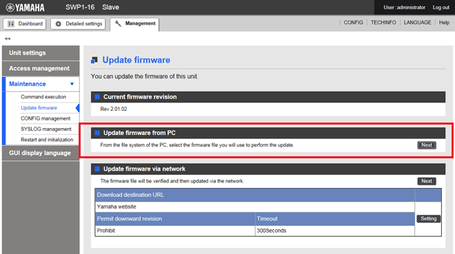
3.1.2. Firmware update by specifying the Web GUI local file
This specifies the firmware update located on the terminal accessing the Web GUI, and applies it to this L2 switch.
This function does not do a version comparison with the existing firmware, and will overwrite the specified firmware regardless of version.
Firmware updates by specifying the local file are done by updating the firmware using "Update firmware from a PC”, accessed from [Maintenance] - [Firmware update] on the Web GUI. (Refer to the part shown in red lines on the screenshot below.)
Refer to the help contents within the GUI for the specific operation method.
Initial screen on the Web GUI for updating firmware using a PC
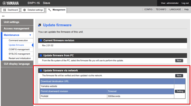
3.2 Using an HTTP client to update the firmware
This method of firmware update uses an HTTP client to obtain the firmware update from a specified URL, and then apply it to this L2 switch.
This function assumes that the firmware version will be upgraded. Downgrading to a previous version will only be permitted if "revision-down" is allowed.
The firmware cannot be rewritten with the same version of firmware.
An HTTP client can be used to update the firmware using the methods below.
- Use the "firmware-update" command from the CLI (Command-line interface)
- Execute the firmware update over the network using the Web GUI
Updating the firmware with an HTTP client is done by using the settings value shown in the table below.
Firmware update using an HTTP client: setting parameters
| Setting parameter | Description |
|---|---|
| Download source URL | Sets the source URL from which the firmware is downloaded. A URL of up to 255 characters in length can be set. The default URL setting is shown below. |
| Permit downward revision | Sets whether the current version of firmware can be downgraded to a previous version. The default value is "Don't allow". Overwriting the firmware with the same version of firmware is not permitted. |
| Timeout | Specifies the timer for monitoring the completion of the processes shown below.
The monitor timer can be set from 100–86,400 sec., and the default value is 300 sec. |
Refer to "5 Examples of Command Execution" or to the "Command Reference" for more information on how to use the "firmware-update" command.
To update firmware over the network using the Web GUI, execute the [Maintenance] - [Firmware update] command from the Web GUI. (Refer to the part shown in red lines on the screenshot below.)
Refer to the help contents within the GUI for the specific operation method.
Initial screen for updating the firmware over the network using the Web GUI
4 Related Commands
The related commands are shown below.
For details, refer to the Command Reference.
List of related commands
| Operations | Operating commands |
|---|---|
| Set firmware update site | firmware-update url |
| Execute firmware update | firmware-update execute |
| Set firmware download timeout duration | firmware-update timeout |
| Permit downward revision | firmware-update revision-down |
| Show firmware update function settings | show firmware-update |
5 Examples of Command Execution
In this example, the firmware update is stored on the local HTTP server, and this L2 switch is set to manage the firmware in order to perform the update.
- This changes the firmware download URL to http://192.168.100.1/swp1.bin.
- The revision-down option is left in disabled mode.
- The timeout value is left at 300 sec.
- The download URL is changed, and the firmware update settings are confirmed.
L2SW(config)# firmware-update url http://192.168.100.1/swp1.bin … (Specify as the firmware download URL.) L2SW(config)# exit L2SW# show firmware-update … (Show the current settings of the firmware update function.) url:http://192.168.100.1/swp1.bin timeout:300 (seconds) revision-down:disable - The firmware update is executed.
L2SW# firmware-update execute … (Update the firmware.) Found the new revision firmware Current Revision: Rev.2.01.01 New Revision: Rev.2.01.02 Downloading... Update to this firmware? (Y/N)y … (Enter y.) Updating... Finish (Reboot automatically.) - Pressing "CTRL+C" during the firmware update process will interrupt the update.
L2SW# firmware-update execute
Found the new revision firmware
Current Revision: Rev.2.01.01
New Revision:     Rev.2.01.02
Downloading...                  … (Enter Ctrl-C.)
^CCanceled the firmware download
6 Points of Caution
None
7 Related Documentation
- SWP1 Series Technical Data (Basic Functions)
- Maintenance and operation functions
- List of preset settings
List of preset settings
SWP1-8/8MMF/16MMF Preset Common Parameters
System-wide common settings
| Category | Setting item | Setting value |
|---|---|---|
| Terminal settings | Number of VTYs | 8 |
| VTY Timeout | 600 sec. | |
| Console Timeout | 600 sec. | |
| Number of lines displayed | 24 | |
| Password | Login password | none |
| Administrator password | none | |
| Encrypt password | not encrypted | |
| Time management | Time zone | UTC±0 |
| NTP server | ntp.nict.jp | |
| NTP update cycle | once per hour | |
| Syslog | Kernel log output | OFF |
| Debug level log output | OFF | |
| Information level log output | ON | |
| Error level log output | ON | |
| SYSLOG server | none | |
| Firmware update | Download URL | http://www.yamahaproaudio.com/ |
| Permit downward revision | don't allow | |
| Timeout | 300 sec. | |
| L2 switching | Automatic MAC address acquisition | enabled |
| Automatic MAC address acquisition ageing time | 300 sec. | |
| Spanning tree | enabled | |
| Proprietary loop detection | enabled | |
| Access control | Telnet server status | run |
| Telnet server access | allow only VLAN #1 | |
| HTTP server status | run | |
| HTTP server access | allow only VLAN #1 | |
| TFTP server access | deny all | |
| Traffic control | QoS | enabled |
| QoS DSCP - transmission queue ID conversion table | DSCP: 8 → transmission queue: 2 DSCP: 46 → transmission queue: 5 DSCP: 56 → transmission queue: 7 Other than above → transmission queue: 0 | |
| Flow control (IEEE 802.3x) threshold value | Threshold start: 80%; Return from restriction: 60% |
Common settings for each LAN/SFP port
| Category | Setting item | Setting value |
|---|---|---|
| Basic settings | Speed/communication mode setting | auto |
| Cross/straight automatic detection | enabled | |
| MRU | 1,522 bytes | |
| Port description | none | |
| EEE | disabled | |
| L2MS | L2MS filter | depends on preset |
| L2 switching | Spanning tree | depends on preset |
| Proprietary loop detection | depends on preset | |
| Traffic control | QoS trust mode | DSCP |
| Flow control (IEEE 802.3x) | disabled | |
| Storm control | disabled |
SWP1-8/8MMF Preset Type: Normal
Settings for the LAN/SFP ports
| Interface | L2MS Filter | LAG (Static) | Port Mode | VLAN | STP | Loop Detection |
|---|---|---|---|---|---|---|
| etherCON1 | Disable | - | Access | 1 (default) | - | ✓ |
| etherCON2 | Disable | - | Access | 1 (default) | - | ✓ |
| etherCON3 | Disable | - | Access | 1 (default) | - | ✓ |
| etherCON4 | Disable | - | Access | 1 (default) | - | ✓ |
| etherCON5 | Disable | - | Access | 1 (default) | - | ✓ |
| etherCON6 | Disable | - | Access | 1 (default) | - | ✓ |
| etherCON7 | Disable | - | Access | 1 (default) | - | ✓ |
| etherCON8 | Disable | - | Access | 1 (default) | - | ✓ |
| opticalCON9 | Disable | sa1 | Access | 1 (default) | ✓ | - |
| opticalCON10 | Disable |
- Settings for the VLAN
- VLAN #1 (for Dante & Control)
- IPv4 Address: DHCP
- IGMP snooping: Enable
- Querier: Enable
- Query Interval: 30 sec
- Fast-Leave: Disable
- Check TTL: Disable
- VLAN #1 (for Dante & Control)
SWP1-8/8MMF Preset Type: A
Settings for the LAN/SFP ports
| Interface | L2MS Filter | LAG (Static) | Port Mode | VLAN | STP | Loop Detection |
|---|---|---|---|---|---|---|
| etherCON1 | Disable | - | Access | 1 (default) | - | ✓ |
| etherCON2 | Disable | - | Access | 1 (default) | - | ✓ |
| etherCON3 | Disable | - | Access | 2 | - | ✓ |
| etherCON4 | Disable | - | Access | 2 | - | ✓ |
| etherCON5 | Disable | - | Access | 1 (default) | - | ✓ |
| etherCON6 | Disable | - | Access | 1 (default) | - | ✓ |
| etherCON7 | Disable | - | Access | 2 | - | ✓ |
| etherCON8 | Disable | - | Access | 2 | - | ✓ |
| opticalCON9 | Disable | sa1 | Trunk | 1 (native), 2 | ✓ | - |
| opticalCON10 | Disable |
- Settings for the VLAN
- VLAN #1 (for Dante)
- IPv4 Address: DHCP
- IGMP snooping: Enable
- Querier: Enable
- Query Interval: 30 sec
- Fast-Leave: Disable
- Check TTL: Disable
- VLAN #2 (for Control)
- IGMP Snooping: Disable
- VLAN #1 (for Dante)
SWP1-8/8MMF Preset Type: B
Settings for the LAN/SFP ports
| Interface | L2MS Filter | LAG (Static) | Port Mode | VLAN | STP | Loop Detection |
|---|---|---|---|---|---|---|
| etherCON1 | Disable | - | Access | 1 (default) | - | ✓ |
| etherCON2 | Disable | - | Access | 1 (default) | - | ✓ |
| etherCON3 | Disable | - | Access | 2 | - | ✓ |
| etherCON4 | Disable | - | Access | 2 | - | ✓ |
| etherCON5 | Disable | - | Access | 1 (default) | - | ✓ |
| etherCON6 | Disable | - | Access | 2 (default) | - | ✓ |
| etherCON7 | Disable | sa1 | Trunk | 1 (native), 2 | ✓ | - |
| etherCON8 | Disable | |||||
| opticalCON9 | Disable | sa2 | Trunk | 1 (native), 2 | ✓ | - |
| opticalCON10 | Disable |
- Settings for the VLAN
- VLAN #1 (for Dante)
- IPv4 Address: DHCP
- IGMP snooping: Enable
- Querier: Enable
- Query Interval: 30 sec
- Fast-Leave: Disable
- Check TTL: Disable
- VLAN #2 (for Control)
- IGMP Snooping: Disable
- VLAN #1 (for Dante)
SWP1-8/8MMF Preset Type: C
Settings for the LAN/SFP ports
| Interface | L2MS Filter | LAG (Static) | Port Mode | VLAN | STP | Loop Detection |
|---|---|---|---|---|---|---|
| etherCON1 | Disable | - | Access | 1 (default) | - | ✓ |
| etherCON2 | Disable | - | Access | 1 (default) | - | ✓ |
| etherCON3 | Enable | - | Access | 2 | - | ✓ |
| etherCON4 | Enable | - | Access | 2 | - | ✓ |
| etherCON5 | Disable | - | Access | 1 (default) | - | ✓ |
| etherCON6 | Disable | - | Access | 1 (default) | - | ✓ |
| etherCON7 | Enable | - | Access | 2 | - | ✓ |
| etherCON8 | Enable | - | Access | 2 | - | ✓ |
| opticalCON9 | Disable | - | Access | 1 (default) | - | ✓ |
| opticalCON10 | Enable | - | Access | 2 | - | ✓ |
- Settings for the VLAN
- VLAN #1 (for Primary Dante & Control)
- IPv4 Address: DHCP
- IGMP snooping: Enable
- Querier: Enable
- Query Interval: 30 sec
- Fast-Leave: Disable
- Check TTL: Disable
- VLAN #2 (for Secondary Dante & Control)
- IGMP Snooping: Enable
- Querier: Enable
- Query Interval: 30 sec
- Fast-Leave: Disable
- Check TTL: Disable
- IGMP Snooping: Enable
- VLAN #1 (for Primary Dante & Control)
SWP1-16MMF Preset Type: Normal
Settings for the LAN/SFP ports
| Interface | L2MS Filter | LAG (Static) | Port Mode | VLAN | STP | Loop Detection |
|---|---|---|---|---|---|---|
| etherCON1 | Disable | - | Access | 1 (default) | - | ✓ |
| etherCON2 | Disable | - | Access | 1 (default) | - | ✓ |
| etherCON3 | Disable | - | Access | 1 (default) | - | ✓ |
| etherCON4 | Disable | - | Access | 1 (default) | - | ✓ |
| etherCON5 | Disable | - | Access | 1 (default) | - | ✓ |
| etherCON6 | Disable | - | Access | 1 (default) | - | ✓ |
| etherCON7 | Disable | - | Access | 1 (default) | - | ✓ |
| etherCON8 | Disable | - | Access | 1 (default) | - | ✓ |
| RJ45 9 | Disable | - | Access | 1 (default) | - | ✓ |
| RJ45 10 | Disable | - | Access | 1 (default) | - | ✓ |
| RJ45 11 | Disable | - | Access | 1 (default) | - | ✓ |
| RJ45 12 | Disable | - | Access | 1 (default) | - | ✓ |
| etherCON13 | Disable | - | Access | 1 (default) | - | ✓ |
| etherCON14 | Disable | - | Access | 1 (default) | - | ✓ |
| etherCON15 | Disable | - | Access | 1 (default) | - | ✓ |
| etherCON16 | Disable | - | Access | 1 (default) | - | ✓ |
| opticalCON17 | Disable | sa1 | Access | 1 (default) | ✓ | - |
| opticalCON18 | Disable |
- Settings for the VLAN
- VLAN #1 (for Dante & Control)
- IPv4 Address: DHCP
- IGMP snooping: Enable
- Querier: Enable
- Query Interval: 30 sec
- Fast-Leave: Disable
- Check TTL: Disable
- VLAN #1 (for Dante & Control)
SWP1-16MMF Preset Type: A
Settings for the LAN/SFP ports
| Interface | L2MS Filter | LAG (Static) | Port Mode | VLAN | STP | Loop Detection |
|---|---|---|---|---|---|---|
| etherCON1 | Disable | - | Access | 1 (default) | - | ✓ |
| etherCON2 | Disable | - | Access | 1 (default) | - | ✓ |
| etherCON3 | Disable | - | Access | 1 (default) | - | ✓ |
| etherCON4 | Disable | - | Access | 1 (default) | - | ✓ |
| etherCON5 | Disable | - | Access | 1 (default) | - | ✓ |
| etherCON6 | Disable | - | Access | 1 (default) | - | ✓ |
| etherCON7 | Disable | - | Access | 2 | - | ✓ |
| etherCON8 | Disable | - | Access | 2 | - | ✓ |
| RJ45 9 | Disable | - | Access | 1 (default) | - | ✓ |
| RJ45 10 | Disable | - | Access | 1 (default) | - | ✓ |
| RJ45 11 | Disable | - | Access | 2 | - | ✓ |
| RJ45 12 | Disable | - | Access | 2 | - | ✓ |
| etherCON13 | Disable | - | Access | 1 (default) | - | ✓ |
| etherCON14 | Disable | - | Access | 1 (default) | - | ✓ |
| etherCON15 | Disable | - | Access | 2 | - | ✓ |
| etherCON16 | Disable | - | Access | 2 | - | ✓ |
| opticalCON17 | Disable | sa1 | Trunk | 1 (native), 2 | ✓ | - |
| opticalCON18 | Disable |
- Settings for the VLAN
- VLAN #1 (for Dante & Control)
- IPv4 Address: DHCP
- IGMP snooping: Enable
- Querier: Enable
- Query Interval: 30 sec
- Fast-Leave: Disable
- Check TTL: Disable
- VLAN #2 (for Control)
- IGMP Snooping: Disable
- VLAN #1 (for Dante & Control)
SWP1-16MMF Preset Type: B
Settings for the LAN/SFP ports
| Interface | L2MS Filter | LAG (Static) | Port Mode | VLAN | STP | Loop Detection |
|---|---|---|---|---|---|---|
| etherCON1 | Disable | - | Access | 1 (default) | - | ✓ |
| etherCON2 | Disable | - | Access | 1 (default) | - | ✓ |
| etherCON3 | Disable | - | Access | 1 (default) | - | ✓ |
| etherCON4 | Disable | - | Access | 1 (default) | - | ✓ |
| etherCON5 | Disable | - | Access | 1 (default) | - | ✓ |
| etherCON6 | Disable | - | Access | 1 (default) | - | ✓ |
| etherCON7 | Disable | - | Access | 2 | - | ✓ |
| etherCON8 | Disable | - | Access | 2 | - | ✓ |
| RJ45 9 | Disable | - | Access | 1 (default) | - | ✓ |
| RJ45 10 | Disable | - | Access | 1 (default) | - | ✓ |
| RJ45 11 | Disable | - | Access | 2 | - | ✓ |
| RJ45 12 | Disable | - | Access | 2 | - | ✓ |
| etherCON13 | Disable | - | Access | 1 (default) | - | ✓ |
| etherCON14 | Disable | - | Access | 2 | - | ✓ |
| etherCON15 | Disable | sa1 | Trunk | 1 (native), 2 | ✓ | - |
| etherCON16 | Disable | |||||
| opticalCON17 | Disable | sa2 | Trunk | 1 (native), 2 | ✓ | - |
| opticalCON18 | Disable |
- Settings for the VLAN
- VLAN #1 (for Dante)
- IPv4 Address: DHCP
- IGMP snooping: Enable
- Query Interval: 30 sec
- Fast-Leave: Disable
- Querier: Enable
- Check TTL: Disable
- VLAN #2 (for Control)
- IGMP Snooping: Disable
- VLAN #1 (for Dante)
SWP1-16MMF Preset Type: C
Settings for the LAN/SFP ports
| Interface | L2MS Filter | LAG (Static) | Port Mode | VLAN | STP | Loop Detection |
|---|---|---|---|---|---|---|
| etherCON1 | Disable | - | Access | 1 (default) | - | ✓ |
| etherCON2 | Disable | - | Access | 1 (default) | - | ✓ |
| etherCON3 | Disable | - | Access | 1 (default) | - | ✓ |
| etherCON4 | Disable | - | Access | 1 (default) | - | ✓ |
| etherCON5 | Enable | - | Access | 2 | - | ✓ |
| etherCON6 | Enable | - | Access | 2 | - | ✓ |
| etherCON7 | Enable | - | Access | 2 | - | ✓ |
| etherCON8 | Enable | - | Access | 2 | - | ✓ |
| RJ45 9 | Disable | - | Access | 1 (default) | - | ✓ |
| RJ45 10 | Disable | - | Access | 1 (default) | - | ✓ |
| RJ45 11 | Enable | - | Access | 2 | - | ✓ |
| RJ45 12 | Enable | - | Access | 2 | - | ✓ |
| etherCON13 | Disable | - | Access | 1 (default) | - | ✓ |
| etherCON14 | Disable | - | Access | 1 (default) | - | ✓ |
| etherCON15 | Enable | - | Access | 2 | - | ✓ |
| etherCON16 | Enable | - | Access | 2 | - | ✓ |
| opticalCON17 | Disable | - | Access | 1 (default) | - | ✓ |
| opticalCON18 | Enable | - | Access | 2 | - | ✓ |
- Settings for the VLAN
- VLAN #1 (for Primary Dante & Control)
- IPv4 Address: DHCP
- IGMP snooping: Enable
- Querier: Enable
- Query Interval: 30 sec
- Fast-Leave: Disable
- Check TTL: Disable
- VLAN #2 (for Secondary Dante & Control)
- IGMP Snooping: Enable
- Querier: Enable
- Query Interval: 30 sec
- Fast-Leave: Disable
- Check TTL: Disable
- IGMP Snooping: Enable
- VLAN #1 (for Primary Dante & Control)
- SWP1 Series Technical Data (Basic Functions)
- IPv4/IPv6
- IPv4/IPv6 common settings
IPv4/IPv6 common settings
1 Function Overview
This L2 switch is compatible with the following IPv4/IPv6 network common environment settings, mainly for the purpose of maintenance (configuring the L2 switch's settings).
- DNS client settings
2 Definition of Terms Used
None
3 Function Details
3.1 DNS client settings
This L2 switch is compatible with DNS (Domain Name System) clients.
If a FQDN (Fully Qualified Domain Name) has been set for an NTP server or a syslog server, an inquiry is made to the DNS server to retrieve the IPv4/IPv6 address.
This L2 switch provides the following, as DNS client control functions.
- Set IP address of the DNS server
- Set default domain name
- Set query domain list
Inquiries to the DNS server are enabled by default, and the settings can be changed by using the "ip domain-lookup" command.
3.1.1 Set IP address of the DNS server
Up to three IP addresses can be set for the DNS server, using the methods shown below.
- Manual setting using the "ip name-server" command
- You can specify a IPv4/IPv6 address.
- Automatic setting via DHCP
This L2 switch always gives priority to the information that was set via commands.
Check the configured DNS servers by using the "show ip name-server" command.
3.1.2 Set default domain
Only one default domain can be set using the methods shown below. The domain length can be set up to 255 characters.
- Manual setting using the "ip domain-name" command
- Automatic setting via DHCP
As with the IP addresses of the DNS server, this L2 switch gives priority to the information that was set via commands.
Check the default domain that was set by using the "show ip domain-name" command.
The use of a default domain is only allowed if there are no listings in the search domain list.
3.1.3 Set query domain list
This L2 switch manages the domain names used when inquiring with the DNS in a query domain list.
Up to six domain names can be set on the query domain list using the methods below.
- Manual setting using the "ip domain-list" command
- Automatic setting via DHCP
As with the IP addresses of the DNS server and the default domain, this L2 switch always gives priority to the information that was set via commands.
The query domain list that has been set can be checked using the "show ip domain-list" command.
Keep in mind that the total number of characters for all domain names registered in the query domain list must be within 255 characters.
4 Related Commands
The related commands are shown below.
For details on the commands, refer to the Command Reference.
List of related commands
| Function types | Operations | Operating commands |
|---|---|---|
| DNS client settings | DNS client settings | ip domain-lookup |
| Set DNS server address | ip name-server | |
| Show DNS server address | show ip name-server | |
| Set default domain name | ip domain-name | |
| Show default domain name | show ip domain-name | |
| Set query domain list | ip domain-list | |
| Show query domain list | show ip domain-list |
5 Examples of Command Execution
5.1 DNS client settings
In this example, the settings are made for the DNS client, and an environment is set up for making inquiries to the DNS.
- The IP addresses for the DNS inquiry destination server are set to 192.168.100.1 and 192.168.100.2.
- The default domain used when making DNS inquiries is set to example.com.
- The DNS inquiry function will be enabled.
L2SW(config)#ip domain-lookup
- Since this is enabled by default, there is no need to make this setting.
- Configure the DNS server.
L2SW(config)#ip name-server 192.168.100.1
L2SW(config)#ip name-server 192.168.100.2
Confirm the DNS server information that was set.
L2SW#show ip name-server
192.168.100.1
192.168.100.2
- Set the default domain name.
L2SW(config)#ip domain-name example.com
Confirm the default domain name that was set.
L2SW#show ip domain-name
example.com
6 Points of Caution
None
7 Related Documentation
None
- SWP1 Series Technical Data (Basic Functions)
- IPv4/IPv6
- IPv4 basic settings
IPv4 basic settings
1 Function Overview
This L2 switch is compatible with the following IPv4 network environment settings, mainly for the purpose of maintenance (configuring the L2 switch's settings).
- IPv4 address settings
- Route information settings
- ARP table settings
2 Definition of Terms Used
- IPv4 link local address
This is an address that is only valid within the same segment, within the range of 169.254.0.0/16 to 169.254.255.255/16.
3 Function Details
3.1 IPv4 address settings
The IPv4 address and subnet mask for a VLAN interface can be set on this L2 switch.
The setting method is compatible with fixed settings and automatic settings via DHCP.
- To set the fixed/automatic IPv4 address, use the "ip address" command.
- The actions when specifying automatic settings via DHCP are shown below.
- The HostName option (option code 12) can be added to the Discover/Request message.
- The lease time requested from the DHCP server is fixed at 72 hours. (The actual lease time will depend on the setting of the DHCP server.)
- If the "no ip address" command is executed with automatic settings, a release message for the IPv4 address obtained is sent to the DHCP server.
- The information obtained from the DHCP server can be checked using the "show dhcp lease" command.
- An IPv4 address can be set for only one VLAN interface.
The IPv4 address that is allocated to a VLAN interface can be checked using the "show ip interface" command.
- The default VLAN (VLAN #1) is set to "automatic settings via DHCP" by default.
3.2 Auto IP function
This L2 switch provides an auto IP function as part of the IPv4 address setting functionality, which automatically generates IPv4 link local addresses based on the MAC address.
The auto IP function only works when an IPv4 address has not been allocated from the DHCP server. (The IPv4 address must be set to "DHCP" as a prerequisite.)
This function confirms whether the automatically-generated IPv4 link local address does not already exist on the network via ARP.
If it has been confirmed that the address does not already exist, the generated address will start to be used.
If the IPv4 address was allocated from the DHCP server after the IPv4 link local address was determined via auto IP, the IPv4 link local address is discarded, and the IP address obtained from the DHCP server is used.
3.3 Route information settings
This L2 switch refers to a routing table when sending syslog messages and when sending out voluntary IPv4 packets as a IPv4 host for NTP-based time adjustments and so on.
This L2 switch uses the following functions to perform the routing table operations.
- Set VLAN interface route information
- Set default gateway
- Set static route information
- Show route information
3.3.1 VLAN interface route information
When setting an IPv4 address on this L2 switch for a VLAN interface, the handling of the network address and VLAN ID is automatically set as route information.
When releasing IPv4 addresses set for the VLAN interface, the above settings will be deleted.
3.3.2 Set default gateway
The destination for IPv4 packets sent to network addresses that are not set in the routing table can be set as the default gateway on this L2 switch.
- To set the default gateway, use the "ip route" command.
- To show the default gateway, use the "show ip route" command.
3.3.3 Set static route information
A static route to the destination network address (the gateway address to which packets will be sent) can be set on this L2 switch.
- Static route information is set using the "ip route" command.
- Static route information is displayed using the "show ip route" command.
3.4 ARP table settings
This L2 switch uses ARP (Address Resolution Protocol) when sending IPv4 packets, and obtains MAC addresses from the IPv4 address.
IPv4 address and MAC address handling is saved in the ARP table under the following specifications.
- ARP entries that are saved in the ARP table manage the following information.
- IPv4 address
- MAC address
- VLAN interface
- Up to 1023 entries are stored in the ARP table, including dynamic and static entries.
- Dynamic entries saved in the ARP table are maintained for 1,200 sec. in the default settings.
The entry timeout value can be changed using the "arp-ageing-timeout" command.
- Dynamic entries saved in the ARP table can be cleared regardless of the timeout value, by using the "clear arp-cache" command.
- Settings for the static entries in the ARP table are made using the "arp" command.
- Use the "show arp" command to check the ARP table.
4 Related Commands
The related commands are shown below.
For details on the commands, refer to the Command Reference.
List of related commands
| Function types | Operations | Operating commands |
|---|---|---|
| IPv4 address settings | IPv4 address settings | ip address |
| Show IPv4 address | show ip interface | |
| Automatically set IP address by DHCP client | ip address dhcp | |
| Show DHCP client status | show dhcp lease | |
| Route information settings | Set default gateway | ip route |
| Show default gateway | show ip route | |
| Set static route information | ip route | |
| Show static route information | show ip route | |
| Show route information | show ip route | |
| ARP table settings | Show ARP table | show arp |
| Set timeout for dynamic entries | arp-ageing-timeout | |
| Clear timeout for dynamic entries | clear arp-cache | |
| Set static entry | arp |
5 Examples of Command Execution
5.1 Setting up a IPv4 network environment (fixed address settings)
In this example, the IPv4 addresses are set on this L2 switch, and an environment is set up for accessing the unit from a remote terminal.
- The maintenance for this L2 switch is done using the default VLAN (VLAN #1).
- The IPv4 address of 192.168.100.240/24 is set for the default VLAN (VLAN #1).
- Permit Web/TFTP access from hosts connected to VLAN #1.
- This sets the address to 192.168.100.240/24 for the default VLAN (VLAN #1).
L2SW# configure terminal
Enter configuration commands, one per line.  End with CNTL/Z.
L2SW(config)# interface vlan0.1
L2SW(config-if)# ip address 192.168.100.240/24
- Check the IPv4 address that was set.
L2SW(config-if)# end
L2SW# show ip interface brief
Interface            IP-Address             Status                Protocol
vlan0.1              192.168.100.240        up                    up
- Set the default VLAN (VLAN #1) to permit access from HTTP servers and TFTP servers.
Access the Web using a remote host after making these settings.L2SW# configure terminal Enter configuration commands, one per line. End with CNTL/Z. L2SW(config)# http-server interface vlan0.1 ... (Allow access to the HTTP server.) L2SW(config)# tftp-server interface vlan0.1 ... (Allow access to the TFTP server.)
6 Points of Caution
None
7 Related Documentation
- SWP1 Series Technical Data (Basic Functions)
- IPv4/IPv6
- IPv6 basic settings
IPv6 basic settings
1 Function Overview
This L2 switch is compatible with the following IPv6 network environment settings, mainly for the purpose of maintenance (configuring the L2 switch's settings).
- IPv6 address settings
- Route information settings
- Neighbor cache table settings
2 Definition of Terms Used
- RA (Router Advertisement)
This is a system for automatically setting address information and network settings for network devices on an IPv6 network to which a router belongs.
- IPv6 address
IPv6 addresses are shown using 128 bits in hexadecimal format. As shown below, a colon (:) is used for every bits, to divide the address into eight fields.
- 2001:02f8:0000:0000:1111:2222:0000:4444
The address can be abbreviated using the rules shown below.
- If the beginning of each field is “0”, this can be abbreviated as “0”.
- If there are four zeroes in a field, the field can be abbreviated using a single zero.
- If there are multiple subsequent fields that contain only zeroes, they can all be abbreviated in one place using “::”.
Applying these rules to the address shown above results in the following address.
- 2001:2f8::1111:2222:0:4444
- IPv6 link local address
This is an address that is only valid within the same segment, within the ranges shown below.
- [Start] FE80:0000:0000:0000:0000:0000:0000:0000
- [End] FE80:0000:0000:0000:FFFF:FFFF:FFFF:FFFF
3 Function Details
3.1 IPv6 address settings
The IPv6 address and prefix length for a VLAN interface can be set on this L2 switch.
The setting method is compatible with fixed settings and automatic settings via RA (router advertisement).
- The IPv6 function must be enabled on the VLAN interface in question to set the IPv6 address.
- Use the “ipv6 enable” command to set the IPv6 function.
- When the IPv6 function is enabled, the IPv6 link local address will automatically be allocated.
- To set the fixed/automatic IPv6 address, use the "ipv6 address" command.
- Only one VLAN interface can be set for an IPv6 address.
IPv6 addresses that can be set for one VLAN interface can be set to either fixed or automatic.
The IPv6 address that is allocated to a VLAN interface can be checked using the "show ipv6 interface" command.
3.2 Route information settings
This L2 switch refers to a routing table when sending syslog messages and when sending out voluntary IPv6 packets as a IPv6 host for NTP-based time adjustments and so on.
This L2 switch uses the following functions to perform the routing table operations.
- Set VLAN interface route information
- Set default gateway
- Set static route information
- Show route information
3.2.1 VLAN interface route information
When setting an IPv6 address on this L2 switch for a VLAN interface, the handling of the network address and VLAN ID is automatically set as route information.
When releasing IPv6 addresses set for the VLAN interface, the above settings will be deleted.
3.2.2 Set default gateway
The destination for IPv6 packets sent to network addresses that are not set in the routing table can be set as the default gateway on this L2 switch.
- To set the default gateway, use the "ipv6 route" command.
- To show the default gateway, use the "show ipv6 route" command.
3.2.3 Set static route information
A static route to the destination network address (the gateway address to which packets will be sent) can be set on this L2 switch.
- Static route information is set using the "ipv6 route" command.
- Static route information is displayed using the "show ipv6 route" command.
3.3 Neighbor cache table settings
This L2 switch uses the Neighbor Discovery protocol when sending IPv6 packets, and obtains MAC addresses from the IPv6 address.
IPv6 address and MAC address handling is saved in the neighbor cache table under the following specifications.
- Neighbor cache entries that are saved in the neighbor cache table manage the following information.
- IPv6 address
- MAC address
- VLAN interface
- Up to 1023 entries are stored in the neighbor cache table, including dynamic and static entries.
- Dynamic entries saved in the neighbor cache table can be cleared by using the "clear ipv6 neighbors" command.
- Settings for the static entries in the neighbor table are made using the "ipv6 neighbor" command.
- Use the "show ipv6 neighbor" command to check the neighbor cache table.
4 Related Commands
The related commands are shown below.
For details on the commands, refer to the Command Reference.
List of related commands
| Function types | Operations | Operating commands |
|---|---|---|
| IPv6 address settings | IPv6 address settings | ipv6 address |
| Show IPv6 address | show ipv6 interface | |
| IPv6 address RA settings | ipv6 address autoconfig | |
| Route information settings | Set default gateway | ipv6 route |
| Show default gateway | show ipv6 route | |
| Set static route information | ipv6 route | |
| Show static route information | show ipv6 route | |
| Show route information | show ipv6 route | |
| Neighbor cache settings | Static neighbor cache entry settings | ipv6 neighbors |
| Show neighbor cache table | show ipv6 neighbors | |
| Clear neighbor cache table | clear ipv6 neighbors |
5 Examples of Command Execution
5.1 Setting up a IPv6 network environment (fixed settings)
In this example, the IPv6 addresses are set manually on this L2 switch, and an environment is set up for accessing the unit from a remote terminal.
- The maintenance for this L2 switch is done using the default VLAN (VLAN #1).
- The IPv6 address for the default VLAN (VLAN #1) is set manually.
- Permit Web/TFTP access from hosts connected to VLAN #1.
- This sets the address to 2001:db8:1::2/64 for the default VLAN (VLAN #1).
L2SW#configure terminal
Enter configuration commands, one per line.  End with CNTL/Z.
L2SW(config)#interface vlan0.1
L2SW(config-if)#ipv6 enable                     ... (Set enable IPv6)
L2SW(config-if)#ip address 2001:db8:1::2/64     ... (Set IPv6 address)
- Confirm the IPv6 address information that was set.
L2SW(config-if)#end L2SW#show ipv6 interface brief Interface IP-Address Status Protocol vlan0.1 2001:db8:1::2/64 up up fe80::2a0:deff:fe:2/64 - Set the default VLAN (VLAN #1) to permit access from HTTP servers and TFTP servers.
Access the Web using a remote host after making these settings.L2SW(config)#http-server interface vlan0.1 ... (Allow access to the HTTP server.) L2SW(config)#tftp-server interface vlan0.1 ... (Allow access to the TFTP server.)
5.2 Setting up a IPv6 network environment (automatic settings using RA)
In this example, the IPv6 addresses are set automatically on this L2 switch, and an environment is set up for accessing the unit from a remote terminal.
- The maintenance for this L2 switch is done using the default VLAN (VLAN #1).
- The IPv6 address for the default VLAN (VLAN #1) is set automatically using RA.
- Permit Web/TFTP access from hosts connected to VLAN #1.
- This sets the RA for the default VLAN (VLAN #1).
L2SW#configure terminal
Enter configuration commands, one per line.  End with CNTL/Z.
L2SW(config)#interface vlan0.1
L2SW(config-if)#ipv6 enable                     ... (Set enable IPv6)
L2SW(config-if)#ip address autoconfig           ... (Set RA for IPv6 address)
- Confirm the IPv6 address information that was acquired via RA.
L2SW(config-if)#end L2SW#show ipv6 interface brief Interface IP-Address Status Protocol vlan0.1 2001:db8::2a0:deff:fe:2/64 up up fe80::2a0:deff:fe:2/64 - Set the default VLAN (VLAN #1) to permit access from HTTP servers and TFTP servers.
Access the Web using a remote host after making these settings.L2SW(config)#http-server interface vlan0.1 ... (Allow access to the HTTP server.) L2SW(config)#tftp-server interface vlan0.1 ... (Allow access to the TFTP server.)
6 Points of Caution
None
7 Related Documentation
- SWP1 Series Technical Data (Basic Functions)
- Remote access functions
- SWP1 Series Technical Data (Basic Functions)
- Remote access functions
- Remote access control
Remote access control
1 Function Overview
This L2 switch offers a function to limit access to the following applications that make network service possible.
- Telnet server
- HTTP server
- TFTP server
- SNMP agent
2 Definition of Terms Used
None
3 Function Details
The following four functions are made possible by limiting access to network service.
- Control whether to leave the service in question running in the background on the system (start/stop control)
- Change reception port number
- Limit access points for services currently running
- Limit the source IP addresses that can access services currently running
The following functions that correspond to each network service are shown in the table below.
Network service access control
| Network service | Start/stop control | Change reception port number | Limit access points | Limit access sources |
|---|---|---|---|---|
| Telnet server | ✓ | ✓ | ✓ | ✓ |
| HTTP server | ✓ | ✓ | ✓ | - |
| TFTP server | - | - | ✓ | - |
| SNMP agent | - | - | ✓ | - |
- Key functions on this L2 switch that always need to run in the background include firmware update, the TFTP server (which is used for running-config and startup-config settings and acquisition), and the SNMP agent (which is used for monitoring the network).
- As a rule, only one network service may run. The same service cannot be running multiple instances.
If the start control is applied to the same service that is currently running, the service will restart.Any connected sessions will be disconnected as a result.
- Limiting access points for network services is done for the VLAN interface.
- Limiting access sources for network services is done by specifying access source IP addresses and whether to permit or deny access.
- The default settings for the network services are shown in the table below.
Network service Start/stop status Reception port number Limit access points Limit access sources Telnet server run 23 Only default VLAN (VLAN #1) permitted Allow all HTTP server run 80 Only default VLAN (VLAN #1) permitted Allow all TFTP server run 69 deny all Allow all SNMP agent run 161 Only default VLAN (VLAN #1) permitted
(for read using SNMPv1 and SNMPv2 only)
Allow all
4 Related Commands
The related commands are shown below.
For details, refer to the Command Reference.
List of related commands
| Network service | Operations | Operating commands |
|---|---|---|
| Telnet server | Start/stop | service telnet-server |
| Change reception port number | service telnet-server (specified as a parameter) | |
| Access control | telnet-server interface | |
| IP address access control | telnet-server access | |
| Show settings | show telnet-server | |
| HTTP server | Start/stop | service http-server |
| Change reception port number | service http-server (specified as a parameter) | |
| Access control | http-server interface | |
| Show settings | show http-server | |
| TFTP server | Access control | tftp-server interface |
| SNMP agent | Access control | snmp-server community |
5 Examples of Command Execution
5.1 Telnet server access control
This example makes it possible to restrict Telnet server access.
The Telnet server reception port is changed to 1024, and access is permitted only from VLAN #1000, which is the maintenance VLAN.
Access to the Telnet server is allowed only for a client from 192.168.100.1.
If you specify telnet-server access, access from IP addresses that do not meet the conditions is denied.
L2SW(config)# service telnet-server 1024 ... (Start the Telnet server with 1024 as the listening port number.)
L2SW(config)# no telnet-server interface vlan0.1 ... (Prohibit access from VLAN #1.)
L2SW(config)# telnet-server interface vlan0.1000 ... (Allow access from VLAN #1000 only.)
L2SW(config)#telnet-server access permit 192.168.100.1 ... (Permit access only from 192.168.100.1)
L2SW(config)# end
L2SW# show telnet-server ... (Show the settings.)
Service:Enable
Port:1024
Interface(vlan):1, 1000
Access:
permit 192.168.100.1
5.2 HTTP server access restriction
This example makes it possible to restrict HTTP server access.
The HTTP server reception port is changed to 8080, and access is permitted only from VLAN #1000, which is the maintenance VLAN.
L2SW(config)# service http-server 8080 ... (Start the Http server with 8080 as the listening port number.)
L2SW(config)# no http-server interface vlan0.1 ... (Prohibit access from VLAN #1.)
L2SW(config)# http-server interface vlan0.1000 ... (Allow access from VLAN #1000 only.)
L2SW(config)# end
L2SW# show http-server ... (Show the settings.)
Service:Enable
Port:8080
5.3 TFTP server access restriction
This example makes it possible to restrict TFTP server access.
Access to the TFTP server is restricted to the maintenance VLAN, VLAN #1 (default VLAN) only.
L2SW(config)# tftp-server interface vlan0.1 ... (Allow access from VLAN #1 only.)
5.4 SNMP agent access restriction
This example makes SNMPv1-based network monitoring possible under the following conditions.
- Set the read-only community name to "public", and specify VLAN #1 (vlan0.1) as the accessible VLAN interface.
- Set the trap destination as "192.168.100.11", and set "snmptrapname" as the trap community name.
L2SW(config)# snmp-server community public ro interface vlan0.1            ... 1
L2SW(config)# snmp-server host 192.168.100.11 traps version 1 snmptrapname ... 2
6 Points of Caution
None
7 Related Documentation
- SWP1 Series Technical Data (Basic Functions)
- Network monitoring
SNMP
1 Function Overview
Setting SNMP (Simple Network Management Protocol) makes it possible to monitor and change network management information for SNMP management software.
In this instance, this L2 switch will operate as an SNMP agent.
This L2 switch is compatible with SNMPv1, SNMPv2c and SNMPv3-based communications.It is also compatible with RFC1213 (MIB-II) and with a private MIB (yamahaSW) as an MIB (Management Information Base).
SNMPv1 and SNMPv2 notifies the recipient of the group name (called a "community"), and communicates only with hosts that belong to that community. In this instance, different community names can be given for the two access modes, read-only and read-write.
In this sense, community names function as a kind of password; but since community names are sent over a network using plain text, they carry inherent security risks. The use of SNMPv3 is recommended when more secure communications are required.
SNMPv3 offers communication content authentication and encryption. SNMPv3 does away with the concept of community and instead uses security models called "USM" (User-based Security Model) and "VACM" (View-based Access Control Model). These models provide a higher level of security.
SNMP messages to notify the status of this L2 switch are called "traps". This L2 switch transmits standard SNMP traps. In SNMPv1, trap requests that do not ask for an answer with the confirmation of receipt from the recipient are specified as the notification message format. However, with SNMPv2 and SNMPv3, either an "inform" request asking for an answer from the recipient, or a trap request can be selected.
On this L2 switch, community names for read-only and transmission traps used by SNMPv1 and SNMPv2c are not determined by default, so you will need to set the appropriate community name. Use caution never to use a login or administrator password when setting a community name, as the community name will be transmitted across the network as plain text.
With the default values, access is impossible in each SNMP version. The transmission host for the trap is not set, so traps will not be sent anywhere.
2 Definition of Terms Used
None
3 Function Details
The main characteristics of each SNMP version and the router setting policies are explained below.
See "5 Examples of Command Execution" later in this text for specific examples of settings.
3.1 SNMPv1
This is authentication between the SNMP manager and agent by using community names.
The controlling device (this L2 switch) is divided and managed by zones called "communities".
Accessing the MIB objects
Use the "snmp-server community" command to permit access using the community name that was set.
Objects can be accessed from a VLAN interface for which an IP address has been set.
SNMP traps
SNMP traps allow for the status of this L2 switch to be sent to the hosts that are configured with the "snmp-server host" command.
The "snmp-server enable trap" command sets what kind of trap is transmitted.
3.2 SNMPv2c
As with SNMPv1, this performs authentication between the SNMP manager and agent by using community names.
The "snmp-server community" command sets the community name used when accessing via SNMPv2c.
The "GetBulk" and "Inform" requests are also now supported from this version.
These requests are used to efficiently retrieve multiple MIB objects, and to confirm replies to notification packets sent from this L2 switch.
Accessing the MIB objects
Use the "snmp-server community" command to permit access using the community name that was set.
Objects can be accessed from a VLAN interface for which an IP address has been set.
SNMP traps
SNMP traps allow for the status of this L2 switch to be sent to the hosts that are configured with the "snmp-server host" command.
Also, the settings of this command can be used to select whether the transmitted message format is a trap or inform request.
Inform requests are used to request confirmation of reply to the recipient.
3.3 SNMPv3
In addition to all of the functions offered in SNMPv2, SNMPv3 offers more robust security functions.
SNMP packets transmitted across the network are authenticated and encrypted, protecting the SNMP packets from eavesdropping, spoofing, falsification, replay attacks and so on, by offering security-related functionality that could not be realized in SNMPv1 and v2C in regard to community names and IP addresses of SNMP managers.
Security
SNMPv3 offers the following security functions.
- USM (User-based Security Model)
USM is a model for maintaining security at the message level. It offers authentication and encryption based on shared key cryptography, and prevents falsification of the message stream.
- Security level
The security level can be specified using the parameter settings for the group to which the user belongs.
The security level combines authentication and encryption, and is classified as shown below.- noAuthNoPriv: no authentication and encryption
- AuthNoPriv: authentication only
- AuthPriv: authentication and encryption
- User authentication
For authentication, HMAC is used in the procedure to authenticate the integrity (whether data has been falsified or not) and the source.
A hash is used in the authentication key to confirm whether the message has been falsified, and whether the sender is the user themselves. Both HMAC-MD5-96 and HMAC-SHA-96 are supported as hash algorithms.
- Encryption
With SNMPv3, SNMP messages are encrypted for the purpose of preventing leakage of managed information.
Both the DES-CBC and AES128-CFB encryption schemes are supported.
The user and membership group name, user authentication method and encryption scheme, as well as the password can be set with the "snmp-server user" command.
The necessary authentication and encryption settings can be made according to the security level specified in the group settings.
- Security level
- VACM (View-based Access Control Model)
VACM is a model for controlling access to SNMP messages.
- Group
With VACM, the access policies mentioned below are defined per group, not per user.
Use the group option of the "snmp-server user" command to set the group(s) that the user will belong to. The MIB views set here that are accessible to the specified groups can be configured.
- MIB view
With SNMPv3, a collection of accessible MIB objects can be defined for each group. When defined, the collection of MIB objects is called the "MIB view". The "MIB view" is expressed as a collected view sub-tree that shows the object ID tree.
Use the "snmp-server view" command to configure the MIB view. Whether the MIB view should be included or excluded in each view sub-tree can be selected.
- Access policies
With VACM, set the MIB view that will permit reading and writing for each group.
Use the "snmp-server group" command to set the group name, security level, and MIB view.
The MIB view will be the view that was configured using the "snmp-server view" command.
- Group
SNMP traps
SNMP traps allow for the status of this L2 switch to be sent to the hosts that are configured with the "snmp-server host" command.
In order to transmit a trap, the "snmp-server user" command must first be used to configure the user.
Also, the settings of this command can be used to select whether the transmitted message format is a trap or inform request.
Inform requests are used to request confirmation of reply to the recipient.
3.4 Private MIB
This switch L2 supports yamahaSW, which is a proprietary private MIB for switch management.
This private MIB allows the obtaining of information for Yamaha's proprietary functions, and for more detailed information about the switch.
Private MIB support is described below.
 yamaha(1.3.6.1.4.1.1182)
  +- yamahaSW(1.3.6.1.4.1.1182.3)
      +- yamahaSWHardware(1.3.6.1.4.1.1182.3.1)
      |   +- yshMemorySize(1.3.6.1.4.1.1182.3.1.2)      (read-only)
      |   |    Memory size
      |   +- yshFlashROMSize(1.3.6.1.4.1.1182.3.1.3)    (read-only)
      |   |     FlashROM size
      |   +- yshMemoryUtil(1.3.6.1.4.1.1182.3.1.4)      (read-only)
      |   |     Memory usage ratio
      |   +- yshCpuUtil5sec(1.3.6.1.4.1.1182.3.1.5)     (read-only)
      |   |     CPU usage ratio (5-second average)
      |   +- yshCpuUtil1min(1.3.6.1.4.1.1182.3.1.6)     (read-only)
      |   |     CPU usage ratio (1-minute average)
      |   +- yshCpuUtil5min(1.3.6.1.4.1.1182.3.1.7)     (read-only)
      |         CPU usage ratio (5-minute average)
      |
      +- yamahaSWFirmware(1.3.6.1.4.1.1182.3.2)
      |   +- ysfConfigFile(1.3.6.1.4.1.1182.3.2.2)      (read-only)
      |   |     Startup config
      |   +- ysfRevision(1.3.6.1.4.1.1182.3.2.3)        (read-only)
      |   |     Firmware version
      |   +- ysfUpTime(1.3.6.1.4.1.1182.3.2.4)          (read-only)
      |   |     Elapsed time from boot
      |   +- ysfRestart(1.3.6.1.4.1.1182.3.2.11)        (read-write)
      |         System restart
      |
      +- yamahaSWL2ms(1.3.6.1.4.1.1182.3.5)
      |   +- yamahaSWL2ms(1.3.6.1.4.1.1182.3.5.0) Trap
      |   |   +- ysl2msFindSlave(1.3.6.1.4.1.1182.3.5.0.1)
      |   |   |    Switch detection trap
      |   |   +- ysl2msDetectDown(1.3.6.1.4.1.1182.3.5.0.2)
      |   |        Switch removal trap
      |   |
      |   +- ysl2msNumber(1.3.6.1.4.1.1182.3.5.1)       (read-only) * Use only trap notification
      |   |     Number of switches that can be recognized
      |   |
      |   +- ysl2msEnableTrap(1.3.6.1.4.1.1182.3.5.2)
      |   |     Set L2MS trap notification
      |   |
      |   +- ysl2msTable(1.3.6.1.4.1.1182.3.5.3)
      |       +- ysl2msEntry(1.3.6.1.4.1.1182.3.5.3.1) { ysl2msIndex }
      |       +- ysl2msIndex(1.3.6.1.4.1.1182.3.5.3.1.1)               (not-accessible) * Use only trap notification
      |       |     * Since the device names will not necessarily be unambiguous
      |       +- ysl2msProduct(1.3.6.1.4.1.1182.3.5.3.1.2)             (read-only) * Use only trap notification
      |       |     Model of device
      |       +- ysl2msPhysAddress(1.3.6.1.4.1.1182.3.5.3.1.5)         (read-only) * Use only trap notification
      |       |     MAC address of device
      |       +- ysl2msRoute(1.3.6.1.4.1.1182.3.5.3.1.11)              (read-only) * Use only trap notification
      |             Route information
      |
      +- yamahaSWErrDisable(1.3.6.1.4.1.1182.3.6)
          +- yamahaSWErrDisable(1.3.6.1.4.1.1182.3.6.0) Trap
          |   +- ywedTrap(1.3.6.1.4.1.1182.3.6.0.1)
          |         Trap for Error Disable state
          |
          +- ysedConfigTable(1.3.6.1.4.1.1182.3.6.1)
          |   +- ysedConfigEntry(1.3.6.1.4.1.1182.3.6.1.1) { ysedConfigIndex }
          |       +- ysedConfigIndex(1.3.6.1.4.1.1182.3.6.1.1.1)               (not-accessible)
          |       +- ysedConfigFunction(1.3.6.1.4.1.1182.3.6.1.1.2)            (read-only)
          |       |     Functions for which Error Disable is enabled
          |       +- ysedConfigAutoRecovery(1.3.6.1.4.1.1182.3.6.1.1.3)        (read-only)
          |       |     Setting for automatic recovery from Error Disable state
          |       +- ysedConfigRecoveryInterval(1.3.6.1.4.1.1182.3.6.1.1.4)    (read-only)
          |             Frequency (seconds) at which to attempt automatic recovery from Error Disable state
          |
          +- ysedEnableTrap(1.3.6.1.4.1.1182.3.6.2)                            (read-write)
          |     Setting for trap notification of Error Disable state
          |
          +- ysedIfTable(1.3.6.1.4.1.1182.3.6.3)
              +- ysedIfEntry(1.3.6.1.4.1.1182.3.6.3.1)
                  +- ysedIfIndex(1.3.6.1.4.1.1182.3.6.3.1.1)                   (not-accessible)
                  +- ysedIfStatus(1.3.6.1.4.1.1182.3.6.3.1.2)                  (read-only)
                        Error Disable state of port
4 Related Commands
The related commands are shown below.
For details on the commands, refer to the Command Reference.
List of related commands
| Operations | Operating commands |
|---|---|
| Set host that receives SNMP notifications | snmp-server host |
| Set notification type to transmit | snmp-server enable trap |
| Set system contact | snmp-server contact |
| Set system location | snmp-server location |
| Set SNMP community | snmp-server community |
| Set SNMP view | snmp-server view |
| Set SNMP group | snmp-server group |
| Set SNMP user | snmp-server user |
| Show SNMP community information | show snmp community |
| Show SNMP view settings | show snmp view |
| Show SNMP group settings | show snmp group |
| Show SNMP user settings | show snmp user |
5 Examples of Command Execution
5.1 SNMPv1 setting example
This example makes SNMPv1-based network monitoring possible under the following conditions.
- Set the read-only community name to "public", and specify VLAN #1 (vlan0.1) as the accessible VLAN interface.
- Set the trap destination as "192.168.100.11", and set "snmptrapname" as the trap community name.
L2SW(config)# snmp-server community public ro interface vlan0.1            ... 1
L2SW(config)# snmp-server host 192.168.100.11 traps version 1 snmptrapname ... 2
5.2 SNMPv2c setting example
This example makes SNMPv2c-based network monitoring possible under the following conditions.
- Set the read-write community name to "private", and specify VLAN #1 as the accessible VLAN interface.
- Specify the notification message destination as "192.168.100.12", the notification type as "inform" request format, and the notification destination community name as "snmpinformsname".
L2SW(config)# snmp-server community private rw interface vlan0.1                 ...1
L2SW(config)# snmp-server host 192.168.100.12 informs version 2c snmpinformsname ...2
5.3 SNMPv3 setting example
This example makes SNMPv3-based network monitoring possible under the following conditions.
- Specify the view that shows the internet node (1.3.6.1) and below as "most".
- Specify the view that shows the mib-2 node (1.3.6.1.2.1) and below as "standard".
- Create the user group "admins", and grant users belonging to the "admins" group full access rights to the "most" view.
- Create the user group "users", and grant users belonging to the "users" group read access rights to the "standard" view.
- Create an "admin1" user that belongs to the "admins" group.
Set the password to "passwd1234", using the "HMAC-SHA-96" authentication algorithm.
Set the encryption password to "passwd1234", using the "AES128-CFB" encryption algorithm. - Create an "user1" user that belongs to the "users” group.
Set the password to "passwd5678", using the "HMAC-SHA-96" authentication algorithm. - Send notifications in trap format (without response confirmation) to 192.168.10.3.
- Send notifications in inform request format to 192.168.20.3.
L2SW(config)# snmp-server view most 1.3.6.1 include                                  ... 1
L2SW(config)# snmp-server view standard 1.3.6.1.2.1 include                          ... 2
L2SW(config)# snmp-server group admins priv read most write most                     ... 3
L2SW(config)# snmp-server group users auth read standard                             ... 4
L2SW(config)# snmp-server user admin1 admins auth sha passwd1234 priv aes passwd1234 ... 5
L2SW(config)# snmp-server user user1 users auth sha passwd5678                       ... 6
L2SW(config)# snmp-server host 192.168.10.13 traps version 3 priv admin1             ... 7
L2SW(config)# snmp-server host 192.168.20.13 informs version 3 priv admin1           ... 8
6 Points of Caution
- Check the SNMP version that can be used with the SNMP manager beforehand.It is necessary to configure this L2 switch in accordance with the SNMP version that will be used.
- This L2 switch is not compatible with the following functions related to SNMPv3.
- Proxy function
- Access to MIB objects after the SNMPv2 subtree (1.3.6.1.6).Changing SNMPv3-related settings via SNMP is also not supported.
- The commands below will fail when reverting to a previous version (before Rev.2.01.04).As a result, the acquisition settings for MIB variables cannot be performed using SNMP.
- snmp-server community COMMUNITY RO_RW [interface IFNAME]
7 Related Documentation
None
- SWP1 Series Technical Data (Basic Functions)
- LAN/SFP port control
- SWP1 Series Technical Data (Basic Functions)
- LAN/SFP port control
- Basic interface settings
Basic interface settings
1 Function Overview
This chapter explains the basic interface functions of this L2 switch.
2 Definition of Terms Used
None
3 Function Details
3.1 Interface types
This L2 switch can handle the five interface types shown in the table below.
Interface list
| Interface types | Interface ID | Description |
|---|---|---|
| LAN port | ge | This is the physical port for this L2 switch. There are two types, a fixed LAN port and a removable SFP port. Continuing from ge, this interface is expressed by the port numbers that are printed on the unit. Specifying LAN port #1: ge1 |
| SFP port | ||
| VLAN interface | vlan | This is a user-defined VLAN. This interface is expressed by vlan followed by "bridge ID (fixed at 0)" + "." + "VLAN ID". Specifying VLAN1: vlan0.1 |
| Static logical interface | sa | This is the user-defined link aggregation. Multiple LAN/SFP ports can be grouped together and used as one interface. Continuing after "sa" or "po", this interface uses "logical link IDs". Specifying the LACP logical interface for logical link ID #1: po1 |
| LACP logical interface | po |
3.2 Interface control
The interface on this L2 switch can be controlled as shown in the table below.
Interface control items
| Control items | Commands | Description |
|---|---|---|
| Set description | description | Sets the description text for the applicable interface. |
| Enable/disable | shutdown | Enables/disables the interface. |
| Communication speed/communication mode | speed-duplex | Sets the communication speed and communication mode for the interface. (Select from the following values.)
|
| MRU | mru | Sets the maximum frame size that can be received by the interface, within a range of 64–10,240 bytes. |
| Cross/straight automatic detection (Auto MDI/MDI-X function) | mdix | This function automatically detects the connection port type (MDI or MDI-X), allowing for interconnection without relying on the cable type (cross or straight). |
| Speed downshift | - | This function automatically drops the speed and tries to link, when a LAN cable is connected for which 1000BASE-T cannot be used. This function is always enabled for LAN ports. (Cannot be disabled.) |
| EEE | power | Sets whether EEE (Energy-Efficient Ethernet) is used. This is standardized for IEEE 802.3az. |
Command control of the interface is performed as shown on the table below.
Interface control functionality chart
| Interface name | Set description | Enable/disable | Communication speed/communication mode | MRU | Cross/straight automatic detection | EEE |
|---|---|---|---|---|---|---|
| LAN port | ✓ | ✓ | ✓ | ✓ | ✓ | ✓ |
| SFP port | ✓ | ✓ | ✓ (*1) | ✓ | - | - |
| VLAN interface | ✓ | - | - | - | - | - |
| Static logical interface | ✓ | ✓ | - | - | - | - |
| LACP logical interface | ✓ | ✓ | - | - | - | - |
*1: Communication speed/communication mode settings for SFP ports are set to either auto negotiation or to 1000Mbps/full duplex.
3.3 LAN/SFP port defaults
Below are the settings used to make the LAN/SFP on this L2 switch function as an L2 switch by default.
- All LAN/SFP ports belong to the default bridge (bridge ID #0).
The bridge ID cannot be changed using this L2 switch.
- The default state of the LAN/SFP ports are determined according to the presets when first booting the unit up. (Refer to Maintenance and operation functions:List of preset settings.)
3.4 Port mirroring
This L2 switch provides a port mirroring function, which copies the data traffic from a selected LAN/SFP port to another specified port.
The communication status can be analyzed by collecting the copied packets.
This L2 switch can be used to set a mirror port, making all other LAN/SFP port allocable as "monitor ports".
The monitoring direction (transmit/receive, transmit only, receive only) can be selected for the monitor ports.
The "mirror" command can be used to set the port mirroring.
The mirror port setting is disabled by default.
3.5 Frame counter
This L2 switch counts the number of frames transmitted/received for each LAN/SFP port. (This is called a "frame counter".)
The frame counter can be referred to with the "show frame counter" command.
The table below shows the display items for the frame counter and their maximum values.
Received frame counter display items
| Display item | Description | Maximum value |
|---|---|---|
| Octets | Number of octets received | 18,446,744,073,709,551,615 |
| Packets (*1) | Number of packets received | 34,359,738,360 |
| Broadcast packets (*2) | Number of broadcast packets received | 4,294,967,295 |
| Multicast packets (*2) | Number of multicast packets received | 4,294,967,295 |
| Unicast packets (*2) | Number of unicast packets received | 4,294,967,295 |
| Undersize packets (*2) | Number of undersize packets received (packets smaller than 64 octets) | 4,294,967,295 |
| Oversize packets (*2) | Number of oversize packets received (packets 1,523 octets or larger (*3)) | 4,294,967,295 |
| Fragments (*2) | Number of fragment packets received (packets smaller than 64 octets with abnormal CRC) | 4,294,967,295 |
| Jabbers (*2) | Number of jabber packets received (packets 1,523 octets or larger with abnormal CRC(*3)) | 4,294,967,295 |
| FCS errors (*2) | Number of FCS error packets received | 4,294,967,295 |
| RX errors | Number of reception errors | 4,294,967,295 |
| Drop Packets (*4) | Number of packets dropped from the reception buffer | 4,294,967,295 |
(*1): The packet value is the total of the (*2) packets.
(*3): This will change, depending on the MRU set for the LAN/SFP port.
(*4): This is shown only if flow control is enabled in the system.
Transmitted frame counter display items
| Display item | Description | Maximum value |
|---|---|---|
| Octets | Number of octets transmitted | 18,446,744,073,709,551,615 |
| Packets (*1) | Number of packets transmitted | 12,884,901,885 |
| Broadcast packets (*2) | Number of broadcast packets transmitted | 4,294,967,295 |
| Multicast packets (*2) | Number of multicast packets transmitted | 4,294,967,295 |
| Unicast packets (*2) | Number of unicast packets received | 4,294,967,295 |
| TX errors | Number of transmission errors | 4,294,967,295 |
| Collisions | Number of collision occurrences | 4,294,967,295 |
| Drop Packets (*3) | Number of tail-dropped transmission packets | 4,294,967,295 |
(*1): The packet value is the total of the (*2) packets.
(*3): This is shown only if flow control is disabled in the system.
Transmitted/received frame counter display items
| Display item | Description | Maximum value |
|---|---|---|
| 64 octet packets | Number of packets with 64 octet length transmitted/received | 4,294,967,295 |
| 65–127 octet packets | Number of packets with 65–127 octet length transmitted/received | 4,294,967,295 |
| 128–255 octet packets | Number of packets with 128–255 octet length transmitted/received | 4,294,967,295 |
| 256–511 octet packets | Number of packets with 256–511 octet length transmitted/received | 4,294,967,295 |
| 512–1,023 octet packets | Number of packets with 512–1,023 octet length transmitted/received | 4,294,967,295 |
| 1,024–MAX octet packets | Number of packets with 1,024–maximum octet length (*1) transmitted/received | 4,294,967,295 |
(*1): This will change, depending on the MRU set for the LAN/SFP port.
The frame counter can be deleted by using the "clear counters" command.
Use the "show interface" command that shows the status of the LAN/SFP port, in order to display information on the number of frames transmitted/received.
The information displayed is based on the frame counter information.
The number of frames transmitted/received that is displayed using the "show interface" command and how the frame counter is handled are shown below.
Number of frames transmitted/received that is displayed using the "show interface" command, and how the frame counter is handled
| Display item | Information on the frame counter referred to | |
|---|---|---|
| input | packets | Received frame counter packets |
| bytes | Received frame counter octets | |
| multicast packets | Received frame counter multicast packets | |
| drop packets (*1) | Received frame counter drop packets | |
| output | packets | Transmitted frame counter packets |
| bytes | Transmitted frame counter octets | |
| multicast packets | Transmitted frame counter multicast packets | |
| broadcast packets | Transmitted frame counter broadcast packets | |
| drop packets (*1) | Transmitted frame counter drop packets | |
(*1): If flow control is enabled in the system, this shows only the received information. If it is disabled, this shows only the transmitted information.
4 Related Commands
The related commands are shown below.
For details, refer to the Command Reference.
Basic interface functions: list of related commands
| Operations | Operating commands |
|---|---|
| Set description | description |
| Shutdown | shutdown |
| Set communication speed and communication mode | speed-duplex |
| Set MRU | mru |
| Set Cross/straight automatic detection | mdix auto |
| Set EEE | power efficient-ethernet auto |
| Show EEE capabilities | show eee capabilities |
| Show EEE status | show eee status |
| Set port mirroring | mirror |
| Show mirroring port status | show mirror |
| Show interface status | show interface |
| Show VLAN information for LAN/SFP port | show interface switchport info |
| Show frame counter | show frame-counter |
| Clear frame counters | clear counters |
| Show SFP status | show ddm status |
5 Examples of Command Execution
5.1 Basic LAN port settings
Some examples of basic LAN port settings are shown below.
For details on how to make the settings, refer to the Command Reference.
- Set the description text for LAN port #1 (ge1).
L2SW(config)# interface ge1
L2SW(config-if)# description Connected to rtx1200-router
- Disable LAN port #1 (ge1).
L2SW(config)# interface ge1
L2SW(config-if)# shutdown
- Enable LAN port #1 (ge1).
L2SW(config)# interface ge1
L2SW(config-if)# no shutdown
- Set the communication speed and communication mode for LAN port #1 (ge1) to 100Mbps/Full.
L2SW(config)# interface ge1
L2SW(config-if)# speed-duplex 100-full
5.2 Mirroring settings
In this example, we will set LAN port #1 to monitor the frames transmitted/received by LAN port #4 and the frames transmitted by LAN port #5.
The roles of the ports are shown below.
- Mirror port: LAN port #1 (ge1)
- Monitor ports: LAN port #4 (ge4), LAN port #5 (ge5)
- Set the monitor port for mirror port LAN port #1 (ge1).
L2SW(config)# interface ge1
L2SW(config-if)# mirror interface ge4 direction both     ... (Mirror the transmitted and received frames.)
L2SW(config-if)# mirror interface ge5 direction transmit ... (Mirror the transmitted frames.)
- Confirm the mirroring settings.
L2SW# show mirror
Mirror Test Port Name: ge1 ... (Setting of "ge1 - ge4".)
Mirror option: Enabled
Mirror direction: both
Monitored Port Name: ge4
Mirror Test Port Name: ge1 ... (Setting of "ge1 - ge5".)
Mirror option: Enabled
Mirror direction: transmit
Monitored Port Name: ge5
5.3 Show LAN/SFP port information
- Confirm the status of LAN port #1 (ge1).
L2SW# show interface ge1
Interface ge1
  Link is UP
  Hardware is Ethernet
  HW addr: 00a0.deae.b89f
  Description: Connected to router
  ifIndex 1, MRU 1522
  Speed-Duplex: auto(configured), 1000-full(current)
  Auto MDI/MDIX: on
  Interface counter:
    input  packets          : 320
           bytes            : 25875
           multicast packets: 301
    output packets          : 628
           bytes            : 129895
           multicast packets: 628
           broadcast packets: 0
           drop packets     : 0
6 Points of Caution
The received frame counter drop packets and transmitted frame counter drop packets functions are supported by Revision 2.01.07 and later versions.
7 Related Documentation
None
- SWP1 Series Technical Data (Basic Functions)
- LAN/SFP port control
- Link aggregation
Link aggregation
1 Function Overview
Link aggregation is a function used to combine multiple LAN/SFP ports that connect network devices, and handle them as a single logical interface.
Link aggregation is a technology that is useful when multiple communications occur.Communications can be distributed by using a load balance function within the combined lines.
If one LAN/SFP port fails within the lines that were combined using link aggregation, and communications cannot be made, the other ports will continue communicating.
Link aggregation function overview
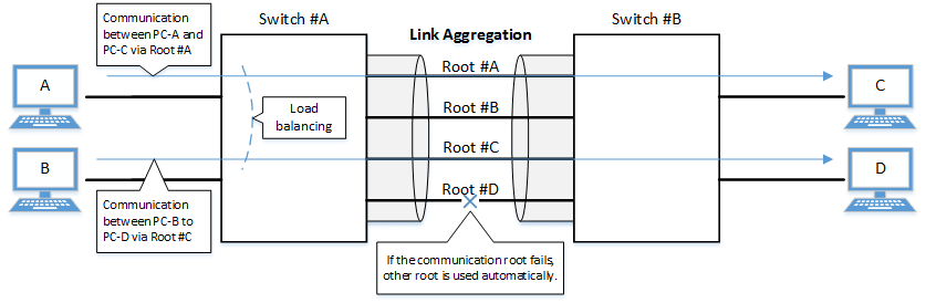
The link aggregation functions in this L2 switch are shown below.
Link aggregation functions
| Functions provided | Contents |
|---|---|
| Static link aggregation | Link aggregation for manually setting the LAN/SFP ports to combine. This begins to operate as a logical interface when the LAN/SFP ports link up. |
| LACP link aggregation | Link aggregation that uses LACP to combine the LAN/SFP ports. This begins to operate as a logical interface when the negotiation via LACP between the connected devices is successful. |
2 Definition of Terms Used
- LACP
Abbreviation for "Link Aggregation Control Protocol". This is a technology standardized in IEEE802.3ad,
and is also called EtherChannel.
- Load balance
This is a function to distribute forwarded frames between the LAN/SFP ports that are associated with the logical interface.
As a distribution rule, the L2/L3/L4 information within frames is used.
3 Function Details
3.1 Static/LACP link aggregation: common specifications
The common specifications for the static/LACP link aggregation functions of this L2 switch are shown below.
- The link aggregation on this L2 switch can be defined for 127 interfaces, including both static and LACP.
- The settings shown below must be the same for each of the LAN/SFP ports contained within.
(The MRU settings can contain different ports, but we recommend that the ports be contained with the same settings.)
- Communication speed/communication mode
If auto negotiation is enabled, only the same port that was used in the contained ports for the initial negotiation results will be contained.
- Port mode (access/trunk [including native VLAN settings])
- Associated VLAN
- Communication speed/communication mode
- The following operations are performed when a LAN/SFP port is associated with a logical interface.
- LAN/SFP ports that are linked up will be linked down.
The logical interface's default value will be set to "shutdown", in order to safely integrate the logical interface into the system.
- MSTP settings will be discarded and will revert to their defaults.
When dissociating a LAN/SFP port from the logical link, the MSTP settings for the relevant port will revert to their defaults as well.
- LAN/SFP ports that are linked up will be linked down.
- The following operations can be performed for the logical interface.
- Add description text ("description" command)
- Enable/disable the interface ("shutdown" command)
- Another LAN/SFP port cannot be associated with a logical interface in operation.
To associate a LAN/SFP port, make sure to shut down the logical interface before associating.
- LAN/SFP ports that are associated with a logical interface that is in operation cannot be removed.
When dissociating a LAN/SFP port, make sure to shut down the logical interface before dissociating.
LAN/SFP ports that have been dissociated from a logical interface will be in shutdown mode.Enable the ports as necessary (using "no shutdown").
- Load balance settings can be made on the logical interface.The rules that can be set for this are shown below.
The default value when defining a logical interface is the destination IP address.
- Destination MAC address
- Source MAC address
- Destination/source MAC address
- Destination IP address
- Source IP address
- Destination/source IP address
- Destination port number
- Source port number
- Destination/source port number
3.2 Static link aggregation
The operating specifications for static link aggregation are shown below.
- An interface number from 1–12 can be assigned to the static logical interface.
- Use the "static-channel-group" command to associate a LAN/SFP port with a static logical link interface.
A single static logical interface can be associated with up to eight LAN/SFP ports.
- When associating a LAN/SFP port with an interface number for which there is no static logical interface, a new logical interface will be generated.
- When the associated port no longer exists as a result of removing a LAN/SFP port from a static logical interface, the relevant logical interface will be deleted.
- Use the "show static-channel-group" command to show the static logical link interface's status.
3.3 LACP link aggregation
The operating specifications for LACP link aggregation are shown below.
Refer to "3.1 Static/LACP link aggregation: common specifications" for the common specifications of static link aggregation.
- An interface number from 1–127 can be assigned to the LACP logical interface.
- Use the "channel-group" command to associate a LAN/SFP port with an LACP logical link interface.
A single LACP logical interface can be associated with up to 12 LAN/SFP ports.
- When associating an LAN/SFP, specify the following operating modes. (It is recommended to specify "active mode".)
- Active mode
The LACP frame will be voluntarily transmitted, and negotiation with the opposing device's port will begin.
- Passive mode
The LACP frame will not be voluntarily transmitted, but will instead be transmitted when a frame is received from the opposing device.
- Active mode
- When associating a LAN/SFP port with an interface number for which there is no LACP logical interface, a new logical interface will be generated.
- When the associated port no longer exists as a result of removing a LAN/SFP port from an LACP logical interface, the relevant logical interface will be deleted.
- When associating an LAN/SFP, specify the following operating modes. (It is recommended to specify "active mode".)
- When there are eight or more LAN/SFP ports to combine in the LACP, these eight ports can be combined as an LACP, but any more than eight ports will become listening ports, to be used in case of failure.
The combined LAN/SFP ports are determined using the following priority.
- Smaller LACP port priority values are given priority.
- If the LACP port priority values are identical, the smaller interface numbers are given priority.
- The parameters that influence the operations of the LACP logical interface are shown below.
- LACP timeout
LACP timeout indicates the down time that was determined, when an LACP frame has not been received from the opposing device.
Specify either "Long" (90 sec.) or "Short" (3 sec.) using the "lacp timeout" command.
The LACP timeout value is stored in the LACP frame and transmitted to the opposing device.
The opposing device that received the frame will transmit the LACP frames it has stored at intervals equaling 1/3 of the LACP timeout value.
The default value when the logical interface is generated is "Long (90 sec.)".
- LACP system priority
The LACP system priority is used when deciding which device will control the logical interface, when communicating with the opposing device.
The device with the highest combined system priority exchanged with the opposing device and MAC address (together called the "system ID") is selected.
The LAN/SFP port associated with the logical interface that is to be enabled (active) is determined for the selected device.
The LACP system priority can be specified from a range of 1–65,535 by the "lacp system-priority" command. (Lower numbers have higher priority.)
The default value when the logical interface is generated is set to 32,768 (0x8000).
- LACP port priority
LACP port priority is used to control active/standby for the LAN/SFP ports that are associated with the logical interface.
When there are more LAN/SFP ports associated to the logical interface than the 8-port maximum, the port status is controlled based on a combination of the LACP port priority and the port number (which is called "port ID").
The port status is controlled based on a combination of the LACP port priority and the port number (which is called "port ID").
The LACP port priority can be specified from a range of 1–65,535 by the "lacp port-priority" command. (Lower numbers have higher priority.)
The default value when the logical interface is generated is set to 32,768 (0x8000).
- LACP timeout
- Use the "show etherchannel" command to show the LACP logical interface status.
4 Related Commands
The related commands are shown below.
For details on the commands, refer to the Command Reference.
List of related commands
| Operations | Operating commands |
|---|---|
| Set the static logical interface | static-channel-group |
| Show the static logical interface status | show static-channel-group |
| Set the LACP logical interface | channel-group |
| Set LACP system priority | lacp system-priority |
| Show LACP system priority | show lacp sys-id |
| Set LACP port priority | lacp port-priority |
| Set LACP timeout | lacp timeout |
| Clear LACP packet counter | clear lacp |
| Show LACP packet counter | show lacp-counter |
| Show the status of the LACP logical interface | show etherchannel |
| Show the protocol status of the LACP logical interface | show etherchannel status |
| Set load balance function rules | port-channel load-balance |
5 Examples of Command Execution
5.1 Setting the static logical interface
In this example, we will set link aggregation to use four LAN ports, in order to communicate between L2 switches.
Static logical interface setting example
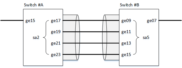
- Static link aggregation is set to static.
The logical interface numbers are set to switch A: #2 and switch B: #5.
- The LAN ports associated with the logical interface are all access ports, and are associated with the VLAN #1000.
- Define [switch A] VLAN #1000, and associate it with LAN ports (#15, #17, #19, #21, #23).
Together with this, associate LAN ports (#17, #19, #21, #23) with the logical interface #2.
L2SW(config)# vlan database ... (Set valan 1000)
L2SW(config-vlan)# vlan 1000
L2SW(config-vlan)# exit
L2SW(config)# interface ge15 ... (Set LAN port #15.)
L2SW(config-if)# switchport access vlan 1000 ... (Sets the VLAN #1000 that is associated as an access port.)
L2SW(config-if)# interface ge17 ... (Set LAN port #17.)
L2SW(config-if)# switchport access vlan 1000 ... (Sets the VLAN #1000 that is associated as an access port.)
L2SW(config-if)# static-channel-group 2 ... (Associate with static logical interface #2.)
L2SW(config-if)# interface ge19
L2SW(config-if)# switchport access vlan 1000
L2SW(config-if)# static-channel-group 2
L2SW(config-if)# interface ge21
L2SW(config-if)# switchport access vlan 1000
L2SW(config-if)# static-channel-group 2
L2SW(config-if)# interface ge23
L2SW(config-if)# switchport access vlan 1000
L2SW(config-if)# static-channel-group 2
- Confirm the setting status of [switch A] logical interface #2.
L2SW# show static-channel-group
% Static Aggregator: sa2
% Member:
   ge17
   ge19
   ge21
   ge23
- Define [switch B] VLAN #1000, and associate it with LAN ports (#07, #09, #11, #13, #15).
Together with this, associate LAN ports (#09, #11, #13, #15) with the logical interface #5.
L2SW(config)# vlan database
L2SW(config-vlan)# vlan 1000
L2SW(config-vlan)# exit
L2SW(config)# interface ge7
L2SW(config-if)# switchport access vlan 1000
L2SW(config-if)# interface ge9
L2SW(config-if)# switchport access vlan 1000
L2SW(config-if)# static-channel-group 5
L2SW(config-if)# interface ge11
L2SW(config-if)# switchport access vlan 1000
L2SW(config-if)# static-channel-group 5
L2SW(config-if)# interface ge13
L2SW(config-if)# switchport access vlan 1000
L2SW(config-if)# static-channel-group 5
L2SW(config-if)# interface ge15
L2SW(config-if)# switchport access vlan 1000
L2SW(config-if)# static-channel-group 5
- Confirm the setting status of [switch B] logical interface #5.
L2SW# show static-channel-group
% Static Aggregator: sa5
% Member:
   ge9
   ge11
   ge13
   ge15
- Enable [switch A] logical interface.
L2SW(config)# interface sa2 ... (Set for logical interface #2.)
L2SW(config-if)# no shutdown ... (Enable logical interface.)
- Enable [switch B] logical interface.
L2SW(config)# interface sa5 ... (Set for logical interface #5.)
L2SW(config-if)# no shutdown ... (Enable logical interface.)
- Confirm the setting status of [switch A] logical interface.
L2SW# show interface sa2 Interface sa2 Link is UP ... (Link status is up.) Hardware is AGGREGATE HW addr: (not set) ifIndex 66, MRU 1522 Interface counter: input packets : 1020 bytes : 102432 multicast packets: 1020 output packets : 15 bytes : 1845 multicast packets: 15 broadcast packets: 0 drop packets : 0 - Confirm the setting status of [switch B] logical interface.
L2SW# show interface sa5
Interface sa5
  Link is UP
  Hardware is AGGREGATE
  HW addr: (not set)
  ifIndex 69, MRU 1522
  Interface counter:
    input  packets          : 24
           bytes            : 2952
           multicast packets: 24
    output packets          : 2109
           bytes            : 211698
           multicast packets: 2109
           broadcast packets: 0
           drop packets     : 0
5.2 Setting the LACP logical interface
In this example, we will set link aggregation to use four LAN ports, in order to communicate between L2 switches.
LACP logical interface setting example
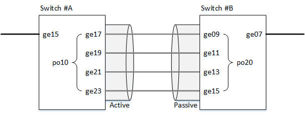
- Use LACP for link aggregation.
The logical interface numbers are set to switch A: #10 and switch B: #20.
Set the switch A logical interface to active status, and the switch B logical interface to passive status.
- The LAN ports associated with the logical interface are all access ports, and are associated with the VLAN #1000.
- For load balance, set the destination/source IP address.
- Define [switch A] VLAN #1000, and associate it with LAN ports (#15, #17, #19, #21, #23).
Together with this, associate LAN ports (#17, #19, #21, #23) in active status with the logical interface #10.
The logical interface at this point in time will be in shutdown mode.
L2SW(config)# vlan database
L2SW(config-vlan)# vlan 1000 ... (Set VLAN #1000.)
L2SW(config-vlan)# exit
L2SW(config)# interface ge15
L2SW(config-if)# switchport access vlan 1000 ... (Sets the VLAN #1000 that is associated as an access port.)
L2SW(config-if)# interface ge17
L2SW(config-if)# switchport access vlan 1000 ... (Sets the VLAN #1000 that is associated as an access port.)
L2SW(config-if)# channel-group 10 mode active ... (Associate in ACTIVE mode with LACP logical interface #10.)
L2SW(config-if)# interface ge19
L2SW(config-if)# switchport access vlan 1000
L2SW(config-if)# channel-group 10 mode active
L2SW(config-if)# interface ge21
L2SW(config-if)# switchport access vlan 1000
L2SW(config-if)# channel-group 10 mode active
L2SW(config-if)# interface ge23
L2SW(config-if)# switchport access vlan 1000
L2SW(config-if)# channel-group 10 mode active
- Confirm the setting status of [switch A] logical interface #10.
L2SW# show etherchannel % Lacp Aggregator: po10 % Member: ge17 ge19 ge21 ge23 L2SW# show lacp sys-id ... (Check the LACP system ID: Default setting value(0x8000).) % System 8000,00-a0-de-ae-b9-1f L2SW# show interface po10 Interface po10 Link is DOWN ... (Link status is down.) Hardware is AGGREGATE HW addr: (not set) ifIndex 138, MRU 1522 Interface counter: input packets : 0 bytes : 0 multicast packets: 0 output packets : 0 bytes : 0 multicast packets: 0 broadcast packets: 0 drop packets : 0 - Define [switch A] VLAN #1000, and associate it with LAN ports (#07, #09, #11, #13, #15).
Together with this, associate LAN ports (#09, #11, #13, #15) in passive status with the logical interface #20.
The logical interface at this point in time will be in shutdown mode.
L2SW(config)# vlan database
L2SW(config-vlan)# vlan 1000 ... (Set valan 1000)
L2SW(config-vlan)# exit
L2SW(config)# interface ge7
L2SW(config-if)# switchport access vlan 1000 ... (Sets the VLAN #1000 that is associated as an access port.)
L2SW(config-if)# interface ge9
L2SW(config-if)# switchport access vlan 1000 ... (Sets the VLAN #1000 that is associated as an access port.)
L2SW(config-if)# channel-group 20 mode passive ... (Associate in PASSIVE mode with LACP logical interface #20.)
L2SW(config-if)# interface ge11
L2SW(config-if)# switchport access vlan 1000
L2SW(config-if)# channel-group 20 mode passive
L2SW(config-if)# interface ge13
L2SW(config-if)# switchport access vlan 1000
L2SW(config-if)# channel-group 20 mode passive
L2SW(config-if)# interface ge15
L2SW(config-if)# switchport access vlan 1000
L2SW(config-if)# channel-group 20 mode passive
- Confirm the setting status of [switch B] logical interface #20.
L2SW# show etherchannel % Lacp Aggregator: po20 % Member: ge9 ge11 ge13 ge15 L2SW# show lacp sys-id ... (Check the LACP system ID: Default setting value(0x8000).) % System 8000,00-a0-de-ae-b8-7e L2SW# show interface po20 Interface po20 Link is DOWN ... (Link status is down.) Hardware is AGGREGATE HW addr: (not set) ifIndex 148, MRU 1522 Interface counter: input packets : 0 bytes : 0 multicast packets: 0 output packets : 0 bytes : 0 multicast packets: 0 broadcast packets: 0 drop packets : 0 - Set the load balance of [switch A] logical interface #10 in the destination/source IP address, and enable.
L2SW(config)# interface po10 ... (Set for logical interface #10.)
L2SW(config-if)# port-channel load-labance src-dst-ip ... (Set the load balance function for the logical interface.)
L2SW(config-if)# no shutdown ... (Enable logical interface.)
- Set the load balance of [switch B] logical interface #20 in the destination/source IP address, and enable.
L2SW(config)# interface po20 ... (Set for logical interface #20.)
L2SW(config-if)# port-channel load-labance src-dst-ip ... (Set the load balance function for the logical interface.)
L2SW(config-if)# no shutdown ... (Enable logical interface.)
- Confirm the setting status of [switch A] logical interface.
Link up and confirm whether frames are being sent and received.
L2SW# show interface po10 Interface po10 Link is UP Hardware is AGGREGATE HW addr: (not set) ifIndex 138, MRU 1522 Interface counter: input packets : 560 bytes : 58239 multicast packets: 560 output packets : 98 bytes : 12474 multicast packets: 98 broadcast packets: 0 drop packets : 0 L2SW# L2SW# show lacp-counter % Traffic statistics Port LACPDUs Marker Pckt err Sent Recv Sent Recv Sent Recv % Aggregator po10 1000000 ge17 50 47 0 0 0 0 ge19 49 46 0 0 0 0 ge21 49 46 0 0 0 0 ge23 49 46 0 0 0 0 - Confirm the setting status of [switch B] logical interface.
Link up and confirm whether frames are being sent and received.
L2SW# show interface po20
Interface po20
  Link is UP
  Hardware is AGGREGATE
  HW addr: (not set)
  ifIndex 148, MRU 1522
  Interface counter:
    input  packets          : 78
           bytes            : 9914
           multicast packets: 78
    output packets          : 438
           bytes            : 45604
           multicast packets: 438
           broadcast packets: 0
           drop packets     : 0
L2SW#
L2SW# show lacp-counter
% Traffic statistics
Port       LACPDUs         Marker         Pckt err
        Sent    Recv    Sent    Recv    Sent    Recv
% Aggregator po20 1000000
ge9      55      57      0       0       0       0
ge11     54      56      0       0       0       0
ge13     54      56      0       0       0       0
ge15     54      56      0       0       0       0
6 Points of Caution
Ports that belong to a private VLAN cannot be combined as a link aggregation logical interface (host ports only).
7 Related Documentation
- SWP1 Series Technical Data (Basic Functions)
- LAN/SFP port control
- Port authentication functions
Port authentication functions
1 Function Overview
Port authentication is a function that authenticates devices or users for each LAN/SFP port.
This authenticates a device connected to the LAN/SFP port, and permits LAN access only for devices that succeeded in authenticating.
Devices that are not yet authenticated or that failed to authenticate can be denied access to the LAN, or permitted to access only a specific VLAN.
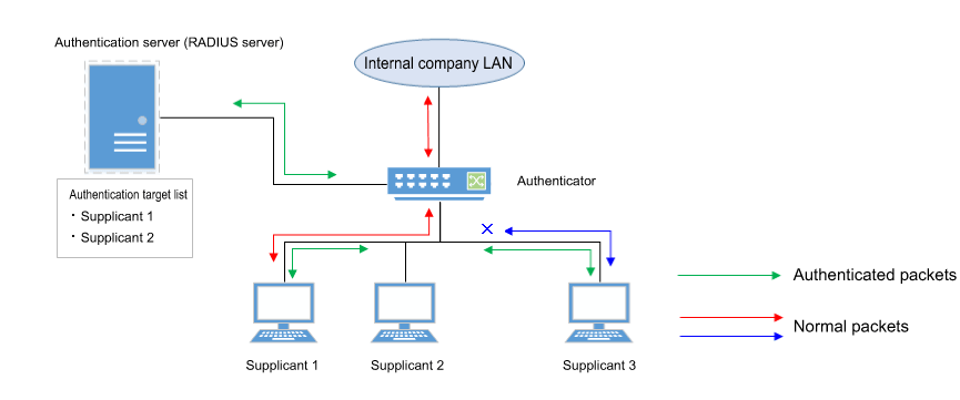
2 Definition of Terms Used
- IEEE 802.1X
The authentication standard used when connecting to the LAN.
- Authenticator
A device or software that authenticates a supplicant connected to a LAN/SFP port.
It mediates between the supplicant and the authentication server, controlling access to the LAN according to the success or failure of authentication.
- Supplicant
A device or software that connects to an authenticator and receives authentication.
- Authentication server
A device or software that authenticates a supplicant that is connected via the authenticator.
This manages authentication information such as user names, passwords, MAC addresses, and associated VLANs.
- EAP (Extended authentication protocol)
This is an authentication protocol that extends PPP, allowing various authentication methods to be used.
This is defined in RFC3748.
- EAP over LAN (EAPOL)
This is a protocol for conveying EAP packets between the supplicant and the authenticator.
- EAP over Radius
This is a protocol for conveying EAP packets between the authenticator and the authentication server (RADIUS server).
- EAP-MD5 (Message digest algorithm 5)
Client authentication using user name and password.
This uses an MD5 hash value to authenticate.
- EAP-TLS (Transport Layer Security)
This uses the digital certificates of the server and the client to authenticate.
With the transport layer encrypted, the digital certificates are exchanged and authenticated.
This is defined in RFC2716 and RFC5216.
- EAP-TTLS (Tunneled TLS)
This is an extended version of EAP-TLS.
This uses the digital signature of the server to establish a TLS communication route, and within this encrypted communication route uses a password to authenticate the client.
This is defined in RFC5281.
- EAP-PEAP (Protected EAP)
The principle of operation is equivalent to EAP-TTLS (the only difference is the protocol inside the encrypted tunnel).
This uses the digital signature of the server to establish a TLS communication route, and within this encrypted communication route uses a password to authenticate the client.
3 Function Details
The operating specifications for port authentication are shown below.
For port authentication functions, this L2 switch supports IEEE 802.1X authentication and MAC authentication.
The following table shows the distinctive features of each authentication method.
Port authentication method features
| MAC authentication | IEEE 802.1X authentication | |
|---|---|---|
| Authenticated element | MAC address | User name and password (EAP-MD5, EAP-TTLS, EAP-PEAP) Digital certificate (EAP-TLS) |
| Authenticated object (supplicant) | Device | Device or user |
| Functionality needed by supplicant | None | IEEE 802.1X authentication |
| Operation when authenticating | None | User name and password entry (EAP-MD5, EAP-TTLS, EAP-PEAP) |
This L2 switch assumes a RADIUS server as the authentication server.
Note that the port authentication functionality of this L2 switch has the following limitations.
- This switch cannot operate using both IEEE 802.1X authentication and MAC authentication at the same time.
- It cannot be used on a logical interface (static, LACP).
- It cannot be used on a trunk port.
- It cannot be used on a private VLAN port.
- If port authentication is enabled, a spanning tree topology change will occur according to the authentication result.
If you want to avoid this, specify "spanning-tree edgeport" for the authentication port to which the supplicant will be connected.
3.1 IEEE 802.1X authentication
IEEE 802.1X authentication uses EAP to authenticate in units of devices or users.
The supplicant receiving authentication must support IEEE 802.1X authentication.
This L2 switch operates as an authenticator that communicates with the supplicant via EAP over LAN and communicates with the RADIUS server via EAP over RADIUS.
The authentication process itself occurs directly between the supplicant and the RADIUS server.
For authentication methods, this L2 switch supports EAP-MD5, EAP-TLS, EAP-TTLS, and EAP-PEAP.
The features of each authentication method are shown in the following table.
Features of each authentication method
| Client authentication method | Server authentication method | Ease of implementation | Degree of safety | |
|---|---|---|---|---|
| EAP-MD5 | User name and password entry | No authentication | Easy | Low |
| EAP-TLS | Client certificate | Server certificate | Complex | High |
| EAP-TTLS | User name and password entry | Server certificate | Medium | Medium |
| EAP-PEAP | User name and password entry | Server certificate | Medium | Medium |
Make settings for the supplicant and the RADIUS server as appropriate for the authentication method you use.
The basic procedure for IEEE 802.1X authentication is shown in the following diagram.
Basic procedure for IEEE 802.1X authentication
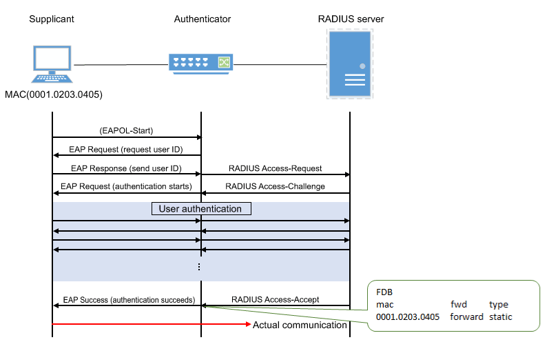
The supplicant is connected to the LAN, and transmits a communication start message (EAPOL-Start) message to start authentication.
When authentication succeeds, authentication success (Success) notification is sent to the supplicant, and the supplicant's MAC address is registered in the FDB, allowing the supplicant to access the network.
If authentication fails, an authentication failure (Failure) notification is sent to the supplicant, and network access is denied for the supplicant.
(Even without authentication, it is possible to allow access to a specific VLAN if a guest VLAN has been specified.)
3.2 MAC authentication
MAC authentication uses the MAC address of a device to authenticate an individual device.
Since the supplicant does not need special functionality to be authenticated, authentication is possible even for devices that do not support IEEE 802.1X.
The basic procedure for MAC authentication is shown in the following diagram.
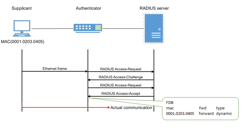
When this L2 switch receives any Ethernet frame from the supplicant, it queries the RADIUS server with the supplicant's MAC address as the user name and password.
EAP-MD5 is used as the authentication mode between this L2 switch and the RADIUS server.
When authentication succeeds, the supplicant's MAC address is registered in the FDB, allowing the supplicant to access the network.
If authentication fails, the supplicant is denied network access.
(Even without authentication, it is possible to allow access to a specific VLAN if a guest VLAN has been specified.)
The supplicant's MAC address must be registered as the user name and password in the RADIUS server, in one of the following formats.
- XX-XX-XX-XX-XX-XX (hyphen delimited)
- XX:XX:XX:XX:XX:XX (colon delimited)
- XXXXXXXXXXXX (not delimited)
This L2 switch lets you use the auth-mac auth-user commands to change the format of the MAC address query that is made to the RADIUS server.
Specify the appropriate command according to the format of the MAC addresses that are registered in the RADIUS server.
3.3 Host mode
This L2 switch lets you select the host mode for the port authentication function.
Host mode indicates how an applicable supplicant's communication will be permitted on the authentication port.
This L2 switch lets you choose from the following host modes.
- Single host mode
This mode permits communication for only one supplicant for each LAN/SFP port.
Communication is permitted only for the first supplicant that successfully authenticates.
- Multi-host mode
This mode permits communication for multiple supplicants for each LAN/SFP port.
When a supplicant successfully authenticates and communication is permitted, another supplicant that is connected to the same LAN/SFP port and that successfully authenticates is also permitted to communicate on the same VLAN.
3.4 Authentication VLAN
This L2 switch supports an authentication VLAN for its port authentication functionality.
An authentication VLAN is a function that changes the authentication port's associated VLAN according to the VLAN attributes of authentication data received from the RADIUS server.
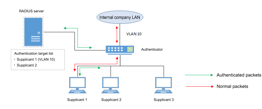
As shown in the illustration above, if a port's associated VLAN is 1, and the received authentication data has a VLAN attribute of 10, then following successful authentication, the authentication port's associated VLAN is 10, and communication on VLAN 10 is permitted.
For the RADIUS server, make settings so that the authentication information sent from the server includes the following attribute values.
- Tunnel-Type = VLAN (13)
- Tunnel-Medium-Type = IEEE-802 (6)
- Tunnel-Private-Group-ID = VLAN ID
If an authentication VLAN is used, operation in the various host modes will be as follows.
- Single host mode
The authentication port's associated VLAN is changed according to the VLAN attribute value of the supplicant that successfully authenticates.
- Multi-host mode
The authentication port's associated VLAN is changed according to the VLAN attribute value of the supplicant that successfully authenticates.
Other supplicants that are connected to the same port are also permitted to communicate on the same VLAN.
3.5 VLAN for unauthenticated or failed-authentication ports
This L2 switch's port authentication function allows you to specify a guest VLAN so that unauthenticated ports or ports that failed authentication will be assigned to a specific VLAN.
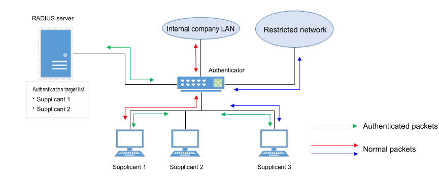
This is useful when you want to provide partial functionality on a limited network even to a supplicant that has not succeeded in authenticating, as shown in the illustration above.
4 Related Commands
Related commands are shown below.
For details on the commands, refer to the Command Reference.
List of related commands
| Operations | Operating commands |
|---|---|
| Set IEEE 802.1X authentication function for the entire system | aaa authentication dot1x |
| Set MAC authentication function for the entire system | aaa authentication auth-mac |
| Set IEEE 802.1X authentication function operating mode | dot1x port-control |
| Set unauthenticated port forwarding control for IEEE 802.1X authentication | dot1x control-direction |
| Set number of retransmitted EAPOL packets | dot1x max-auth-req |
| Set MAC authentication function | auth-mac enable |
| Set MAC address format setting for MAC authentication | auth-mac auth-user |
| Set host mode | auth host-mode |
| Set reauthentication | auth reauthentication |
| Set dynamic VLAN | auth dynamic-vlan-creation |
| Set guest VLAN | auth guest-vlan |
| Set restriction period following failed authentication | auth timeout quiet-period |
| Set reauthentication interval | auth timeout reauth-period |
| Set response wait time for the entire RADIUS server | auth timeout server-timeout |
| Set response wait time for the supplicant | auth timeout supp-timeout |
| Set RADIUS server host | radius-server host |
| Set response wait time for a single RADIUS server | radius-server timeout |
| Set number of times to retransmit request to RADIUS server | radius-server retransmit |
| Set shared password for RADIUS server | radius-server key |
| Set availability time restriction for RADIUS server | radius-server deadtime |
| Show port authentication status | show auth status |
| Show RADIUS server setting status | show radius-server |
5 Examples of Command Execution
5.1 Set IEEE 802.1X authentication
Make settings so that IEEE 802.1X authentication can be used.
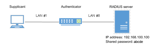
- We will use LAN port #1 as the authentication port to which the supplicant is connected.
- We will set the host mode to multi-host mode.
- We will use VLAN #10 as the guest LAN.
- We will use 192.168.100.100 as the RADIUS server that is connected.
- Define VLAN #10 as the guest VLAN.
L2SW(config)#vlan database
L2SW(config-vlan)#vlan 10               ... (VLAN #10 definition)
L2SW(config-vlan)#exit
- Enable the IEEE 802.1X authentication function for the entire system.
L2SW(config)#aaa authentication dot1x
- Set IEEE 802.1X authentication for LAN port #1.
L2SW(config)#interface ge1
L2SW(config-if)#dot1x port-control auto    ... (Set IEEE 802.1X authentication operating mode to auto)
L2SW(config-if)#auth host-mode multi-host  ... (Set host mode to multi-host mode)
L2SW(config-if)#auth guest-vlan 10         ... (Set guest VLAN as VLAN #10)
L2SW(config-if)#exit
- Set RADIUS server settings.
L2SW(config)#radius-server host 192.168.100.100 key abcde ... (Set host as 192.168.100.101, shared password as "abcde")
- Check RADIUS server settings.
L2SW#show radius-server
Server Host : 192.168.100.100
  Authentication Port : 1812
  Secret Key          : abcde
  Timeout             : 5 sec
  Retransmit Count    : 3
  Deadtime            : 0 min
- Check port authentication settings.
L2SW#show auth status
5.2 Set MAC authentication
Make settings so that MAC authentication can be used.
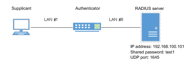
- We will use LAN port #1 as the authentication port to which the supplicant is connected.
- We will set the host mode to multi-host mode.
- We will use 192.168.100.101 as the RADIUS server that is connected.
- Enable the MAC authentication function for the entire system.
L2SW(config)#aaa authentication auth-mac
- Set MAC authentication for LAN port #1.
L2SW(config)#interface ge1
L2SW(config-if)#auth-mac enable                  ... (Enable MAC authentication)
L2SW(config-if)#auth host-mode multi-host        ... (Set host mode to multi-host mode)
L2SW(config-if)#exit
- Set RADIUS server settings.
L2SW(config)#radius-server host 192.168.100.101 auth-port 1645 key test1 (Set host as 192.168.100.101, UDP authentication port as 1645, and shared password as "test1") - Check RADIUS server settings.
L2SW#show radius-server
Server Host : 192.168.100.101
  Authentication Port : 1645
  Secret Key          : test1
  Timeout             : 5 sec
  Retransmit Count    : 3
  Deadtime            : 0 min
- Check port authentication settings.
L2SW#show auth status
6 Points of Caution
The port authentication function can be used from Rev.2.01.08 on.
Note that you cannot use this functionality on older versions.
7 Related Documentation
- SWP1 Series Technical Data (Basic Functions)
- L2 switching functions
FDB
1 Function Overview
The forwarding database (hereafter called "FDB") manages the destination MAC address, sending port and VLAN as a set. On this L2 switch, the FDB is used when determining the forwarding destination port for received frames.
By forwarding to a specified LAN/SFP port using the destination MAC address, useless traffic due to unicast frames can be suppressed.
This L2 switch provides the functions for FDB as shown in the table below.
- Enable/disable acquisition function
- Timeout adjustment for FDB entries acquired
- Timeout clear for FDB entries acquired
- Manual registration of FDB entries (static entries)
2 Definition of Terms Used
- FDB
Abbreviation of "Forwarding Database".
This database manages the destination MAC address, sending port and VLAN as a set.
- FDB entry
Data registered in the FDB.Structured using multiple elements.
3 Function Details
3.1 FDB entry
On this L2 switch, the contents listed in the table below are registered as a single entry in the FDB.
FDB entry
| Element managed | Description |
|---|---|
| VLAN ID | The VLAN ID to which this unit is associated.This is a value from 1–4096. |
| MAC address | The MAC address for the device. |
| Port number | The interface on which the device resides*. (*: LAN/SFP port or static/LACP logical interface) |
| Action | The method of processing the frame addressed to the device. There are two processing methods, "discard" and "forward". |
| Registration classification | The registration type for the entry. The types are shown below.
|
Up to 16,384 addresses can be registered on this L2 switch, including entries registered via automatic acquisition and manual learning.
The MAC addresses of all received frames can be acquired, and the source MAC address is acquired and registered in the FDB.
The registered MAC address information will be maintained until the ageing timeout.
MAC address acquisition is done per VLAN, and the MAC address and VLAN are managed in the FBD as a pair.
For different VLANs, identical MAC addresses are also acquired.
3.2 Automatic MAC address acquisition
Automatic MAC address acquisition refers to the active creation of FBD entries based on the information for the source MAC address of the received frame, and the reception port.
Entries registered through automatic acquisition are called "dynamic entries".
A timer (ageing time) is used to monitor individual entries.
Entries for MAC addresses that have not received frames within a certain amount of time will be deleted from the FDB.
This prevents invalid device entries from being left over in the FDB due to power shutoff, being moved and so on.
If a frame is received within the specified amount of time, the monitoring timer will be reset.
The control specifications for automatic acquisition are shown below.
- Automatic MAC address acquisition can be enabled or disabled using the "mac-address-table acquire" command.
The setting is enabled by default.
- If automatic acquisition is changed from enabled to disabled, all dynamic entries that have been learned will be deleted.
The acquisition function "disable" setting is useful when you want to flood all ports with all received frames.
- The ageing time for dynamic entries can be adjusted by specifying a value from 10–634 seconds, using the "mac-address-table ageing-time" command.
This value is set to 300 seconds by default.
- Clear the dynamic entries that have been acquired by using the "clear mac-address-table dynamic" command.
The entire contents of the FDB can be cleared at once; or a VLAN number can be specified and all MAC addresses acquired by that VLAN can be cleared from the FDB.
Specifying the port number will clear all MAC addresses from the FDB that were acquired from that port. - Use the "show mac-address-table" command to check the automatic acquisition status.
3.3 Setting MAC addresses manually
In addition to automatic acquisition using received frames, MAC addresses can be set on this L2 switch with user commands.
Entries that have been registered by using commands are called "static entries".
The specifications for manual settings are shown below.
- Use the "mac-address-table static" command to register static entries.
- Use the "no mac-address-table static" command to delete static entries.
- Either "forward" or "discard" can be specified for the destination MAC address of a received frame.
- When forwarding is specified, either the LAN/SFP port forwarding destination or the static/LACP logical interface can be specified.
- When discarding is specified, frames received by the MAC address will not be forwarded to any port, and will be discarded.
- When registering static entries, dynamic acquisition will not be performed on the corresponding MAC addresses.
Entries that have already been acquired will be deleted from the FDB, and will be registered as static entries.
4 Related Commands
The related commands are shown below.
For details on the commands, refer to the Command Reference.
List of related commands
| Operations | Operating commands |
|---|---|
| Enable/disable MAC address acquisition function | mac-address-table acquire |
| Set dynamic entry ageing time | mac-address-table ageing-time |
| Clear dynamic entry | clear mac-address-table dynamic |
| Register static entry | mac-address-table static |
| Delete static entry | no mac-address-table static |
| Delete IGMP/MDL snooping multicast address | clear mac-address-table multicast |
| Refer to MAC address table | show mac-address-table |
5 Examples of Command Execution
5.1 Referring to the FDB
L2SW# show mac-address-table
VLAN  port   mac             fwd      type     timeout
   1  ge2    00a0.de11.2233  forward  static        0
   1  ge1    1803.731e.8c2b  forward  dynamic     300
   1  ge1    782b.cbcb.218d  forward  dynamic     300
5.2 Deleting a dynamic entry
Deleting an FDB entry registered in the FBD (MAC address 00:a0:de:11:22:33)
L2SW# clear mac-address-table dynamic address 00a0.de11.2233
5.3 Changing the dynamic entry ageing time
This example shows how to change the dynamic entry ageing time to 600 seconds.
L2SW(config)# mac-address-table ageing-time 600
5.4 Registering a static entry
This example shows how to forward the frames sent to a device associated with VLAN #10 (MAC address 00:a0:de:11:22:33) to LAN port 2 (ge2).
L2SW(config)# mac-address-table static 00a0.de11.2233 forward ge2 vlan 10
This example shows how to discard the frames sent to a device associated with VLAN #10 (MAC address 00:a0:de:11:22:33).
Specifying the interface name ("ge2" in the example) will have no effect on operations.Since this cannot be omitted, specify the LAN/SFP port.
L2SW(config)# mac-address-table static 00a0.de11.2233 discard ge2 vlan 10
5.5 Deleting a static entry
This example shows how to delete the forwarding settings sent to a device associated with VLAN #10 (MAC address 00:a0:de:11:22:33).
L2SW(config)# no mac-address-table static 00a0.de11.2233 forward ge2 vlan 10
6 Points of Caution
None
7 Related Documentation
None
VLAN
1 Function Overview
VLAN (Virtual LAN) is a technology for dividing a single physical network into multiple logical networks.
When VLAN is used with an L2 switch, the switch can be divided up into multiple broadcast domains like a router (L3 switch).
The VLANs that are supported by this L2 switch are shown below.
Supported VLAN types
| VLAN types | Summary |
|---|---|
| Port-based VLAN | Groups that can communicate are configured for each LAN/SFP port. |
| Tagged VLAN | Groups that can communicate are identified, based on the fixed-length tag information appended to the Ethernet frame. Multiple and different VLANs can be made to communicate by means of one LAN/SFP port. |
| Private VLAN | Groups that can communicate within the same VLAN are divided up. This includes the following three VLAN types.
|
2 Definition of Terms Used
- Broadcast domain
This is a range in which broadcast frames can be delivered in a network, such as an Ethernet.
Devices that are connected by relaying a data link layer (MAC layer), such as switching hubs, can belong to the same broadcast domain.
A broadcast domain generally refers to the network in an Ethernet.
3 Function Details
3.1 VLAN ID: definition
On this L2 switch, a maximum of 255 VLANs can be defined, with VLAN IDs ranging from 2–4094. (ID #1 is used as the default VLAN ID.)
VLAN IDs are defined using the "vlan" command, after the "vlan database" command is used to enter VLAN mode.
For details, refer to the Command Reference.
3.2 VLAN settings for the LAN/SFP ports
The following settings must be configured after defining the VLANs to use, in order to make use of VLAN on this L2 switch.
- LAN/SFP port mode settings
- VLAN associations for LAN/SFP ports
The VLAN control specifications for LAN/SFP ports on this L2 switch are shown below.
For details on the command specifications, refer to the Command Reference.
- The LAN/SFP ports on this L2 switch are set to one of the following modes.
- Access port
This is a port that handles untagged frames. It can be associated with one VLAN. - Trunk port
This is a port that handles both tagged and untagged frames.
It can be associated with multiple VLANs, and is mainly used to connect switches to one another.
This L2 switch only supports IEEE 802.1Q. (Cisco ISL is not supported.)
- Access port
- Use the "switchport mode" command to set the LAN/SFP port mode.
When setting the trunk port, use the input filter ("ingress-filter") to control whether frames not belonging to the specified VLAN ID will be handled.
- Input filter enabled: only frames set to the specified VLAN ID will be handled.
- Input filter disabled: all VLAN IDs will be handled.
- Use the "show interface switchport" command to check the LAN/SFP port setting mode.
- Use the "switchport access vlan" command to set which VLANs belong to the access port.
- Use the "switchport trunk allowed vlan" command to set which VLANs belong to the trunk port.
As the trunk port can be associated with multiple VLANs, use the "all", "none", "except", "add" and "remove" settings as shown below.
- add
Adds the specified VLAN ID.
VLAN IDs that can be added are limited by the IDs that are defined by the VLAN mode.
- remove
Deletes the specified VLAN ID.
- all
Adds all VLAN IDs specified by the VLAN mode.
The VLAN IDs added by the VLAN mode can also be added after this command is executed.
- none
The trunk port will not be associated with any VLAN.
- except
Adds all other VLAN IDs except for the ones specified.
The VLAN IDs added by the VLAN mode can also be added after this command is executed.
- add
- A VLAN that uses untagged frames (native VLAN) can be specified for the trunk port.
- Use the "show vlan" command to check which VLANs belong to a LAN/SFP port.
3.3 VLAN access restriction
This L2 switch provides an VLAN access map function, to control access to the VLAN.
The VLAN access map can be associated with a standard/extended IP access control list and a MAC address control list as VLAN ID filtering parameters.
The VLAN access map is operated using the commands shown below.
- Create VLAN access map: "vlan access-map" command
- Set VLAN access map parameters: "match access-list" command
- Assign VLAN access map: "vlan filter" command
- Show VLAN access map: "show vlan access-map" command
3.4 Default VLAN
The default VLAN is VLAN #1 (vlan0.1), which exists in this switch by default.
As the default VLAN is a special VLAN, it always exists and cannot be deleted.
The following operations can be used to automatically delete the relevant port from the default VLAN.
- Setting the VLAN for an access port
- Setting any VLAN other than the default as the native VLAN for the trunk port
- Setting the native VLAN for the trunk port to "none"
3.5 Native VLAN
A native VLAN is a VLAN that associates untagged frames received by the LAN/SFP port that was set as a trunk port.
Defining an LAN/SFP port as a trunk port will set the default VLAN (VLAN #1) as the native VLAN.
Use the "switchport trunk native vlan" command when specifying a certain VLAN as the native VLAN.
The native LAN can be set to none, when setting the relevant LAN/SFP port to not handle untagged frames. (Specify "none" in the "switchport trunk native vlan" command.)
Use caution when setting untagged frames to not be handled, as the following functions will be unavailable.
- L2MS control (LAN map control, HTTP proxy control)
- SWX2200 loop detection
- WLX302 AP linking
3.6 Private VLAN
The SXWS2300 can configure a private VLAN for further dividing up groups that can communicate within the same subnet.
The operating specifications are shown below.
- A private VLAN contains the following three VLAN types.
- Primary VLAN
This is the parent VLAN of the secondary VLAN.
Only one primary VLAN can be set per private VLAN.
- Isolated VLAN
This is a kind of secondary VLAN, which only sends traffic to a primary VLAN.
Only one isolated VLAN can be set per private VLAN.
- Community VLAN
This is a kind of secondary VLAN, which only sends traffic to VLANs in the same community and to a primary VLAN.
Multiple community VLANs can be set for each private VLAN.
- Primary VLAN
- A primary VLAN may contain multiple promiscuous ports.
Only access ports, trunk ports, and static/LACP logical interfaces can be used as promiscuous ports.
- Only access ports can be used as host ports for a secondary VLAN (isolated VLAN, community VLAN).
- A secondary VLAN (isolated VLAN, community VLAN) can be associated with one primary VLAN.
Use the "switchport private-vlan mapping" to create the association.
- An isolated VLAN can be associated with multiple promiscuous ports contained within a private VLAN.
- A community VLAN can be associated with multiple promiscuous ports contained within a private VLAN.
4 Related Commands
The related commands are shown below.
For details on the commands, refer to the Command Reference.
List of related commands
| Operations | Operating commands |
|---|---|
| Enter VLAN mode | vlan database |
| Define VLAN interface, or change a predefined VLAN | vlan |
| Define a private VLAN | private-vlan |
| Set the secondary VLAN for a private VLAN | private-vlan association |
| Create VLAN access map | vlan access-map |
| Set VLAN access map parameters | match |
| Assign VLAN access map to VLAN | vlan filter |
| Set access port (untagged port) | switchport mode access |
| Set associated VLAN of an access port (untagged port) | switchport access vlan |
| Set trunk port (tagged port) | switchport mode trunk |
| Set associated VLAN for trunk port (tagged port) | switchport trunk allowed vlan |
| Set native VLAN for trunk port (tagged port) | switchport trunk native vlan |
| Set ports for private VLAN (promiscuous port, host port) | switchport mode private-vlan |
| Configure VLAN for private VLAN port and host port | switchport private-vlan host-association |
| Configure VLAN for private VLAN port and promiscuous port | switchport private-vlan mapping |
| Show VLAN information | show vlan |
| Show private VLAN information | show vlan private-vlan |
| Show VLAN access map | show vlan access-map |
| Show VLAN access map filter | show vlan filter |
5 Examples of Command Execution
5.1 Port-based VLAN settings
In this example, the port-based VLAN is configured in order to communicate between hosts A–B and hosts C–D.
Port VLAN setting example
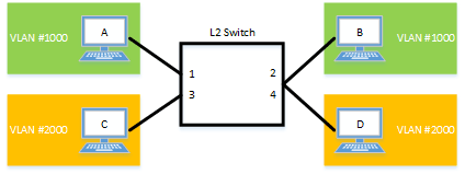
The LAN port settings for this L2 switch are as follows.
- Set LAN ports #1/#2 as access ports, and associate them with VLAN #1000.
- Set LAN ports #3/#4 as access ports, and associate them with VLAN #2000.
- Switch to VLAN mode using the "vlan database" command, and define two VLANs using the "vlan" command.
L2SW(config)# vlan database … (Move to VLAN mode.)
L2SW(config-vlan)# vlan 1000 … (Set VLAN #1000)
L2SW(config-vlan)# vlan 2000 … (Set VLAN #2000)
L2SW(config-if)# exit
- Set LAN ports #1–2 as access ports, and associate them with VLAN #1000.
L2SW(config)# interface ge1 … (Move to interface mode.)
L2SW(config-if)# switchport mode access … (Set as an access port.)
L2SW(config-if)# switchport access vlan 1000 … (Set VLAN #1000 as the VLAN.
L2SW(config-if)# exit
(Apply same operation to ge2.)
- Set LAN ports #3–4 as access ports, and associate them with VLAN #2000.
L2SW(config)# interface ge3
L2SW(config-if)# switchport mode access
L2SW(config-if)# switchport access vlan 2000
L2SW(config-if)# exit
(Apply same operation to ge4.)
- Confirm the VLAN settings.
L2SW# show vlan brief
(u)-Untagged, (t)-Tagged
VLAN ID  Name            State   Member ports
======= ================ ======= ===============================
1       default          ACTIVE  ge5(u) ge6(u) ge7(u) ge8(u)
1000    VLAN1000         ACTIVE  ge1(u) ge2(u)
2000    VLAN2000         ACTIVE  ge3(u) ge4(u)
5.2 Tagged VLAN settings
In this example, a tagged VLAN is configured between #A and #B of this L2 switch, in order to communicate between hosts A–B and hosts C–D.
Tagged VLAN setting example

The LAN port settings for #A/#B of this L2 switch are as follows.
- Set LAN port #1 as an access port, and associate it with VLAN #1000
- Set LAN port #2 as an access port, and associate it with VLAN #2000
- Set LAN port #3 as a trunk port, and associate it with LAN #1000 and VLAN #2000
- [Switch #A/#B] Define VLAN.
L2SW(config)# vlan database … (Move to vlan mode.)
L2SW(config-vlan)# vlan 1000 … (Set vlan0.1000)
L2SW(config-vlan)# vlan 2000 … (Set vlan0.2000)
- [Switch #A/#B] Set LAN port #1 as the access port, and associate it with VLAN #1000.
L2SW(config)# interface ge1 … (Move to interface mode.)
L2SW(config-if)# switchport mode access … (Set as an access port.)
L2SW(config-if)# switchport access vlan 1000 … (Set VLAN #1000 as the VLAN.)
L2SW(config-if)# exit
- [Switch #A/#B] Set LAN port #2 as the access port, and associate it with VLAN #2000.
L2SW(config)# interface ge2 … (Move to interface mode.)
L2SW(config-if)# switchport mode access … (Set as an access port.)
L2SW(config-if)# switchport access vlan 2000 … (Set VLAN #2000 as the VLAN.)
L2SW(config-if)# exit
- [Switch #B] Set LAN port #3 as a trunk port, and associate it with VLAN #1000/#2000.
L2SW(config)# interface ge3 … (Move to interface mode.)
L2SW(config-if)# switchport mode trunk … (Set as a trunk port.
L2SW(config-if)# switchport trunk allowed vlan add 1000 … (Aassociate it to vlan 0.1000.)
L2SW(config-if)# switchport trunk allowed vlan add 2000 … (Aassociate it to vlan 0.2000.)
L2SW(config-if)# exit
- Confirm the VLAN settings.
L2SW# show vlan brief
(u)-Untagged, (t)-Tagged

VLAN ID  Name                            State   Member ports
======= ================================ ======= ======================
1       default                          ACTIVE  ge3(u)
1000    VLAN1000                         ACTIVE  ge1(u) ge3(t)
2000    VLAN2000                         ACTIVE  ge2(u) ge3(t)
5.3 Private VLAN settings
This example sets the private VLAN for this L2 switch, to achieve the following.
Hosts connected to ports 1–7 will connect to the Internet and other external lines, through the line to which port 8 is connected
Communications between hosts connected to ports 1–4 are blocked (isolated VLAN: VLAN #21)
Communications between hosts connected to ports 5–7 are permitted (community VLAN: VLAN #22)
Communications between hosts connected to ports 1–4 and ports 5–7 are blocked
Private VLAN setting example
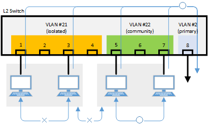
- Define the VLAN ID to be used for the private VLAN.
L2SW(config)# vlan database … (Move to VLAN mode.)
L2SW(config-vlan)# vlan 2  … (Set VLAN.)
L2SW(config-vlan)# vlan 21
L2SW(config-vlan)# vlan 22
L2SW(config-vlan)# private-vlan 2 primary … (Set the primary VLAN.)
L2SW(config-vlan)# private-vlan 21 isolated … (Set the isolated VLAN.)
L2SW(config-vlan)# private-vlan 22 community … (Set the community VLAN.)
L2SW(config-vlan)# private-vlan 2 association add 21 … (Associate Primary VLAN)
L2SW(config-vlan)# private-vlan 2 association add 22
L2SW(config-vlan)# exit
- Configure the isolated VLAN (VLAN #21) for LAN ports 1–4.
L2SW(config)# interface ge1 … (Move to interface mode.)
L2SW(config-if)# switchport mode access … (Set as an access port.)
L2SW(config-if)# switchport access vlan 21 .. (Set VLAN #21 as the VLAN.)
L2SW(config-if)# switchport mode private-vlan host … (Set as a host port of the private VLAN.)
L2SW(config-if)# switchport private-vlan host-association 2 add 21
L2SW(config-if)# exit

(Also specify the above setting to ge2-ge4.)
- Configure the community VLAN (VLAN #22) for LAN ports 5–7.
L2SW(config)# interface ge5 … (Move to interface mode.)
L2SW(config-if)# switchport mode access … (Set as an access port.)
L2SW(config-if)# switchport access vlan 22 … (Set VLAN #22 as the VLAN.)
L2SW(config-if)# switchport mode private-vlan host … (Set as a host port of the private VLAN.)
L2SW(config-if)# switchport private-vlan host-association 2 add 22
L2SW(config-if)# exit

(Also specify the above setting to ge6 and ge7.)
- Configure the primary VLAN (VLAN #2) for LAN port 8.(Promiscuous port)
L2SW(config)# interface ge8 … (Move to interface mode.)
L2SW(config-if)# switchport mode access … (Set as an access port.)
L2SW(config-if)# switchport access vlan 2 … (Set VLAN #2 as the VLAN.)
L2SW(config-if)# switchport mode private-vlan promiscuous … (Set as a promiscuous port of the private VLAN.)
L2SW(config-if)# switchport private-vlan mapping 2 add 21
L2SW(config-if)# switchport private-vlan mapping 2 add 22
L2SW(config-if)# exit
- Confirm the VLAN settings.
L2SW# show vlan brief
(u)-Untagged, (t)-Tagged

VLAN ID  Name                            State   Member ports
======= ================================ ======= ======================
1       default                          ACTIVE
2       VLAN0002                         ACTIVE  ge8(u)
21      VLAN0021                         ACTIVE  ge1(u) ge2(u) ge3(u)
                                                 ge4(u)
22      VLAN0022                         ACTIVE  ge5(u) ge6(u) ge7(u)

L2SW#show vlan private-vlan
 PRIMARY        SECONDARY          TYPE          INTERFACES
 -------        ---------       ----------      ----------
       2              21          isolated       ge1 ge2 ge3 ge4
       2              22         community       ge5 ge6 ge7
6 Points of Caution
- Ports that belong to a private VLAN cannot be combined as a link aggregation logical interface (host ports only).
- When specifying a VLAN ID with a combination of “-” and “,” characters, the commands below will fail when reverting to a previous version (before Rev.2.01.04).
As a result, normal communications may not be possible.(Example of settings: switchport trunk allowed vlan add 101,103-105)
- switchport trunk allowed vlan add VLAN-IDS
- switchport private-vlan mapping PRI-VLAN-ID add 2ND-VLAN-IDS
- private-vlan PRI-VLAN-ID association add 2ND-VLAN-IDS
7 Related Documentation
None
Spanning tree
1 Function Overview
The spanning tree is a function that maintains redundancies in the network routes while preventing loops.
Normally, the L2 switch floods the adjacent switch with the broadcast packets.
If the network is constructed as a loop, the switches will flood each other, causing the loop to occur.
This results in a major degradation of bandwidth and CPU resources in the switches.
The spanning tree determines the roles of each port and establishes a network construction where the broadcast packets do not keep traveling around, for networks that contain physical loops as well.
When there are problems linking, the problem is detected and the tree is reconstructed in order to restore the system.
This L2 switch supports STP, RSTP, and MSTP.
Spanning tree function overview
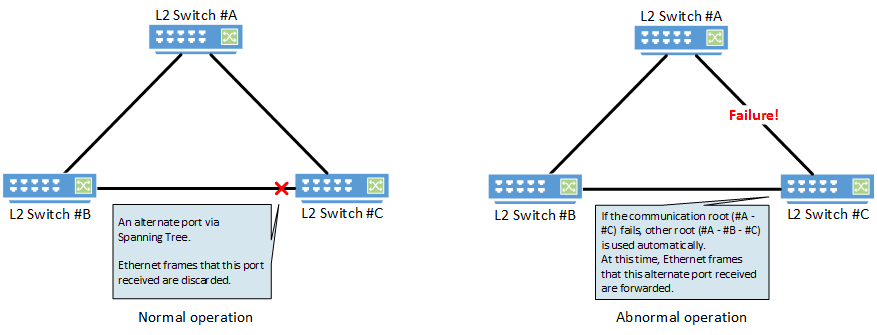
2 Definition of Terms Used
- STP: Spanning Tree Protocol (802.1d)
The spanning tree protocol (STP) exchanges BPDU (bridge protocol data unit) messages, in order to avoid loops.
This L2 switch supports IEEE802.1d and RFC4188.
- RSTP: Rapid Spanning Tree Protocol (802.1w)
The rapid spanning tree protocol (RSTP) is an extension of STP. It can recover the spanning tree more quickly than STP, when the network architecture has changed or when there is a problem linking.
This L2 switch supports IEEE802.1w and RFC4318.
- MSTP: Multiple Spanning Tree Protocol (802.1s)
Multiple spanning tree protocol (MSTP) is a further extension of STP and RSTP. It groups the VLAN into instances, and constructs a spanning tree for each group.
This can be used to distribute load within the network routes.
This L2 switch supports IEEE802.1s.
3 Function Details
This L2 switch is compatible with the following functions, in order to flexibly handle the construction of routes based on MSTP.
- Set priority
- Set bridge priority
- Set port priority
- Set path cost
- Set timeout
- Set forward delay time
- Set maximum ageing time
- Specify edge port (Port Fast settings)
- BPDU guard
- BPDU filtering
- Route guard
4 Related Commands
The related commands are shown below.
For details on the commands, refer to the Command Reference.
List of related commands
| Operations | Operating commands |
|---|---|
| Set spanning tree for the system | spanning-tree shutdown |
| Set forward delay time | spanning-tree forward-time |
| Set maximum ageing time | spanning-tree max-age |
| Set bridge priority | spanning-tree priority |
| Set spanning tree for an interface | spanning-tree |
| Set spanning tree link type | spanning-tree link-type |
| Set interface BPDU filtering | spanning-tree bpdu-filter |
| Set interface BPDU guard | spanning-tree bpdu-guard |
| Set interface path cost | spanning-tree path-cost |
| Set interface priority | spanning-tree priority |
| Set edge port for interface | spanning-tree edgeport |
| Show spanning tree status | show spanning-tree |
| Show spanning tree BPDU statistics | show spanning-tree statistics |
| Clear protocol compatibility mode | clear spanning-tree detected protocols |
| Move to MST mode | spanning-tree mst configuration |
| Generate MST instance | instance |
| Set VLAN for MST instance | instance vlan |
| Set priority of MST instance | instance priority |
| Set MST region name | region |
| Set revision number of MST region | revision |
| Set MST instance for interface | spanning-tree instance |
| Set interface priority for MST instance | spanning-tree instance priority |
| Set interface path cost for MST instance | spanning-tree instance path-cost |
| Show MST region information | show spanning-tree mst config |
| Show MSTP information | show spanning-tree mst |
| Show MST instance information | show spanning-tree mst instance |
5 Examples of Command Execution
5.1 MSTP setting example
This L2 switch can be used to realize the architecture shown in the diagram below.
MSTP architecture diagram
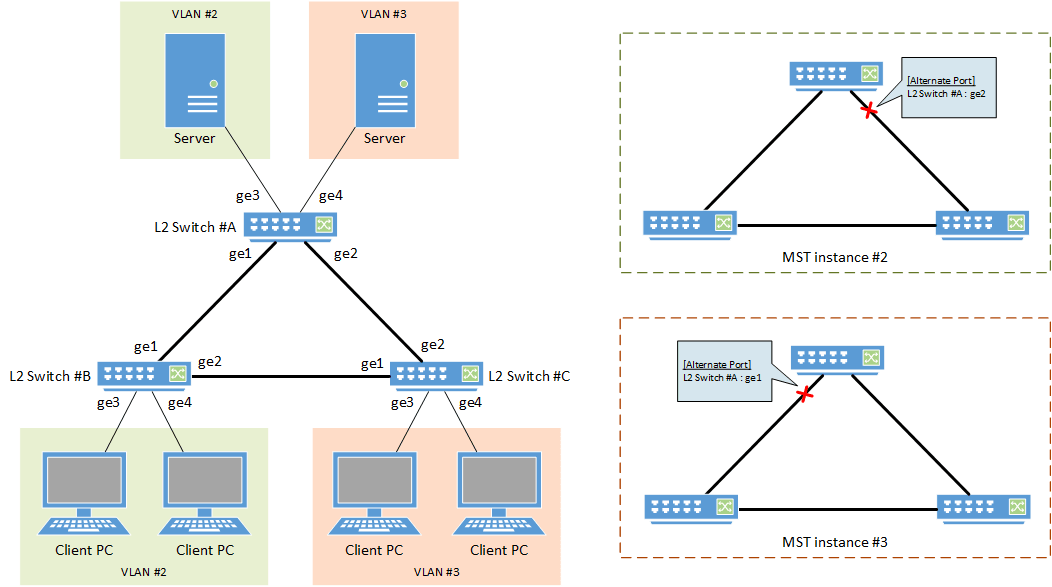
- In this example, MST instances are used to construct the spanning tree.
- A different route is set for each MST instance (VLAN), in order to distribute network load.
- The LAN port that is connected to the PC is set as the edge port.
- [Switch #A] Define VLAN #2 and VLAN #3.
L2SW(config)# vlan database
L2SW(config-vlan)# vlan 2                              ... (Set VLAN #2.)
L2SW(config-vlan)# vlan 3                              ... (Set VLAN #3.)
L2SW(config-vlan)# exit
- [Switch #A] Set the CIST priority.
L2SW(config)# spanning-tree priority 8192 ... (Set the priority for CIST to 8192.)
- [Switch #A] Set the MST.
L2SW(config)# spanning-tree mst configuration
L2SW(config-mst)# region Sample                        ... (Set the MST region name to "Sample".)
L2SW(config-mst)# revision 1                           ... (Set the revision number as 1 for the MST region.)
L2SW(config-mst)# instance 2 vlan 2                    ... (Associate VLAN #2 with MST instance #2.)
L2SW(config-mst)# instance 3 vlan 3                    ... (Associate VLAN #3 with MST instance #3.)
L2SW(config-mst)# exit
- [Switch #A] Set LAN ports #1–#2 as trunk ports, and associate them with VLAN #2–#3.
Also, set the MST instances #2–#3.L2SW(config)# interface ge1 L2SW(config-if)# switchport mode trunk ... (Set as a trunk port.) L2SW(config-if)# switchport trunk allowed vlan add 2,3 ... (Aassociate it to VLAN #2,#3.) L2SW(config-if)# spanning-tree instance 2 ... (Set MST instance #2.) L2SW(config-if)# spanning-tree instance 3 ... (Set MST instance #3.) L2SW(config-if)# exit (Set VLAN #2 as the VLAN.)
- [Switch #A] Set LAN port #3 as the access port, and associate it with VLAN #2.
Also, set the MST instance #2, and make it an edge port.L2SW(config)# interface ge3 L2SW(config-if)# switchport mode access ... (Set as an access port.) L2SW(config-if)# switchport access vlan 2 ... (Set VLAN #2 as the VLAN.) L2SW(config-if)# spanning-tree instance 2 ... (Set MST instance #2.) L2SW(config-if)# spanning-tree edgeport ... (Sets as the edge port.) L2SW(config-if)# exit
- [Switch #A] Set LAN port #4 as the access port, and associate it with VLAN #3.
Also, set the MST instance #3, and make it an edge port.
L2SW(config)# interface ge4 L2SW(config-if)# switchport mode access ... (Set as an access port.) L2SW(config-if)# switchport access vlan 3 ... (Set VLAN #3 as the VLAN.) L2SW(config-if)# spanning-tree instance 3 ... (Set MST instance #3.) L2SW(config-if)# spanning-tree edgeport ... (Sets as the edge port.) L2SW(config-if)# exit
- [Switch #B] Define VLAN #2 and VLAN #3.
L2SW(config)# vlan database L2SW(config-vlan)# vlan 2 ... (Set VLAN #2) L2SW(config-vlan)# vlan 3 ... (Set VLAN #3) L2SW(config-vlan)# exit
- [Switch #B] Set the CIST priority.
L2SW(config)# spanning-tree priority 16384 ... (Set the priority for CIST to 16384.)
- [Switch #B] Set the MST.
L2SW(config)# spanning-tree mst configuration L2SW(config-mst)# region Sample ... (Set the MST region name to "Sample".) L2SW(config-mst)# revision 1 ... (Set the revision number as 1 for the MST region.) L2SW(config-mst)# instance 2 vlan 2 ... (Associate VLAN #2 with MST instance #2.) L2SW(config-mst)# instance 2 priority 8192 ... (Set MST instance #2 to a priority of 8192.) L2SW(config-mst)# instance 3 vlan 3 ... (Associate VLAN #3 with MST instance #3.) L2SW(config-mst)# instance 3 priority 16384 ... (Set MST instance #3 to a priority of 16384.) L2SW(config-mst)# exit
- [Switch #B] Set LAN ports #1–#2 as trunk ports, and associate them with VLAN #2–#3.
Also, set the MST instances #2–#3.
L2SW(config)# interface ge1 L2SW(config-if)# switchport mode trunk ... (Set as a trunk port.) L2SW(config-if)# switchport trunk allowed vlan add 2,3 ... (Aassociate it to VLAN #2,#3.) L2SW(config-if)# spanning-tree instance 2 ... (Set MST instance #2.) L2SW(config-if)# spanning-tree instance 3 ... (Set MST instance #3.) L2SW(config-if)# exit (Also specify the above setting to LAN port #2.)
- [Switch #B] Set LAN port #3 as the access port, and associate it with VLAN #2.
Also, set the MST instance #2, and make it an edge port.
L2SW(config)# interface ge3 L2SW(config-if)# switchport mode access ... (Set as an access port.) L2SW(config-if)# switchport access vlan 2 ... (Set VLAN #2 as the VLAN.) L2SW(config-if)# spanning-tree instance 2 ... (Set MST instance #2.) L2SW(config-if)# spanning-tree edgeport ... (Sets as the edge port.) L2SW(config-if)# exit (Also specify the above setting to LAN port #4.)
- [Switch #C] Define VLAN #2 and VLAN #3.
L2SW(config)# vlan database
L2SW(config-vlan)# vlan 2                              ... (Set VLAN #2)
L2SW(config-vlan)# vlan 3                              ... (Set VLAN #3)
L2SW(config-vlan)# exit
- [Switch #C] Set the MST.
L2SW(config)# spanning-tree mst configuration L2SW(config-mst)# region Sample ... (Set the MST region name to "Sample".) L2SW(config-mst)# revision 1 ... (Set the revision number as 1 for the MST region.) L2SW(config-mst)# instance 2 vlan 2 ... (Associate VLAN #2 with MST instance #2.) L2SW(config-mst)# instance 2 priority 16384 ... (Set MST instance #2 to a priority of 16384.) L2SW(config-mst)# instance 3 vlan 3 ... (Associate VLAN #3 with MST instance #3.) L2SW(config-mst)# instance 3 priority 8192 ... (Set MST instance #3 to a priority of 8192.) L2SW(config-mst)# exit
- [Switch #C] Set LAN ports #1–#2 as trunk ports, and associate them with VLAN #2–#3.
Also, set the MST instances #2–#3.
L2SW(config)# interface ge1
L2SW(config-if)# switchport mode trunk                 ... (Set as a trunk port.)
L2SW(config-if)# switchport trunk allowed vlan add 2,3 ... (Aassociate it to VLAN #2,#3.)
L2SW(config-if)# spanning-tree instance 2              ... (Set MST instance #2.)
L2SW(config-if)# spanning-tree instance 3              ... (Set MST instance #3.)
L2SW(config-if)# exit
(Also specify the above setting to LAN port #2.)
- [Switch #C] Set LAN port #3 as the access port, and associate it with VLAN #3.
Also, set the MST instance #3, and make it an edge port.
L2SW(config)# interface ge3
L2SW(config-if)# switchport mode access                ... (Set as an access port.)
L2SW(config-if)# switchport access vlan 3              ... (Set VLAN #3 as the VLAN.)
L2SW(config-if)# spanning-tree instance 3              ... (Set MST instance #3.)
L2SW(config-if)# spanning-tree edgeport                ... (Sets as the edge port.)
L2SW(config-if)# exit
(Also specify the above setting to LAN port #4.)
- Connect the LAN cable.
- [Switch #A] Check the CIST architecture.
L2SW>show spanning-tree | include Root Id
% Default: CIST Root Id 200100a0deaeb920      ... (The higher priority switch #A becomes the root bridge of CIST.)
% Default: CIST Reg Root Id 200100a0deaeb920

L2SW>show spanning-tree | include Role
%   ge1: Port Number 1 - Ifindex 1 - Port Id 8001 - Role Designated - State Forwarding
%   ge2: Port Number 2 - Ifindex 2 - Port Id 8002 - Role Designated - State Forwarding
%   ge3: Port Number 3 - Ifindex 3 - Port Id 8003 - Role Designated - State Forwarding
%   ge4: Port Number 4 - Ifindex 4 - Port Id 8004 - Role Designated - State Forwarding
%   ge5: Port Number 5 - Ifindex 5 - Port Id 8005 - Role Disabled - State Discarding
%   ge6: Port Number 6 - Ifindex 6 - Port Id 8006 - Role Disabled - State Discarding
%   ge7: Port Number 7 - Ifindex 7 - Port Id 8007 - Role Disabled - State Discarding
%   ge8: Port Number 8 - Ifindex 8 - Port Id 8008 - Role Disabled - State Discarding
%   ge9: Port Number 9 - Ifindex 9 - Port Id 8009 - Role Disabled - State Discarding
- [Switch #B] Check the CIST architecture.
L2SW>show spanning-tree | include Root Id
% Default: CIST Root Id 200100a0deaeb920      ... (The higher priority switch #A becomes the root bridge of CIST.)
% Default: CIST Reg Root Id 200100a0deaeb920

L2SW>show spanning-tree | include Role
%   ge1: Port Number 1 - Ifindex 1 - Port Id 8001 - Role Rootport - State Forwarding
%   ge2: Port Number 2 - Ifindex 2 - Port Id 8002 - Role Designated - State Forwarding
%   ge3: Port Number 3 - Ifindex 3 - Port Id 8003 - Role Designated - State Forwarding
%   ge4: Port Number 4 - Ifindex 4 - Port Id 8004 - Role Designated - State Forwarding
%   ge5: Port Number 5 - Ifindex 5 - Port Id 8005 - Role Disabled - State Discarding
%   ge6: Port Number 6 - Ifindex 6 - Port Id 8006 - Role Disabled - State Discarding
%   ge7: Port Number 7 - Ifindex 7 - Port Id 8007 - Role Disabled - State Discarding
%   ge8: Port Number 8 - Ifindex 8 - Port Id 8008 - Role Disabled - State Discarding
%   ge9: Port Number 9 - Ifindex 9 - Port Id 8009 - Role Disabled - State Discarding
- [Switch #C] Check the CIST architecture.
L2SW>show spanning-tree | include Root Id
% Default: CIST Root Id 200100a0deaeb920      ... (The higher priority switch #A becomes the root bridge of CIST.)
% Default: CIST Reg Root Id 200100a0deaeb920

L2SW>show spanning-tree | include Role
%   ge1: Port Number 1 - Ifindex 1 - Port Id 8001 - Role Alternate - State Discarding ... (The port of LAN #1 in the lower priority switch #C becomes the substitute port of CIST.)
%   ge2: Port Number 2 - Ifindex 2 - Port Id 8002 - Role Rootport - State Forwarding
%   ge3: Port Number 3 - Ifindex 3 - Port Id 8003 - Role Designated - State Forwarding
%   ge4: Port Number 4 - Ifindex 4 - Port Id 8004 - Role Designated - State Forwarding
%   ge5: Port Number 5 - Ifindex 5 - Port Id 8005 - Role Disabled - State Discarding
%   ge6: Port Number 6 - Ifindex 6 - Port Id 8006 - Role Disabled - State Discarding
%   ge7: Port Number 7 - Ifindex 7 - Port Id 8007 - Role Disabled - State Discarding
%   ge8: Port Number 8 - Ifindex 8 - Port Id 8008 - Role Disabled - State Discarding
%   ge9: Port Number 9 - Ifindex 9 - Port Id 8009 - Role Disabled - State Discarding
- [Switch #A] Check the architecture of MST instance #2.
L2SW>show spanning-tree mst instance 2 | include Root Id
% Default: MSTI Root Id 200200a0deaeb879      ... (The higher priority switch #B becomes the root bridge of MST instance #2.)

L2SW>show spanning-tree mst instance 2 | include Role
%   ge1: Port Number 1 - Ifindex 1 - Port Id 8001 - Role Rootport - State Forwarding
%   ge2: Port Number 2 - Ifindex 2 - Port Id 8002 - Role Alternate - State Discarding ... (The port of LAN #2 in the lower priority switch #A becomes the substitute port of MST instance #2.)
%   ge3: Port Number 3 - Ifindex 3 - Port Id 8003 - Role Designated - State Forwarding
- [Switch #B] Check the architecture of MST instance #2.
L2SW>show spanning-tree mst instance 2 | include Root Id
% Default: MSTI Root Id 200200a0deaeb879      ... (The higher priority switch #B becomes the root bridge of MST instance #2.)

L2SW>show spanning-tree mst instance 2 | include Role
%   ge1: Port Number 1 - Ifindex 1 - Port Id 8001 - Role Designated - State Forwarding
%   ge2: Port Number 2 - Ifindex 2 - Port Id 8002 - Role Designated - State Forwarding
%   ge3: Port Number 3 - Ifindex 3 - Port Id 8003 - Role Designated - State Forwarding
%   ge4: Port Number 4 - Ifindex 4 - Port Id 8004 - Role Designated - State Forwarding
- [Switch #C] Check the architecture of MST instance #2.
L2SW>show spanning-tree mst instance 2 | include Root Id
% Default: MSTI Root Id 200200a0deaeb879      ... (The higher priority switch #B becomes the root bridge of MST instance #2.)

L2SW>show spanning-tree mst instance 2 | include Role
%   ge1: Port Number 1 - Ifindex 1 - Port Id 8001 - Role Rootport - State Forwarding
%   ge2: Port Number 2 - Ifindex 2 - Port Id 8002 - Role Designated - State Forwarding
- [Switch #A] Check the architecture of MST instance #3.
L2SW>show spanning-tree mst instance 3 | include Root Id
% Default: MSTI Root Id 200300a0deaeb83d      ... (The higher priority switch #C becomes the root bridge of MST instance #3.)

L2SW>show spanning-tree mst instance 3 | include Role
%   ge1: Port Number 1 - Ifindex 1 - Port Id 8001 - Role Alternate - State Discarding ... (The port of LAN #1 in the lower priority switch #A becomes the substitute port of MST instance #3.)
%   ge2: Port Number 2 - Ifindex 2 - Port Id 8002 - Role Rootport - State Forwarding
%   ge4: Port Number 4 - Ifindex 4 - Port Id 8004 - Role Designated - State Forwarding
- [Switch #B] Check the architecture of MST instance #3.
L2SW>show spanning-tree mst instance 3 | include Root Id
% Default: MSTI Root Id 200300a0deaeb83d      ... (The higher priority switch #C becomes the root bridge of MST instance #3.)

L2SW>show spanning-tree mst instance 3 | include Role
%   ge1: Port Number 1 - Ifindex 1 - Port Id 8001 - Role Designated - State Forwarding
%   ge2: Port Number 2 - Ifindex 2 - Port Id 8002 - Role Rootport - State Forwarding
- [Switch #C] Check the architecture of MST instance #3.
L2SW>show spanning-tree mst instance 3 | include Root Id
% Default: MSTI Root Id 200300a0deaeb83d      ... (The higher priority switch #C becomes the root bridge of MST instance #3.)

L2SW>show spanning-tree mst instance 3 | include Role
%   ge1: Port Number 1 - Ifindex 1 - Port Id 8001 - Role Designated - State Forwarding
%   ge2: Port Number 2 - Ifindex 2 - Port Id 8002 - Role Designated - State Forwarding
%   ge3: Port Number 3 - Ifindex 3 - Port Id 8003 - Role Designated - State Forwarding
%   ge4: Port Number 4 - Ifindex 4 - Port Id 8004 - Role Designated - State Forwarding
6 Points of Caution
- STP and RSTP on this L2 switch can be used, owing to backward-compatibility provided by MSTP.
7 Related Documentation
- L2 switching functions: VLAN
- STP
- IEEE802.1d
- RFC4188
- RSTP
- IEEE802.1w
- RFC4318
- MSTP
- IEEE802.1s
- SWP1 Series Technical Data (Basic Functions)
- L2 switching functions
- Proprietary loop detection
Proprietary loop detection
1 Function Overview
This L2 switch offers a proprietary system to detect whether there is a loop in the network environment that was configured.
A proprietary loop detection frame is sent from the LAN/SFP port, and the unit monitors whether the frame returns or not.
If the transmitted frame returns, the system determines that there is a loop in the port in question.
2 Definition of Terms Used
- LDF (Loop Detection Frame)
This is a Yamaha proprietary Ethernet frame that is used to detect loops.
3 Function Details
3.1 Loop detection operating specifications
The loop detection specifications for this L2 switch are shown below.
- In addition to enabling/disabling the entire system, the loop detection on this L2 switch can Enable/disable individual ports.
When detecting loops in LAN/SFP ports, the system-wide setting must be set to "enable".
- Use the "loop-detect" command in global configuration mode for system-wide settings.
- Use the "loop-detect" command in the interface mode of the relevant port for individual LAN/SFP port settings.
- The default settings for the loop detection function are as shown below.
- System-wide settings: Enable
- LAN/SFP port settings: depends on the preset when first booting the unit up (refer to Maintenance and operation functions: List of preset settings)
- When the system-wide settings for both loop detection and spanning tree protocol are set to "enabled", the spanning tree protocol is given priority for LAN/SFP port settings.
- When the loop detection function is set to "enable" for this L2 switch, the following operations are performed.
- Loop detection frames (hereafter "LDF") are sent every two seconds from the linked-up LAN/SFP port.
The loop detection function cannot be used on static/LACP logical interfaces and ports on which mirror settings have been made (mirror ports).
- When the transmitted loop detection frame receives itself, it determines that a loop has occurred, and the following operations are performed.
- Port Shutdown
When both the transmitting and the receiving LAN/SFP port is the same, the relevant port is shut down.
The linkup will be made five minutes after shutdown, and LDF transmission will resume.(If a loop has occurred, this operation will repeat.)
When a linkup to the relevant port is desired within five minutes of monitored time, the "no shutdown" command is used.
- Port Blocking
When the port number of the transmitting LAN/SFP port is smaller than the receiving port number, all frames except for LDF are blocked.
The LDF will be transmitted periodically, but LDF will not be forwarded from other devices.
For the LAN/SFP ports that were blocked, if the LDF that was transmitted does not return within five seconds, it is determined that the loop has been resolved, and normal communications are resumed.
- Port Detected
When the port number of the LAN/SFP port that was transmitted is larger than the port number during reception, another port is doing the blocking, so communication continues as normal.
- Port Shutdown
- When a loop is detected, the port lamp display on this L2 switch changes to a dedicated status, and the following SYSLOG message is outputted.
- [LOOP]: inf: Detected Loop! : ge1, 3 … (displayed in a five-second cycle, starting from the detection of the loop)
- The port lamp display on this L2 switch is restored as communications are resumed after the loop is resolved, and the following SYSLOG message is outputted.
- [LOOP]: inf: Recovered Loop! : ge1, 3
- Loop detection frames (hereafter "LDF") are sent every two seconds from the linked-up LAN/SFP port.
- Shutdown/blocking is not performed on the LAN/SFP port on which the loop was detected, and "detected" operations can be compulsorily performed.
- Use the "loop-detect blocking-disable" command for this setting.
- If this setting is "enabled", port blocking will be implemented on the next largest port number.(Shutdown operations will not occur.)
- A force-clear can be performed on the loop detection status (detected, blocking) by holding down the MODE switch for three seconds, or by using the "loop-detect reset" command.
If a linkdown has occurred on the port where a loop has been detected, the detection status will be cleared in the same way. (The port lamp display is restored, and the following syslog message is outputted.)
- The status of the loop detection function can be checked using the "show loop-detect" command. The following is displayed.
- System Enable/disable status
- Loop detection status (status for each LAN/SFP port)
- When an LDF is received by a LAN/SFP port when the loop detection function is disabled, the received frames from all other ports will be forwarded as-is.
However, frames will not be forwarded for trunk ports, static/LACP logical interfaces, and ports on which mirror settings have been made (mirror ports).
- In the following kinds of situations, loops in hubs that are connected to this L2 switch may not be detected.
- Loops are being detected in a connected hub
- Loop detection frames are not being forwarded by a connected hub
3.2 Loop detection example
The following shows examples of loop detection in this L2 switch.
Loop detection example
| Loop detection case | Configuration example | Loop detection status |
|---|---|---|
| 1 | 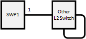 | A loop is detected when the device receives the LDF that it has transmitted.
|
| 2 | 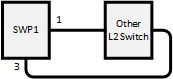 | When loops are detected in multiple ports on the same terminal, the port with the largest number is blocked.
|
| 3 | 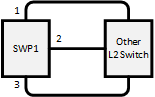 | The loop is avoided by blocking multiple ports. The blocking port is selected using the same rules as case 2.
|
| 4 | 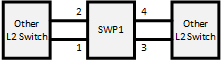 | When loops are detected in multiple groups, the port with the largest number in each group is blocked.
|
| 5 | 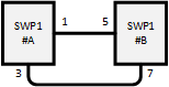 | When a loop occurs between two switches, one of the switches detects the loop. ○When detected in ge3 of switch #A
○When detected in ge7 of switch #B
|
| 6 | 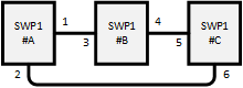 | Out of the six ports that are connected by cable, the port for which the loop is most quickly detected is the one that is blocked. ○When detected in ge2 of switch #A
○When detected in ge4 of switch #B
○When detected in ge6 of switch #C
|
| 7 | 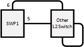 | The LDF transmitted from each port will return to these ports, and ge5 and ge6 will both shut down.
|
| 8 | 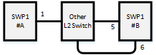 | ge6 of switch #B is blocked. Depending on the timing, ge1 of switch #A will shut down; but the loop in ge1 of switch #A is resolved by blocking ge6 of switch #B.
|
4 Related Commands
The related commands are shown below.
For details on the commands, refer to the Command Reference.
List of related commands
| Operations | Operating commands |
|---|---|
| Enable/disable loop detection function (system) | loop-detect enable |
| Enable/disable loop detection function (LAN/SFP port) | loop-detect enable |
| Set port blocking for loop detection | loop-detect blocking |
| Reset loop detection status | loop-detect reset |
| Refer to the setting status of loop detection | show loop-detect |
5 Examples of Command Execution
This example detects any loops occurring on the L2 switch using the following configuration, when the loop detection function is enable.
- Example 1: Loop occurring in this L2 switch
- Example 2: Loop occurring in a third-party hub connected to this L2 switch
- This sets LAN ports #1 and #2 to detect loops.
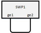
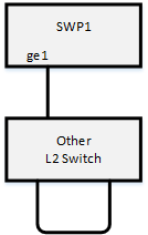
- Enable the loop detection function for the entire system.
L2SW(config)# loop-detect enable ... (Enable the loop detection function for the entire system.)
- Enable the loop detection function for LAN ports #1 and #2.
L2SW(config)# interface ge1
L2SW(config-if)# spanning-tree disable       ... (Enable spanning tree for each LAN port.)
L2SW(config-if)# loop-detect enable          ... (Enable the loop detection function for each LAN port.)
L2SW(config-if)# loop-detect blocking        ... (Enable the blocking function.)
(Also specify the above setting to LAN port #2.)
- The loop detection function for each LAN port and blocking are both enabled by default, so there is no need to set them.
- Confirm that the loop detection function has been set.
Confirm whether the loop detection function is enabled(*) for LAN ports #1 and #2.
SWP1>show loop-detect
loop-detect: Enable

port      loop-detect    port-blocking           status
-------------------------------------------------------
ge1            enable(*)        enable           Normal
ge2            enable(*)        enable           Normal
ge3            enable           enable           Normal
ge4            enable           enable           Normal
ge5            enable           enable           Normal
ge6            enable           enable           Normal
ge7            enable           enable           Normal
ge8            enable           enable           Normal
ge9            enable           enable           Normal
-------------------------------------------------------
(*): Indicates that the feature is enabled.
- If a loop has been detected, the loop detection status can be checked.
- In the case of example 1:
SWP1>show loop-detect
loop-detect: Enable

port      loop-detect    port-blocking           status
-------------------------------------------------------
ge1            enable(*)        enable         Detected    ... (The status of the LAN port #1 is "Detected".)
ge2            enable(*)        enable         Blocking    ... (The status of the LAN port #2 is "Blocking".)
ge3            enable           enable           Normal
ge4            enable           enable           Normal
ge5            enable           enable           Normal
ge6            enable           enable           Normal
ge7            enable           enable           Normal
ge8            enable           enable           Normal
ge9            enable           enable           Normal
-------------------------------------------------------
(*): Indicates that the feature is enabled.
- In the case of example 2:
SWP1>show loop-detect
loop-detect: Enable

port      loop-detect    port-blocking           status
-------------------------------------------------------
ge1            enable(*)        enable         Shutdown    ... (The status of the LAN port #1 is "Shutdown".)
ge2            enable(*)        enable           Normal
ge3            enable           enable           Normal
ge4            enable           enable           Normal
ge5            enable           enable           Normal
ge6            enable           enable           Normal
ge7            enable           enable           Normal
ge8            enable           enable           Normal
ge9            enable           enable           Normal
-------------------------------------------------------
(*): Indicates that the feature is enabled.
- In the case of example 1:
6 Points of Caution
None
7 Related Documentation
- SWP1 Series Technical Data (Basic Functions)
- IP multicast functions
IGMP Snooping
1 Function Overview
IGMP snooping is a function to suppress consumption of network bandwidth in a VLAN environment, by controlling any surplus multicast flooding.
On an L2 switch, since multicast packets are distributed per VLAN, if there is even one device in the VLAN that wants to receive the multicast packet, the packet will be distributed to all ports within the same VLAN.
Operations during multicast distribution (no IGMP snooping)
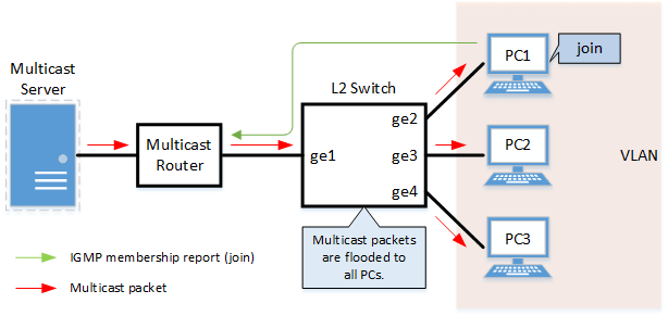
When using the IGMP snooping function, the IGMP messages exchanged between the receiving device and the multicast router are monitored (snooped), the packet from the relevant group will only be distributed to the port, to which the device that wants to receive the multicast packet is connected.
Operations during multicast distribution (using IGMP snooping)
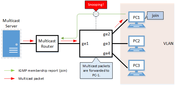
2 Definition of Terms Used
- IGMP (Internet Group Management Protocol)
This is a protocol to control multicast groups.
The multicast router can determine which hosts on the LAN are members of the multicast network, and the hosts can communicate which multicast group they belong to.
There are three protocol versions, IGMPv1 (RFC1112), IGMPv2 (RFC2236), and IGMPv3 (RFC3376).
- Multicast router port
This is the LAN/SFP port to which the multicast router is connected.
The LAN/SFP port that receives the IGMP general query is automatically acquired as the multicast router port.
- IGMP report control function
This is a function where the L2 switch controls the data transmission load between the multicast router and the hosts.
The messages gathered by this L2 switch to perform control are shown below.
- IGMP reports replied to IGMP general queries by hosts, sent from the multicast router
- IGMP leave messages notified by the host
The report control function works with IGMPv1/v2/v3.
- IGMPv2 Fast-Leave function
This function allows for the LAN/SFP port that received a IGMP leave message to immediately stop receiving multicasts (deleting the necessary FDB entry).
Previously, when an IGMP leave message has been received as part of the IGMPv2 leave processing, a group-specific query was sent to check for a receiver.
However, when fast leave is enabled, this operation will not be performed.
For this reason, the fast-leave function is only effective when there is a single receiver under the control of the LAN/SFP port.
- IGMP query transmission function (IGMP Querier)
This is a function to send IGMP general and specific queries.
It is used to make IGMP snooping function in an environment without a multicast router.
3 Function Details
The operating specifications for IGMP snooping are shown below.
- This L2 switch offers snooping functions compatible with IGMP v1/v2/v3.
Later versions to function on this L2 switch can be set using the "igmp snooping version" command.
Version settings are made on the VLAN interface, and initial settings are for v3.
The difference in operations between the configured version and received frame versions are shown in the table below.
- If an IGMP query whose version is higher than the settings is received, the configured version will be lowered, and the query will be forwarded.
- If an IGMP report whose version is higher than the settings is received, the relevant report will not be forwarded, and will be discarded.
- The settings to Enable/disable IGMP snooping are made on the VLAN interface.
The default value for this setting is determined according to the presets when first booting the unit up. (Refer to Maintenance and operation functions:List of preset settings .)
- The default VLAN interface value that was newly generated is "enable".
- The IGMP snooping function can handle the following four operations.
- Multicast router port setting
- IGMP report control
- IGMPv2 fast-leave
- IGMP query transmission
- Although the multicast router port is automatically acquired on VLAN interfaces where IGMP snooping is set to "enable", the "igmp snooping mrouter interface" command is used for static settings.
The "show igmp snooping mrouter" command is used to check multicast router ports that are set on the VLAN interface.
- The IGMP report control function is automatically enabled on VLAN interfaces for which IGMP snooping has been set to "enable".
The IGMP report control function cannot be disabled.
When transmitting an IGMP report or IGMP leave message using the report control function, the IPv4 address allocated to the VLAN interface will be used for the source IPv4 address.
(The address will be set and transmitted as "0.0.0.0" if it has not been allocated.)
- The IGMPv2 fast-leave function is set on the VLAN interface using the "igmp snooping fast-leave" command.
The default value for this setting is "disable" for all VLAN interfaces.
- IGMP snooping is used in environments that do not have a multicast router, and the IGMP query transmission function is used.
The IGMP query transmission function controls the following two parameters.
- IGMP query transmission function Enable/disable
- The "igmp snooping querier" command is used for VLAN interfaces.
- The default value for this setting is determined according to the presets when first booting the unit up. (Refer to Maintenance and operation functions:List of preset settings .)
- The default VLAN interface value that was newly generated is "disable".
- IGMP query transmission interval
- This is executed using the "igmp snooping query-interval" command.
- The transmission interval can be set from 20–18,000 sec., and the default value is 125 sec.
- IGMP query transmission function Enable/disable
- When multiple devices transmit queries in the VLAN, the query is sent by the device with the smallest IPv4 address in the VLAN.
When this L2 switch receives a query containing an IPv4 address that is smaller than its own from a device, the query transmission function will be halted.
The source iPv4 address that is set when a query is transmitted uses the IPv4 address allocated to the VLAN interface. If an IPv4 address has not been allocated, an IPv4 address allocated to a different VLAN interface is used instead.(If no IPv4 addresses have been allocated to any VLAN interfaces, the address will be set and transmitted as "0.0.0.0".)
- This L2 switch features a function that forces the TTL value of a received IGMP packet to change to "1" if the TTL value is invalid (a value other than "1"), instead of discarding the packet.
This is defined as the "TTL check function", and it can be configured using the "igmp snooping check ttl" command for a VLAN interface.
The default value for the TTL check function is determined according to the presets when first booting the unit up. (Refer to Maintenance and operation functions:List of preset settings.)
- The default VLAN interface value that was newly generated is "enable" (discard packets with invalid TTL values).
4 Related Commands
The related commands are shown below.
For details on the commands, refer to the Command Reference.
List of related commands
| Operations | Operating commands |
|---|---|
| Enable/disable IGMP snooping | igmp snooping |
| Set IGMP snooping fast-leave | igmp snooping fast-leave |
| Multicast router port setting | igmp snooping mrouter interface |
| Set query transmission function | igmp snooping querier |
| Set IGMP query transmission interval | igmp snooping query-interval |
| Set IGMP snooping TTL check | igmp snooping check ttl |
| Set IGMP version | igmp snooping version |
| Show multicast router port information | show igmp snooping mrouter |
| Show IGMP multicast recipient information | show igmp snooping groups |
| Show an interface's IGMP-related information | show igmp snooping interface |
| Clear IGMP group membership entries | clear igmp snooping |
5 Examples of Command Execution
5.1 IGMP snooping settings (with multicast router)
In this example, the IGMP snooping function on an environment with a multicast router is enabled, to distribute data to only PC1 and PC3 in the multicast group.
IGMP snooping setting example (with multicast router)

- LAN ports #1–#4 are set as access ports, and associated with VLAN #10.
- Since there is a multicast router, the IGMP query transmission function is left as "disabled".
- Multicast router port acquisition is set to automatic acquisition only.(A static setting is not used.)
- The IGMPv2 fast-leave function is enabled.
- Define VLAN #10, and set IGMP snooping.
L2SW(config)# vlan database
L2SW(config-vlan)# vlan 10                ... (Set VLAN #10.)
L2SW(config-vlan)# exit
L2SW(config)# interface vlan0.10
L2SW(config-if)# igmp snooping            ... (Enable IGMP snooping for VLAN #10.)
L2SW(config-if)# no igmp snooping querier ... (Disable the IGMP query transmission function for VLAN #10.)
L2SW(config-if)# igmp snooping fast-leave ... (Enables IGMP snooping fast-leave for VLAN #10.)
- Set LAN ports #1–#4 as access ports, and associate them with VLAN #10.
L2SW(config)# interface ge1
L2SW(config-if)# switchport mode access
L2SW(config-if)# switchport access vlan 10
(Also specify the above setting to LAN port #2-#4.)
- Confirm the multicast router port information.(It should be connected to LAN port #1.)
L2SW# show igmp snooping mrouter vlan0.10
VLAN     Interface
10        ge1
- Confirm the information for the multicast recipient.
L2SW# show igmp snooping groups
IGMP Connected Group Membership
Group Address    Interface            Uptime   Expires  Last Reporter
239.0.0.1        ge2                  00:00:13 00:00:41 192.168.100.2
239.0.0.1        ge4                  00:00:02 00:00:48 192.168.100.4
5.2 IGMP snooping settings (without multicast router)
In this example, the IGMP snooping function on an environment without a multicast router is enabled, to distribute data to only PC1 and PC3 in the multicast group.
IGMP snooping settings (without multicast router)

- Switch #A
- LAN ports #1–#2 are set as access ports, and associated with VLAN #10.
- The IGMP query transmission function is enabled.
The IGMP query transmission interval is set to 20 sec.
- Switch #B
- LAN ports #1–#4 are set as access ports, and associated with VLAN #10.
- Multicast router port acquisition is set to automatic acquisition only.(A static setting is not used.)
- The IGMPv2 fast-leave function is enabled.
- Since there is a device on which an invalid TTL value has been set for an IGMP packet, disable the TTL check function.
- [Switch #A] Define VLAN #10, and set IGMP snooping.
L2SW(config)# vlan database
L2SW(config-vlan)# vlan 10                       ... (Set VLAN #10.)
L2SW(config-vlan)# exit
L2SW(config)# interface vlan0.10
L2SW(config-if)# igmp snooping                   ... (Enable IGMP snooping for VLAN #10.)
L2SW(config-if)# igmp snooping querier           ... (Disable the IGMP query transmission function for VLAN #10.)
L2SW(config-if)# igmp snooping query-interval 20 ... (Set the VLAN #10 query transmission interval to 20 seconds.)
- [Switch #A] Set LAN ports #1–#2 as access ports, and associate them with VLAN #10.
L2SW(config)# interface ge1
L2SW(config-if)# switchport mode access
L2SW(config-if)# switchport access vlan 10
(Also specify the above setting to LAN port #2.)
- [Switch #B] Define VLAN #10, and set IGMP snooping.
L2SW(config)# vlan database
L2SW(config-vlan)# vlan 10                   ... (Set VLAN #10.)
L2SW(config-vlan)# exit
L2SW(config)# interface vlan0.10
L2SW(config-if)# igmp snooping               ... (Enable IGMP snooping for VLAN #10.)
L2SW(config-if)# no igmp snooping querier    ... (Disable the IGMP query transmission function for VLAN #10.)
L2SW(config-if)# no igmp snooping check ttl  ... (Disable the TTL check function for VLAN #10.)
L2SW(config-if)# igmp snooping fast-leave    ... (Enables IGMP snooping fast-leave for VLAN #10.)
- [Switch #B] Set LAN ports #1–#4 as access ports, and associate them with VLAN #10.
L2SW(config)# interface ge1
L2SW(config-if)# switchport mode access
L2SW(config-if)# switchport access vlan 10
(Also specify the above setting to LAN port #2-#4.)
- [Switch #B] Confirm the information for the multicast recipient.(It should be connected to LAN port #1.)
L2SW# show igmp snooping mrouter vlan0.10
VLAN     Interface
10        ge1
- [Switch #B] Confirm the information for the multicast recipient.
L2SW# show igmp snooping groups
IGMP Connected Group Membership
Group Address    Interface            Uptime   Expires  Last Reporter
239.0.0.1        ge2                  00:00:13 00:00:41 192.168.100.2
239.0.0.1        ge4                  00:00:02 00:00:48 192.168.100.4
6 Points of Caution
None
7 Related Documentation
MLD Snooping
1 Function Overview
MLD snooping is a function to suppress consumption of network bandwidth in an IPv6 VLAN environment, by controlling any surplus multicast flooding.
On an L2 switch, since multicast packets are distributed per VLAN, if there is even one device in the VLAN that wants to receive the multicast packet, the packet will be distributed to all ports within the same VLAN.
Operations during multicast distribution (no MLD snooping)
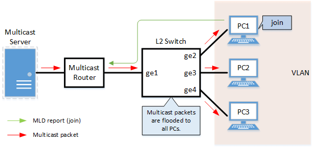
When using the MLD snooping function, the MLD messages exchanged between the receiving device and the multicast router are monitored (snooped), the packet from the relevant group will only be distributed to the port, to which the device that wants to receive the multicast packet is connected.
Operations during multicast distribution (using MLD snooping)
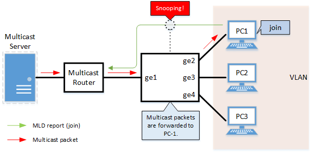
2 Definition of Terms Used
- MLD (Multicast Listener Discovery)
This is a protocol to control multicast groups for IPv6 (an ICMPv6 sub-protocol).
The multicast router can determine which hosts on the LAN are members of the multicast network, and the hosts can communicate which multicast group they belong to.
There are two protocol versions, MLDv1 (RFC2710), and MLDv2 (RFC3810).
- Multicast router port
This is the LAN/SFP port to which the multicast router is connected.
The LAN/SFP port that receives the MLD general query is automatically acquired as the multicast router port.
- MLD report control function
This is a function where the L2 switch controls the data transmission load between the multicast router and the hosts.
The messages gathered by this L2 switch to perform control are shown below.
- MLD reports replied to MLD general queries by hosts, sent from the multicast router
- MLD Done messages and MLD reports notified by the host (leave)
The report control function works with MLDv1/v2.
- MLD Fast Leave function
This function allows for the LAN/SFP port that received an MLDv1 Done message and an MLDv2 report (leave) message to immediately stop receiving multicasts (deleting the necessary FDB entry).
Previously, when an MLDv1 Done message and MLDv2 Report (leave) message has been received as part of the MLD leave processing, a group-specific query was sent to check for a receiver. However, this does not operate when the fast-leave function is enabled.
For this reason, the fast-leave function is only effective when there is a single receiver under the control of the LAN/SFP port.
- MLD query transmission function (MLD Querier)
This is a function to send MLD general and specific queries.
It is used to make MLD snooping work in an environment without a multicast router.
3 Function Details
The operating specifications for MLD snooping are shown below.
- This L2 switch offers snooping functions compatible with MLD v1/v2.
Later versions to function on this L2 switch can be set using the "mld snooping version" command.
Version settings are made on the VLAN interface, and initial settings are for v2.
The difference in operations between the configured version and received frame versions are shown in the table below.
- If an MLD query whose version is higher than the settings is received, the configured version will be lowered, and the query will be forwarded.
- If an MLD report whose version is higher than the settings is received, the relevant report will not be forwarded, and will be discarded.
- The settings to Enable/disable MLD snooping are made on the VLAN interface.
Both the default settings for the default VLAN (VLAN #1) and the default settings after generating the VLAN are enabled.
- The MLD snooping function can handle the following four operations.
- Multicast router port setting
- MLD report control
- MLD fast-leave
- MLD query transmission
- Although the multicast router port is automatically acquired on VLAN interfaces where MLD snooping is set to "enable", the "mld snooping mrouter interface" command is used for static settings.
The "show mld snooping mrouter" command is used to check multicast router ports that are set on the VLAN interface.
- The MLD report control function is automatically enabled on VLAN interfaces for which MLD snooping has been set to "enable".
The MLD report control function cannot be disabled.
When transmitting an MLD report or MLD Done message using the report control function, the IPv6 link local address allocated to the VLAN interface will be used for the source IPv6 address.
(The address will be set and transmitted as "::" if it has not been allocated.)
- The MLD fast-leave function is set on the VLAN interface using the "mld snooping fast-leave" command.
Both the default settings for the default VLAN (VLAN #1) and the default settings after generating the VLAN are disabled.
- MLD snooping is used in environments that do not have a multicast router, and the MLD query transmission function is used.
The MLD query transmission function controls the following two parameters.
- MLD query transmission function enable/disable
- The "mld snooping querier" command is used for VLAN interfaces.
- Both the default settings for the default VLAN (VLAN #1) and the default settings after generating the VLAN are disabled.
- MLD query transmission interval
- This is executed using the "mld snooping query-interval" command.
- The transmission interval can be set from 20–18,000 sec., and the default value is 125 sec.
- MLD query transmission function enable/disable
- When multiple devices transmit queries in the VLAN, the query is sent by the device with the smallest IPv6 address in the VLAN.
When this L2 switch receives a query containing an IPv6 address that is smaller than its own from a device, the query transmission function will be halted.
The source IPv6 address that is set when a query is transmitted uses the IPv6 link local address allocated to the VLAN interface. If an IPv6 address has not been allocated, an IPv6 link local address allocated to a different VLAN interface is used instead.
(If no IPv6 link local addresses have been allocated to any VLAN interfaces, no address will be transmitted.)
4 Related Commands
The related commands are shown below.
For details on the commands, refer to the Command Reference.
List of related commands
| Operations | Operating commands |
|---|---|
| Enable/disable MLD snooping | mld snooping |
| Set MLD snooping fast-leave | mld snooping fast-leave |
| Multicast router port setting | mld snooping mrouter interface |
| Set query transmission function | mld snooping querier |
| Set MLD query transmission interval | mld snooping query-interval |
| Set MLD version | mld snooping version |
| Show multicast router port information | show mld snooping mrouter |
| Show MLD multicast recipient information | show mld snooping groups |
| Show an interface's MLD-related information | show mld snooping interface |
| Clear MLD group membership entries | clear mld snooping |
5 Examples of Command Execution
5.1 MLD snooping settings (with multicast router)
In this example, the MLD snooping function on an environment with a multicast router is enabled, to distribute data to only PC1 and PC3 that has joined the multicast group.
MLD snooping setting example (with multicast router)
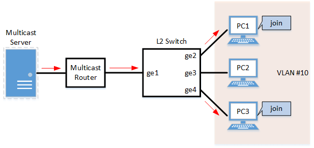
- LAN ports #1–#4 are set as access ports, and associated with VLAN #10.
- Since there is a multicast router, the MLD query transmission function is left as "disabled".
- Multicast router port acquisition is set to automatic acquisition only.(A static setting is not used.)
- The MLD fast-leave function is enabled.
- Define VLAN #10, and set MLD snooping.
L2SW(config)# vlan database
L2SW(config-vlan)#vlan 10               ... (Set VLAN #10.)
L2SW(config-vlan)#exit
L2SW(config)#interface vlan0.10
L2SW(config-if)#ipv6 enable             ... (Enable IPv6 for VLAN #10.)
L2SW(config-if)#mld snooping            ... (Enable MLD snooping for VLAN #10.)
L2SW(config-if)#no mld snooping querier ... (Disable the MLD query transmission function for VLAN #10.)
L2SW(config-if)#mld snooping fast-leave ... (Enable MLD snooping fast-leave for VLAN #10.)
- Since this MLD snooping is enabled and the MLD query transmission function is disabled by default, there is no need to make this setting.
- Set LAN ports #1–#4 as access ports, and associate them with VLAN #10.
L2SW(config)# interface ge1
L2SW(config-if)# switchport mode access
L2SW(config-if)# switchport access vlan 10
(Also specify the above setting to LAN port #2-#4.)
- Confirm the multicast router port information.(It should be connected to LAN port #1.)
L2SW#show mld snooping mrouter vlan0.10
VLAN     Interface
10        ge1
- Confirm the information for the multicast recipient.
L2SW#show mld snooping groups
MLD Connected Group Membership
Group Address                           Interface            Uptime   Expires  Last Reporter
ff15::1:1                               ge2                  00:00:13 00:00:41 fe80::a00:27ff:fe8b:87e2
ff15::1:1                               ge4                  00:00:02 00:00:48 fe80::a00:27ff:fe8b:87e4
5.2 MLD snooping settings (without multicast router)
In this example, the MLD snooping function on an environment without a multicast router is enabled, to distribute data to only PC1 and PC3 that has joined the multicast group.
MLD snooping settings (without multicast router)
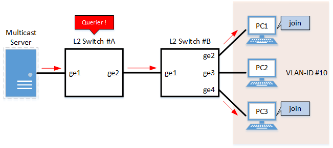
- Switch #A
- LAN ports #1–#2 are set as access ports, and associated with VLAN #10.
- The MLD query transmission function is enabled.
The MLD query transmission interval is set to 20 sec.
- Switch #B
- LAN ports #1–#4 are set as access ports, and associated with VLAN #10.
- Multicast router port acquisition is set to automatic acquisition only.(A static setting is not used.)
- The MLD fast-leave function is enabled.
- [Switch #A] Define VLAN #10, and set MLD snooping.
L2SW(config)# vlan database
L2SW(config-vlan)#vlan 10                      ... (Set VLAN #10.
L2SW(config-vlan)#exit
L2SW(config)#interface vlan0.10
L2SW(config-if)#ipv6 enable                    ... (Enable IPv6 for VLAN #10.)
L2SW(config-if)#mld snooping                   ... (Enable MLD snooping for VLAN #10.)
L2SW(config-if)#mld snooping querier           ... (Enable the MLD query transmission function for VLAN #10.)
L2SW(config-if)#mld snooping query-interval 20 ... (Set the VLAN #10 query transmission interval to 20 seconds.)
- Since MLD snooping is enabled by default, there is no need to make this setting.
- [Switch #A] Set LAN ports #1–#2 as access ports, and associate them with VLAN #10.
L2SW(config)# interface ge1
L2SW(config-if)# switchport mode access
L2SW(config-if)# switchport access vlan 10
(Also specify the above setting to LAN port #2.)
- [Switch #B] Define VLAN #10, and set MLD snooping.
L2SW(config)# vlan database
L2SW(config-vlan)#vlan 10                  ... (Set VLAN #10.)
L2SW(config-vlan)#exit
L2SW(config)#interface vlan0.10
L2SW(config-if)#ipv6 enable                ... (Enable IPv6 for VLAN #10.)
L2SW(config-if)#mld snooping               ... (Enable MLD snooping for VLAN #10.)
L2SW(config-if)#no mld snooping querier    ... (Disable the MLD query transmission function for VLAN #10.)
L2SW(config-if)#mld snooping fast-leave    ... (Enable MLD snooping fast-leave for VLAN #10.)
- Since this MLD snooping is enabled and the MLD query transmission function is disabled by default, there is no need to make this setting.
- [Switch #B] Set LAN ports #1–#4 as access ports, and associate them with VLAN #10.
L2SW(config)# interface ge1
L2SW(config-if)# switchport mode access
L2SW(config-if)# switchport access vlan 10
(Also specify the above setting to LAN port #2-#4.)
- [Switch #B] Confirm the information for the multicast recipient.(It should be connected to LAN port #1.)
L2SW#show mld snooping mrouter vlan0.10
VLAN     Interface
10        ge1
- [Switch #B] Confirm the information for the multicast recipient.
L2SW#show mld snooping groups
MLD Connected Group Membership
Group Address                           Interface            Uptime   Expires  Last Reporter
ff15::1:1                               ge2                  00:00:13 00:00:41 fe80::a00:27ff:fe8b:87e2
ff15::1:1                               ge4                  00:00:02 00:00:48 fe80::a00:27ff:fe8b:87e4
6 Points of Caution
The MLD snooping function can be used from Rev.2.01.04 upwards.
Be aware that older versions than this will not be able to use this function.
When enabling the MLD snooping function, be aware of the IPv6 multicast address used.
The beginning of the MAC address for the IPv6 multicast address is fixed at “3333”, and the digits afterwards are unchanged from the lower 32 bits of the IPv6 multicast address.
For example, if an IPv6 multicast address of “ff15::1” is used, the MAC address that is registered in the FDB will be “3333.0000.0001”. However, since this MAC address is the same as the all-nodes multicast address “ff02::1”, flooding will not occur with packets that have a destination of “ff02::1”.
Because of this, problems will occur, such as RA (router advertisements) being forwarded only to specific devices.
7 Related Documentation
- SWP1 Series Technical Data (Basic Functions)
- Traffic control
ACL
1 Function Overview
The access list (ACL) is a conditional statement that determines whether to permit or to deny the frame.
If the access list is applied to the interface, only the permitted frame will be transferred, and the denied frame will be discarded.
As this allows for only specified frames to be selected for transfer, this feature is primarily used for security purposes.
This L2 switch supports four access list types, as shown in the table below.
Access list type
| Access list type | Deciding criteria | Access list ID | Purpose of use |
|---|---|---|---|
| Standard IPv4 access list | Source IPv4 address | 1–99 1300–1999 | Filters access from specific hosts and networks. |
| Extended IPv4 access list | Source IPv4 address Destination IPv4 address IP protocol type | 100–199 2000–2699 | Filters specific IP protocol types such as TCP/UDP, as well as hosts and networks. |
| IPv6 access list | Source IPv6 address | 3000–3699 | Filters access from specific hosts and networks. |
| MAC access list | Source MAC address Destination MAC address | 100–199 2000–2699 | Filters access and data transfer from specific devices. |
- Extended IPv4 access list ID and MAC access list ID are shared
2 Definition of Terms Used
- ACL
Abbreviation of "Access Control List".
- Wildcard mask
This information specifies which part of the specified IPv4 address and MAC address will be read. This is used when specifying the IPv4 address and MAC address ranges with the ACL conditions.
- When the wildcard mask bit is "0": check the relevant bit
- When the wildcard mask bit is "1": do not check the relevant bit
Below is an example of settings using a wildcard mask. (The underlined portion is the wildcard mask.)
- When specifying conditions for subnet 192.168.1.0/24: 192.168.1.0 0.0.0.255 (specified in decimals)
- When specifying conditions for vendor code 00-A0-DE-*-*-*: 00A0.DE00.0000 0000.00FF.FFFF (specified in hexadecimal)
3 Function Details
3.1 Generating an access list
Access lists for the number of IDs in each access list number can be generated. (Refer to the table in “1 Function Overview”.)
A maximum of 39 control parameters can be registered per list for access lists.
However, the "Discard All" parameter will be automatically added as an action if the registered control parameters have not been satisfied. (This is called "implicit denial".)
3.2 Applying to the interface
The status of access list application to this L2 switch input/output interface is shown in the table below.
Note that one access list can be applied to the IN and OUT respectively for the interface.
Status of access list application to the interface
| Access list type | LAN/SFP port | VLAN interface | Static/LACP logical interface | |||
|---|---|---|---|---|---|---|
| in | out | in | out | in | out | |
| Standard IPv4 access list | ✓ | ✓ | ✓ | - | - | - |
| Extended IPv4 access list | ✓ | ✓(*) | ✓ | - | - | - |
| IPv6 access list | ✓ | ✓ | ✓ | - | - | - |
| MAC access list | ✓ | - | ✓ | - | - | - |
(*)As a limitation, the extended IPv4 access list that specifies the port number range cannot be applied to the interface output (out) side.
The number of access lists that can be applied to the interface depends on the number of control parameters that are registered in the access lists.
On this L2 switch, a maximum of 512 control parameters can be registered to the interface.
Applying an access list to the interface will use resources, equivalent to the number of control parameters that are registered to the access list.
- As an example, if an access list with five registered control parameters is applied to the LAN port, there will be 507 control parameters left to register.
However, control parameters may also be used internally within the system in some cases, and use resources accordingly.
3.3 Settings for the LAN/SFP ports
The steps for applying access lists to the LAN/SFP ports are shown below.
- Decide on the filtering parameters, and generate the access list.
- Add a name if necessary.
- Check the access list.
- Apply the access list to the LAN/SFP port.
- Check the access list that was applied.
The following is a list of operating commands.
Access list operating commands (when applying to the LAN/SFP ports)
| Access list type | Access list generation | Access list confirmation | Access list application | Confirmation of applied access list |
|---|---|---|---|---|
| Standard IPv4 access list | access-list | show ip access-list | ip access-group | show running-config access-list |
| Extended IPv4 access list | access-list | show ip access-list | ip access-group | show running-config access-list |
| IPv6 access list | access-list | show ipv6 access-list | ip access-group | show running-config access-list |
| MAC access list | access-list | show mac access-list | mac access-group | show running-config access-list |
3.4 VLAN interface settings
The steps for applying access lists to the VLAN interface are shown below.
- Decide on the filtering parameters, and generate the access list.
- Add a name if necessary.
- Check the access list.
- Generate the VLAN access map.
- Set the access list for the VLAN access map.
- Check the VLAN access map.
- Apply the VLAN access map to the VLAN.
- The operations to apply standard/extended IP access lists and MAC access lists are different.
- Check the VLAN access map that was applied.
The operations in steps 1 and 2 are the same as those shown in 3.3.
The following is a list of operating commands from 3. and on.
VLAN access map operating command
| Access list type | VLAN access map generation | Settings for access list used with VLAN access map | VLAN access map confirmation | VLAN access map application | Confirmation of the applied VLAN access map |
|---|---|---|---|---|---|
| Standard IPv4 access list | vlan access-map | match ip access-list | show vlan access-map | vlan filter | show vlan filter |
| Extended IPv4 access list | vlan access-map | match ip access-list | show vlan access-map | vlan filter | show vlan filter |
| IPv6 access list | vlan access-map | match ip access-list | show vlan access-map | vlan filter | show vlan filter |
| MAC access list | vlan access-map | match mac access-list | show vlan access-map | vlan filter | show vlan filter |
4 Related Commands
The related commands are shown below.
For details on the commands, refer to the Command Reference.
List of related commands
| Operations | Operating commands |
|---|---|
| Generate standard IPv4 access list | access-list |
| Add comment to standard IPv4 access list | access-list remark |
| Apply standard IPv4 access list | ip access-group |
| Generate extended IPv4 access list | access-list |
| Add comment to extended IPv4 access list | access-list remark |
| Apply extended IPv4 access list | ip access-group |
| Generate IPv6 access list | access-list |
| Add comment to IPv6 access list | access-list remark |
| Apply IPv6 access list | ip access-group |
| Generate MAC access list | access-list |
| Add comment to MAC access list | access-list remark |
| Apply MAC access list | mac access-group |
| Show generated standard IPv4 access list | show ip access-list |
| Show generated extended IPv4 access list | show ip access-list |
| Show generated IPv6 access list | show ipv6 access-list |
| Show generated MAC access list | show mac access-list |
| Show generated all access list | show access-list |
| Show MAC access list applied to interface | show mac-access-group |
5 Examples of Command Execution
5.1 Standard IPv4 access list settings
5.1.1 Example of application to a LAN port
■Specifying the host
In this example, we will set LAN port #1 to receive frames only from host: 192.168.1.1.
The access list ID to be used is #2, and the access list name is STD-ACL-EX.
- Generate and confirm access list #2.
L2SW(config)#access-list 2 permit host 192.168.1.1 ... (Create an access list.) L2SW(config)#access-list 2 remark STD-ACL-EX ... (Adds a comment (remark) to access list.) L2SW(config)#end L2SW# L2SW#show ip access-list ... (Shows the access list.) Standard IP access list 2 permit 192.168.1.1 - Apply access list #2 to LAN port #1.
L2SW(config)#interface ge1
L2SW(config-if)#ip access-group 2 in  ... (Apply access list.)
L2SW(config-if)#end
L2SW#
L2SW#show access-group  ... (Apply ACL.)
Interface ge1  : IP access group 2 in
■Specifying a network
In this example, we will set LAN port #1 to receive frames only from network: 192.168.1.0/24.
The access list ID to be used is #2, and the access list name is STD-ACL-EX.
- Generate and confirm access list #2.
L2SW(config)#access-list 2 permit 192.168.1.0 0.0.0.255 ... (Create an access list.) L2SW(config)#access-list 2 remark STD-ACL-EX ... (Adds a comment (remark) to access list.) L2SW(config)#end L2SW# L2SW#show ip access-list ... (Shows the access list.) Standard IP access list 2 permit 192.168.1.0, wildcard bits 0.0.0.255 - Apply access list #2 to LAN port #1.
L2SW(config)#interface ge1
L2SW(config-if)#ip access-group 2 in  ... (Apply access list.)
L2SW(config-if)#end
L2SW#
L2SW#show access-group  ... (Apply ACL.)
Interface ge1  : IP access group 2 in
5.1.2 Example of application to the VLAN interface
■Specifying the host
In this example, we will set VLAN port #1000 to receive frames only from host: 192.168.1.1.
We will use access list ID #2.
The VLAN access map to be used will be VAM-001, and access list #2 will be set.
- Generate and confirm access list #2.
L2SW(config)#access-list 2 permit host 192.168.1.1 ... (Create an access list.) L2SW(config)#end L2SW# L2SW#show ip access-list ... (Shows the access list.) Standard IP access list 2 permit 192.168.1.1 - Generate VLAN access map VAM-001, and set access list #2.
L2SW(config)#vlan access-map VAM-001                 ... (Create a VLAN access map.)
L2SW(config-vlan-access-map)#match ip access-list 2  ... (Specify an access list.)
L2SW(config-vlan-access-map)#end
L2SW#
L2SW#show vlan access-map  ... (Show VLAN access map information.)
VLAN-ACCESS-MAP: VAM-001
 match ip access-list 2
- Apply the VLAN access map VAM-001 to VLAN #1000, and confirm the status.
L2SW(config)#vlan filter VAM-001 1000  ... (Specify VLAN access map for VLAN.)
L2SW(config)#end
L2SW#
L2SW#show vlan filter  ... (Show VLAN access map filter application information.)
Vlan Filter VAM-001 is applied to vlan 1000
■Specifying a network
In this example, we will set VLAN port #1000 to receive frames only from network: 192.168.1.0/24.
We will use access list ID #2.
The VLAN access map to be used will be VAM-001, and access list #2 will be set.
- Generate and confirm access list #2.
L2SW(config)#access-list 2 permit 192.168.1.0 0.0.0.255 ... (Create an access list.) L2SW(config)#end L2SW# L2SW#show ip access-list ... (Shows the access list.) Standard IP access list 2 permit 192.168.1.0, wildcard bits 0.0.0.255 - Generate VLAN access map VAM-001, and set access list #2.
L2SW(config)#vlan access-map VAM-001                 ... (Create a VLAN access map.)
L2SW(config-vlan-access-map)#match ip access-list 2  ... (Specify an access list.)
L2SW(config-vlan-access-map)#end
L2SW#
L2SW#show vlan access-map  ... (Show VLAN access map information.)
VLAN-ACCESS-MAP: VAM-001
 match ip access-list 2
- Apply the VLAN access map VAM-001 to VLAN #1000, and confirm the status.
L2SW(config)#vlan filter VAM-001 1000  ... (Specify VLAN access map for VLAN.)
L2SW(config)#end
L2SW#
L2SW#show vlan filter  ... (Show VLAN access map filter application information.
Vlan Filter VAM-001 is applied to vlan 1000
5.2 Extended IPv4 access list settings
5.2.1 Example of application to a LAN port
■Specifying the host
In this example, we will set LAN port #1 to permit access from host: 192.168.1.1 to host: 10.1.1.1.
The access list ID to be used is #123, and the access list name of EXT-ACL-EX is added.
- Generate and confirm access list #123.
L2SW(config)#access-list 123 permit any host 192.168.1.1 host 10.1.1.1 ... (Create an access list.) L2SW(config)#access-list 123 remark EXT-ACL-EX ... (Adds a comment (remark) to ACL.) L2SW(config)#end L2SW# L2SW#show ip access-list ... (Shows the access list.) Extended IP access list 123 permit any host 192.168.1.1 host 10.1.1.1 L2SW# - Apply access list #123 to LAN port #1.
L2SW(config)#interface ge1
L2SW(config-if)#ip access-group 123 in  ... (Apply access list.)
L2SW(config-if)#end
L2SW#
L2SW#show access-group  ... (Apply ACL.)
Interface ge1  : IP access group 123 in
■Specifying a network
In this example, we will set LAN port #1 to permit access from network: 192.168.1.0/24 to host: 10.1.1.1.
The access list ID to be used is #123, and the access list name of EXT-ACL-EX is added.
- Generate and confirm access list #123.
L2SW(config)#access-list 123 permit any 192.168.1.0 0.0.0.255 host 10.1.1.1 ... (Create an access list.) L2SW(config)#access-list 123 remark EXT-ACL-EX ... (Adds a comment (remark) to ACL.) L2SW(config)#end L2SW# L2SW#show ip access-list ... (Show ACL.) Extended IP access list 123 permit any 192.168.1.0 0.0.0.255 host 10.1.1.1 L2SW# - Apply access list #123 to LAN port #1.
L2SW(config)#interface ge1
L2SW(config-if)#ip access-group 123 in  ... (Apply access list.)
L2SW(config-if)#end
L2SW#
L2SW#show access-group  ... (Apply ACL.)
Interface ge1  : IP access group 123 in
5.2.2 Example of application to the VLAN interface
■Specifying the host
In this example, we will set VLAN #1000 to permit access from host: 192.168.1.1 to host: 10.1.1.1.
We will use access list ID #123.
The VLAN access map to be used will be VAM-002, and access list #123 will be set.
- Generate and confirm access list #123.
L2SW(config)#access-list 123 permit any host 192.168.1.1 host 10.1.1.1 ... (Create an access list.) L2SW(config)#end L2SW# L2SW#show ip access-list ... (Shows the access list.) Extended IP access list 123 permit any host 192.168.1.1 host 10.1.1.1 - Generate VLAN access map VAM-002, and set access list #123.
L2SW(config)#vlan access-map VAM-002                   ... (Create a VLAN access map.)
L2SW(config-vlan-access-map)#match ip access-list 123  ... (Register ACL.)
L2SW(config-vlan-access-map)#end
L2SW#
L2SW#show vlan access-map  ... (Show VLAN access map information.)
VLAN-ACCESS-MAP: VAM-002
 match ip access-list 123
- Apply the VLAN access map VAM-002 to VLAN #1000, and confirm the status.
L2SW(config)#vlan filter VAM-002 1000  ... (Specify VLAN access map for VLAN.)
L2SW(config)#end
L2SW#
L2SW#show vlan filter  ... (Show VLAN access map filter application information.)
Vlan Filter VAM-002 is applied to vlan 1000
■Specifying a network
In this example, we will set VLAN port #1000 to permit access from network: 192.168.1.0/24 to host: 10.1.1.1.
We will use access list ID #123.
The VLAN access map to be used will be VAM-002, and access list #2 will be set.
- Generate and confirm access list #123.
L2SW(config)#access-list 123 permit any 192.168.1.0 0.0.0.255 host 10.1.1.1 ... (Create an access list.) L2SW(config)#end L2SW# L2SW#show ip access-list ... (Shows the access list.) Extended IP access list 123 permit any 192.168.1.0 0.0.0.255 host 10.1.1.1 - Generate VLAN access map VAM-002, and set *access list #123*.
L2SW(config)#vlan access-map VAM-002                   ... (Create a VLAN access map.)
L2SW(config-vlan-access-map)#match ip access-list 123  ... (Register ACL.)
L2SW(config-vlan-access-map)#end
L2SW#
L2SW#show vlan access-map  ... (Show VLAN access map information.)
VLAN-ACCESS-MAP: VAM-002
 match ip access-list 123
- Apply the VLAN access map VAM-002 to VLAN #1000, and confirm the status.
L2SW(config)#vlan filter VAM-002 1000  ... (Specify VLAN access map for VLAN.)
L2SW(config)#end
L2SW#
L2SW#show vlan filter  ... (Show VLAN access map filter application information.)
Vlan Filter VAM-002 is applied to vlan 1000
5.3 IPv6 access list settings
5.3.1 Example of application to a LAN port
■Specifying the host
In this example, we will set LAN port #1 to receive frames only from host: 2001:db8::1.
The access list ID to be used is #3000, and the access list name is IPV6-ACL-EX.
- Generate and confirm access list #3000.
L2SW(config)#access-list 3000 permit 2001:db8::1/128 ... (Create an access list.) L2SW(config)#access-list 3000 remark IPV6-ACL-EX ... (Adds a comment (remark) to ACL.) L2SW(config)#end L2SW# show ipv6 access-list ... (Shows the access list.) IPv6 access list 3000 permit 2001:db8::1/128 - Apply access list #3000 to LAN port #1.
L2SW(config)#interface ge1
L2SW(config-if)#ip access-group 3000 in  ... (Apply access list.)
L2SW(config-if)#end
L2SW#
L2SW#show access-group  ... (Apply ACL.)
Interface ge1  : IPv6 access group 3000 in
■Specifying a network
In this example, we will set LAN port #1 to receive frames only from network: 2001:db8::/64.
The access list ID to be used is #3000, and the access list name is IPV6-ACL-EX.
- Generate and confirm access list #3000.
L2SW(config)#access-list 3000 permit 2001:db8::/64 ... (Create an access list.) L2SW(config)#access-list 3000 remark IPV6-ACL-EX ... (Adds a comment (remark) to ACL.) L2SW(config)#end L2SW# show ipv6 access-list ... (Shows the access list. IPv6 access list 3000 permit 2001:db8::/64 - Apply access list #3000 to LAN port #1.
L2SW(config)#interface ge1
L2SW(config-if)#ip access-group 3000 in  ... (Apply access list.)
L2SW(config-if)#end
L2SW#
L2SW#show access-group  ... (Apply ACL.)
Interface ge1  : IPv6 access group 3000 in
5.3.2 Example of application to the VLAN interface
■Specifying the host
In this example, we will set VLAN #1000 to receive frames only from host: 2001:db8::1.
We will use access list ID #3000.
The VLAN access map to be used will be VAM-001, and access list #3000 will be set.
- Generate and confirm access list #3000.
L2SW(config)#access-list 3000 permit 2001:db8::1/128 ... (Create an access list.) L2SW(config)#end L2SW# L2SW#show ipv6 access-list ... (Shows the access list.) IPv6 access list 3000 permit 2001:db8::1/128 - Generate VLAN access map VAM-001, and set access list #3000.
L2SW(config)#vlan access-map VAM-001                    ... (Create a VLAN access map.)
L2SW(config-vlan-access-map)#match ip access-list 3000  ... (Specify an access list.)
L2SW(config-vlan-access-map)#end
L2SW#
L2SW#show vlan access-map  ... (Show VLAN access map information.)
VLAN-ACCESS-MAP: VAM-001
 match ip access-list 3000
- Apply the VLAN access map VAM-001 to VLAN #1000, and confirm the status.
L2SW(config)#vlan filter VAM-001 1000  ... (Specify VLAN access map for VLAN.)
L2SW(config)#end
L2SW#
L2SW#show vlan filter  ... (Show VLAN access map filter application information.)
Vlan Filter VAM-001 is applied to vlan 1000
■Specifying a network
In this example, we will set VLAN port #1000 to receive frames only from network: 2001:db8::/64.
We will use access list ID #3000.
The VLAN access map to be used will be VAM-001, and access list #3000 will be set.
- Generate and confirm access list #3000.
L2SW(config)#access-list 3000 permit 2001:db8::/64 ... (Create an access list.) L2SW(config)#end L2SW# L2SW#show ipv6 access-list ... (Shows the access list.) IPv6 access list 3000 permit 2001:db8::/64 - Generate VLAN access map VAM-001, and set access list #2.
L2SW(config)#vlan access-map VAM-001                    ... (Create a VLAN access map.)
L2SW(config-vlan-access-map)#match ip access-list 3000  ... (Specify an access list.)
L2SW(config-vlan-access-map)#end
L2SW#
L2SW#show vlan access-map  ... (Show VLAN access map information.)
VLAN-ACCESS-MAP: VAM-001
 match ip access-list 3000
- Apply the VLAN access map VAM-001 to VLAN #1000, and confirm the status.
L2SW(config)#vlan filter VAM-001 1000  ... (Specify VLAN access map for VLAN.)
L2SW(config)#end
L2SW#
L2SW#show vlan filter  ... (Show VLAN access map filter application information.)
Vlan Filter VAM-001 is applied to vlan 1000
5.4 MAC access list settings
5.4.1 Example of application to a LAN port
■Specifying the host
In this example, we will set LAN port #1 to discard all frames from host: 00-A0-DE-12-34-56, and permit all other frames.
The access list ID to be used is #2000, and the access list name to add is MAC-ACL-EX.
- Generate and confirm access list #2000.
L2SW(config)# access-list 2000 deny mac host 00a0.de12.3456 any ... (Create an access list.) L2SW(config)# access-list 2000 permit mac any any L2SW(config)# access-list 2000 remark MAC-ACL-EX ... (Adds a comment (remark) to ACL.) L2SW(config)# end L2SW# L2SW# show mac access-list ... (Shows the access list.) Extended MAC-ACCESS-LIST: 2000 deny mac host 00a0.de12.3456 any permit mac any any - Apply access list #2000 to LAN port #1.
L2SW(config)#interface ge1
L2SW(config-if)#mac access-group 2000 in  ... (Apply access list.)
L2SW(config-if)#end
L2SW#
L2SW#show access-group  ... (Apply ACL.)
Interface ge1  : MAC access group 2000 in
■Vendor specification
In this example, we will set LAN port #1 to discard all frames from vendor code: 00-A0-DE-*-*-* (00-A0-DE-00-00-00 through 00-A0-DE-FF-FF-FF), and permit all other frames.
The access list ID to be used is #2000, and the access list name of MAC-ACL-EX is added.
- Generate and confirm access list #2000.
L2SW(config)#access-list 2000 deny mac 00a0.de00.0000 0000.00ff.ffff any ... (Create an access list.) L2SW(config)#access-list 2000 permit mac any any L2SW(config)#access-list 2000 remark MAC-ACL-EX ... (Adds a comment (remark) to ACL.) L2SW(config)#end L2SW# L2SW#show mac access-list ... (Shows the access list. Extended MAC-ACCESS-LIST: 2000 deny mac 00A0.DE00.0000 0000.00FF.FFFF any permit mac any any - Apply access list #2000 to LAN port #1.
L2SW(config)#interface ge1
L2SW(config-if)#mac access-group 2000 in  ... (Apply access list.)
L2SW(config-if)#end
L2SW#
L2SW#show access-group  ... (Apply ACL.)
Interface ge1  : MAC access group 2000 in
5.4.2 Example of application to the VLAN interface
■Specifying the host
In this example, we will set VLAN port #1000 to discard all frames from host: 00-A0-DE-12-34-56, and permit all other frames.
We will use access list ID #2000. The access list name will be MAC-ACL-EX.
The VLAN access map to be used will be VAM-003, and access list #2000 will be set.
- Generate and confirm access list #2000.
L2SW(config)#access-list 2000 deny mac host 00a0.de12.3456 any ... (Create access list #2000) L2SW(config)#access-list 2000 permit mac any any L2SW(config)#access-list 2000 remark MAC-ACL-EX ... (Adds a comment (remark) to ACL.) L2SW(config)#end L2SW# L2SW#show mac access-list ... (Shows the access list.) Extended MAC-ACCESS-LIST: 2000 deny mac host 00A0.DE12.3456 any permit mac any any - Generate VLAN access map VAM-003, and set access list #2000.
L2SW(config)# vlan access-map VAM-003                     ... (Create a VLAN access map.)
L2SW(config-vlan-access-map)# match mac access-list 2000  ... (Register ACL.)
L2SW(config-vlan-access-map)# end
L2SW#
L2SW#show vlan access-map  ... (Show VLAN access map information.)
VLAN-ACCESS-MAP: VAM-003
 match ip access-list 2000
- Apply the VLAN access map VAM-003 to VLAN #1000, and confirm the status.
L2SW(config)#vlan filter VAM-003 1000  ... (Specify VLAN access map for VLAN.)
L2SW(config)#end
L2SW#
L2SW#show vlan filter  ... (Show VLAN access map filter application information.)
Vlan Filter VAM-003 is applied to vlan 1000
■Vendor specification
In this example, we will set VLAN port #1000 to discard all frames from vendor code: 00-A0-DE-*-*-* (00-A0-DE-00-00-00 through 00-A0-DE-FF-FF-FF), and permit all other frames.
We will use access list ID #2000. The access list name will be MAC-ACL-EX.
The VLAN access map to be used will be VAM-003, and access list #2000 will be set.
- Generate and confirm access list #2000.
L2SW(config)#access-list 2000 deny mac 00a0.de00.0000 0000.00ff.ffff any ... (Create access list #2000) L2SW(config)#access-list 2000 permit mac any any L2SW(config)#access-list 2000 remark MAC-ACL-EX ... (Adds a comment (remark) to ACL.) L2SW(config)#end L2SW# L2SW#show mac access-list ... (Shows the access list.) Extended MAC-ACCESS-LIST: 2000 deny mac 00A0.DE00.0000 0000.00FF.FFFF any permit mac any any - Generate VLAN access map VAM-003, and set access list #2000.
L2SW(config)# vlan access-map VAM-003                     ... (Create a VLAN access map.)
L2SW(config-vlan-access-map)# match mac access-list 2000  ... (Register ACL.)
L2SW(config-vlan-access-map)# end
L2SW#
L2SW#show vlan access-map  ... (Show VLAN access map information.)
VLAN-ACCESS-MAP: VAM-003
 match ip access-list 2000
- Apply the VLAN access map VAM-003 to VLAN #1000, and confirm the status.
L2SW(config)#vlan filter VAM-003 1000  ... (Specify VLAN access map for VLAN.)
L2SW(config)#end
L2SW#
L2SW#show vlan filter  ... (Show VLAN access map filter application information.)
Vlan Filter VAM-003 is applied to vlan 1000
6 Points of Caution
None
7 Related Documentation
QoS
1 Function Overview
QoS (Quality of Service) is a technology for reserving a specified bandwidth for communications over a network, guaranteeing a fixed speed of communication.
Application data is classified and grouped, and then forwarded by group priority level, referring to the DSCP in the IP header or the CoS in the IEEE802.1Q tag.
2 Definition of Terms Used
- CoS (IEEE 802.1p Class of Service)
This expresses priority as a 3-bit field in the VLAN tag header, with a value from 0–7.
Also called 802.1p user priority.
- IP Precedence
This expresses priority as a 3-bit field in the TOS field of the IP header, with a value from 0–7.
Used to indicate the traffic class of the frame in question, for the device that receives the frame.
- DSCP (Diffserv Code Point)
This expresses priority as a 6-bit field in the TOS field of the IP header, with a value from 0–63.
Since DSCP uses the same TOS field as IP precedence, it is compatible with IP-Precedence.
Used to indicate the traffic class of the frame in question, for the device that receives the frame.
- Default CoS
This is the CoS value that is assigned to an untagged frame for the purpose of internal processing.
- Transmission queue
This L2 switch has eight transmission queues per port. The transmission queues are numbered from ID 0–7, with larger ID numbers being given higher priority.
- Trust mode
Shows what the determination of the transmission queue ID is based on (what is trusted).
The CoS and DSCP values of the received frames can be used for allocation, and priorities set per reception port can be applied.
This can be set per LAN/SFP port, with the default status (QoS enabled) set to "CoS".
- Transmission queue ID conversion table
This is a conversion table used when deciding on the transmission queue ID from either the CoS value or the DSCP value.
There are two kinds of transmission queue ID conversion tables, the CoS-transmission queue ID conversion table and the DSCP-transmission queue ID conversion table. Each kind is used with its own trust mode.
Mapping can be freely changed by the user.
- Port priority
The priority set for each reception port. When trust mode is “port priority”, frames received by that port will be stored in the transmission queue according to the port priority settings.
- Class map
This defines the conditions by which packets are classified into traffic classes.
Packets can be associated and used with policy maps, and QoS processing (pre-marking, transmission queue specification, metering/policing/remarking) per traffic class can be defined.
- Policy map
This is an element for performing a QoS processing series on the reception port. This cannot be used by itself, but rather is associated and used with 1–8 class maps.
When a policy map is applied to a LAN/SFP port, traffic is classified per class map that is associated with the policy map for the packets received on the relevant port.
Also, QoS processing (pre-marking, transmission queue specification, metering/policing/remarking) set per traffic class can be performed.
- Policer
This is a group series of metering/policing/remarking settings.
There are two types of policers, an individual policer for metering that targets one traffic class, and a group policer that meters multiple traffic classes by putting them together.
3 Function Details
3.1 Enable/disable QoS control
The QoS control setting on this L2 switch is enabled by default.
Use the "no mls qos" command to disable QoS control. To enable QoS control, use the "mls qos enable" command.
Almost all of the QoS control commands cannot be executed without enabling QoS.
The QoS function status can be checked using the "show mls qos" command.
3.2 QoS processing flow
The QoS processing flow is shown below.
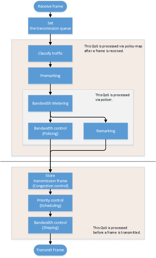
3.3 Assigning the transmission queue
When this L2 switch receives a frame, the CoS or DSCP value in the frame are used to determine the default value of the transmission queue ID, based on the port priority of the reception port.
The port's trust mode is used to determine the criteria for deciding on the transmission queue, whether it should be either the CoS or the DSCP value in the frame, or the port priority.
The trust mode can be changed with the "mls qos trust" command. The default value is set to "DSCP".
The transmission queue is assigned per trust mode, using the following rules.
- When trust mode is "CoS"
- When the received frame is a frame with a VLAN tag, the CoS value within the tag is used to determine the transmission queue ID.
- When the received frame is a frame without a VLAN tag, the default CoS that is managed by this L2 switch is used to determine the transmission queue ID.
The default settings (when QoS is enabled) and the default CoS are set to "0". This can be changed using the "mls qos cos" command.
- The following table shows the default values of the CoS-transmission queue ID conversion table.
There is one table that is retained by the system, which can be changed using the "mls qos cos-queue" command.
CoS value Transmission queue ID Traffic Type 0 2 Best Effort 1 0 Background 2 1 Standard (spare) 3 3 Excellent Effort (Business Critical) 4 4 Controlled Load (Streaming Multimedia) 5 5 Video (interactive media) with less than 100 msec latency and jitter 6 6 Voice (interactive media) with less than 10 msec latency and jitter 7 7 Network Control (Reserved Traffic)
- When trust mode is "DSCP"
- The DSCP in the IP header is used to determine the transmission queue ID.
- The following table shows the default values of the DSCP-transmission queue ID conversion table (Dante-recommended settings).
There is one table that is retained by the system, which can be changed using the "mls qos dscp-queue" command.
DSCP value Transmission queue ID Traffic Type 8 2 (reserved) 46 5 Audio, PTP 56 7 Time-critical PTP events Other than above 0 Other traffic
- When trust mode is "port priority"
- The transmission queue ID is determined according to port priority.
- In the default settings (when QoS is enabled), the port priority is set to "2". This can be changed using the "mls qos port-priority-queue" command.
When trust mode is “CoS” or “DSCP”, the transmission queue IDs may be reassigned according to policy map-based QoS processing (mentioned below).
In this case, the new transmission queue IDs are reassigned based on the transmission queue ID conversion table that corresponds to the port's trust mode.
- Pre-marking
- Refer to "Pre-marking" for details.
- Specify transmission queue
- When the trust mode is "CoS", specify the CoS value that corresponds to the transmission queue ID, using the "set cos-queue" command.
- When the trust mode is "DSCP", specify the DSCP value that corresponds to the transmission queue ID, using the "set dscp-queue" command.
- Remarking
- Refer to "Metering/policing/remarking" for details.
When trust mode is “port priority”, the transmission queue IDs cannot be changed based on policy map QoS processing.(Policy maps which include pre-marking, transmission queue specification or remarking settings cannot be applied.)
3.4 Transmission queue assignment (frames that are transmitted from the switch itself)
As an exception when assigning transmission queues, frames transmitted from the switch itself (CPU) are automatically assigned by the transmission queue determined by the system.(Reassignment of the transmission queue will not be made based on trust mode.)
The “mls qos queue sent-from-cpu” command is used to change which transmission queue is assigned. The default setting for the transmission queue ID is “7”.
3.5 Traffic classification
Traffic classification is a function to classify received frames, based on a class map that defines the conditions of the IP header, TCP header, and so on.
The conditions that can be classified and the commands for settings are shown in the table below.
Conditions that can be classified, and commands for settings
| Classification condition | Condition-setting command | Class map setting mode | Number that can be registered per class map |
|---|---|---|---|
| Source/destination MAC address | mac-access-list | match access-group | 1 |
| Source/destination IP address | ip-access-list | 1 | |
| IP protocol type (*1) | 1 | ||
| Ethernet frame type number | match ethertype | 1 | |
| CoS value for VLAN tag header | match cos | 8 | |
| Precedence value for IP header | match ip-precedence | 8 | |
| DSCP value for IP header | match ip-dscp | 8 | |
| VLAN ID (*2) | match vlan, match vlan-range | 30 | |
*1: IPv6 is excluded from the classification by IP protocol type.
*2: Does not include isolated or community VLANs in a private VLAN.
- Traffic is classified per class map.
- One classification condition type can be set for one class map. Policer-based QoS processing (metering/policing/remarking) and pre-marking, as well as specifying the transmission queue can be done for frames that match the conditions.
- When classification conditions have not been specified, all frames are classified into the traffic class in question.
- For classification based on CoS, IP precedence, DSCP, and the VLAN ID, multiple classifications can be made for one class map.
- Associating multiple class maps to a policy map will make it possible to classify complex traffic for the receiving port. Up to eight class maps can be associated to one policy map.
- Information for the class map that was set can be confirmed using the "show class-map" command.
- Information for the policy map that was set can be confirmed using the "show policy-map" command.
- The “show mls qos map-status” command is used to confirm which policy maps are applied to which port, and which class maps are associated with which policy map.
3.6 Pre-marking
Pre-marking is a function to change (assign) the CoS, IP precedence, and DSCP values for received frames classified into traffic classes.
Pre-marking is set using the policy map and class mode settings shown below.Pre-marking setting commands
| Pre-marking target | Command for settings |
|---|---|
| CoS | set cos |
| IP Precedence | set ip-precedence |
| DSCP | set ip-dscp |
- The DSCP values that can be premarked include the value recommended in the RFC and those not found in the RFC, for a total of four.(This rule also applies to DSCP values that are used in remarking.)
- Only one pre-marking setting can be made for a class map. This cannot be used together when specifying a transmission queue (set cos-queue, set ip-dscp-queue).
- When pre-marking, the transmission queue will be reassigned based on the changed value and the transmission queue ID conversion table that corresponds to the trust mode.
3.7 Metering/policing/remarking
Bandwidth can be controlled by measuring the bandwidth used, and discarding or reprioritizing packets according to the measurement results.
The processing series for metering, policing and remarking is done per "policer".
Processing summary for bandwidth control
| Process name | Summary |
|---|---|
| Metering | This measures how much bandwidth is being taken up by the classified traffic based on the traffic rate and burst size, and classifies this into three bandwidth classes (green, yellow and red). Actions such as discarding (policing) and remarking can be specified for each classified bandwidth class. |
| Policing | The bandwidth usage can be kept within a certain amount by discarding frames, using bandwidth class information. |
| Remarking | The CoS, IP precedence and DSCP value for a frame can be changed using the bandwidth class information. |
3.7.1 Policer types
There are two types of policers, an individual policer that targets one traffic class for metering/policing/remarking, and a group policer for multiple traffic classes that puts them together.
- Individual policer
Metering/policing/remarking is done per traffic class.
Use the "police" command to set individual policers.
- Group policer
Performs metering/policing/remarking by putting multiple traffic classes together.
The group policer is generated using the “aggregate-police” command, and the details are configured using the “police” command and “remark-map” command in group policer mode.
Use the “police-aggregate” to apply the generated group policer to a traffic class.
- The commands used to configure the individual policer and the group policer respectively are shown below.
Content of setting Individual policer Group policer Generate a policer - aggregate-police Configure a policer
(metering/policing/remarking)police single-rate, police twin-rate
(policy map class mode)police single-rate, police twin-rate
(group policer mode)Apply the policer to the traffic class police-aggregate Detailed settings for remarking remark-map
(policy map class mode)remark-map
(group policer mode)
3.7.2 Metering types
There are two types of metering, single rate policers (RFC2697) and twin rate policers (RFC2698).
The metering types and control parameters used are set using the “police” command (policy map class mode or group policer mode).
- Single rate policers (RFC2697)
Single rate policers separate the frames within a traffic class into one of three bandwidth classes: "green" (conforming), "yellow" (exceeding) or "red" (violating), based on the traffic rate (CIR) and burst size (CBS, EBS).
- Single rate policer control parameters
Parameter Description CIR
(Committed Information Rate)This is the amount of tokens that is periodically stored in buckets. The amount can be specified from 1–102,300,000 kbps.
CBS
(Committed Burst Size)This is the amount of traffic that can be removed at one time from the first token bucket (a conforming token bucket). The amount can be specified from 11–2,097,120 KB.
EBS
(Exceed Burst Size)This is the amount of traffic that can be removed at one time from the second token bucket (an exceeding token bucket). The amount can be specified from 11–2,097,120 KB.
- Single rate policer control parameters
- Twin rate policers (RFC2698)
Twin rate policers separate the frames within a traffic class into one of three bandwidth classes: "green" (conforming), "yellow" (exceeding) or "red" (violating), based on the traffic rate (CIR, PIR) and burst size (CBS, PBS).
- Twin rate policer control parameters
Parameter Description CIR
(Committed Information Rate)This is the amount of traffic that can be stored up periodically in the second token bucket (conforming token bucket). The amount can be specified from 1–102,300,000 kbps.
PIR
(Peak Information Rate)This is the amount of traffic that can be stored up periodically in the first token bucket (peak token bucket). The amount can be specified from 1–102,300,000 kbps.
Note that values less than the CIR cannot be set.CBS
(Committed Burst Size)This is the amount of token traffic that can be removed at one time from the conforming token bucket. The amount can be specified from 11–2,097,120 KB.
PBS
(Peak Burst Size)This is the amount of token traffic that can be removed at one time from the peak token bucket. The amount can be specified from 11–2,097,120 KB.
- Twin rate policer control parameters
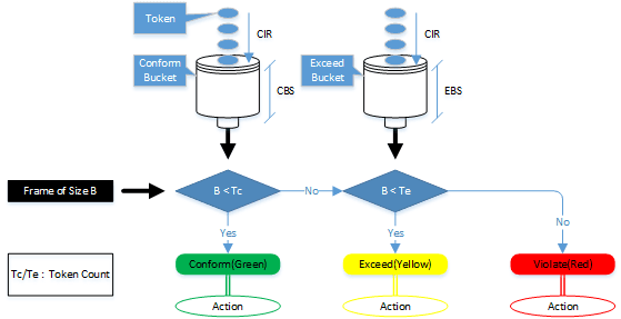
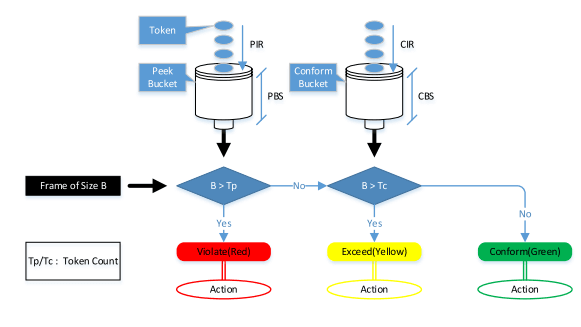
3.7.3 Setting the metering actions (policing/remarking)
The actions for bandwidth classes classified by metering types are specified using the “police” command (policy map class mode or group policer mode).
The following actions can be defined for each bandwidth class on this L2 switch.
Specifying bandwidth class actions
| Bandwidth class | Forward | Discard | Remarking |
|---|---|---|---|
| Green | ✓ | - | - |
| Yellow | ✓ | ✓ | ✓ (only one of either) |
| Red | - | ✓ |
- Use the "remark-map" command for detailed remarking settings.
As with pre-marking, up to five DSCP values can be remarked, including the value recommended by RFC (refer to appendix table 1: "Standard PHB (RFC recommended value)" and four others.
Also, when remarking, the transmission queue will be reassigned based on the changed value and the transmission queue ID conversion table that corresponds to the trust mode. - If metering is not done, all frames that have been classified into traffic classes will be handled as the green bandwidth class.
3.8 Storing in the transmission queue
Frames are stored in the transmission queue that is finally determined through a series of QoS processing.
In order to resolve jam status on the transmission queue, this L2 switch offers a system to select and discard frames.
- Tail drop
This L2 switch uses the tail drop method as a measure to resolve overflow in the transmission queue.When the threshold values shown below for the bandwidth class that is classified by metering has been exceeded, the frame in question will be discarded.
Bandwidth class Tail drop threshold value (%) Green + Yellow 100% Red 60%
- Tail drop always functions if flow control is disabled.
It is not possible to change the threshold value. - The extent of the jam can be checked using the "show mls qos queue-counters" command.
- The number of packets discarded by tail drop can be checked using the show interface or show frame-counter command.
3.9 Scheduling
Scheduling is used to determine what rules are used to send out the frames that are stored in the transmission queue.
Appropriate control of the scheduling along with the system to control congestion will help ensure QoS.(Inappropriate scheduling will result in degradation of QoS.)
This L2 switch support two types of scheduling for the transmission queue, the strict priority system (SP) and the weighted round-robin (WRR) system.
SP and WRR can also be integrated in the interface and used together.(When doing so, SP will be given priority during processing.)
- Strict priority system (SP)
The data with the highest priority in the queue will be transmitted first.
When a frame is stored in a high-priority queue, it can never be transmitted from a lower-priority queue.
- Weighted round-robin system (WRR)
A weight is set for each queue, and frames are transmitted based on the ratio. A weight of 1–32 can be set.
Frames can also be transmitted from a lower-priority queue, within a specified percentage.
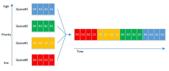
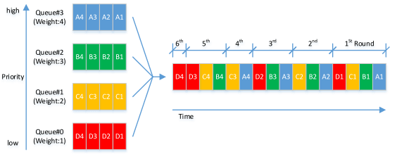
The transmission queue settings are made for the entire system, not for each interface.
Use the "mls qos wrr-weight" command to set the weight.
The default setting (when QoS is enabled) and the scheduling setting is "SP" for all queues.
3.10 Shaping
If a frame is forwarded from a broadband network to a narrowband network at the same transmission speed when connecting to a network with different bandwidth, the frame cannot be forwarded, which may result in insufficient bandwidth.
Shaping is a function that monitors the frame transmission speed, and restricts the forwarding rate to a specific amount by temporarily buffering frames with a speed that exceeds the limit, and then transmitting them.
Shaping on this L2 switch is realized by using a single token bucket.
- Single token bucket
- Shaping can be set per port or per queue, using the respective commands shown below.
Shaping target Command for settings Per port traffic-shape Per transmission queue traffic-shape queue - The upper limit of the transmission rate (CIR) and the burst size (BC) are specified.
- The upper limit of the transmission rate (CIR) can be specified from 18–1,000,000 kbps.
- The burst size (BC) can be specified from 4–16,000 KB. This is specified in 4 KB units.
- When shaping both per queue and per port, the per-port shaping will be applied after the per-queue shaping.
- The default setting (when QoS is enabled) and the shaping setting is "disable" for all ports and queues.
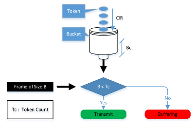
Appendix table 1: Standard PHB (RFC recommended value)
Standard PHB (RFC recommended value)
| PHB | DSCP value | RFC | |
|---|---|---|---|
| Default | 0 | RFC2474 | |
| CS (Class Selector) | CS0 | 0 | RFC2474 |
| CS1 | 8 | ||
| CS2 | 16 | ||
| CS3 | 24 | ||
| CS4 | 32 | ||
| CS5 | 40 | ||
| CS6 | 48 | ||
| CS7 | 56 | ||
| AF (Assured Forwarding) | AF11 | 10 | RFC2597 |
| AF12 | 12 | ||
| AF13 | 14 | ||
| AF21 | 18 | ||
| AF22 | 20 | ||
| AF23 | 22 | ||
| AF31 | 26 | ||
| AF32 | 28 | ||
| AF33 | 30 | ||
| AF41 | 34 | ||
| AF42 | 36 | ||
| AF43 | 38 | ||
| EF (Expedited Forwarding) | 46 | RFC2598 | |
4 Related Commands
The related commands are shown below.
For details on the commands, refer to the Command Reference.
List of related commands
| Operations | Operating commands |
|---|---|
| Enable/disable QoS | mls qos enable |
| Set default CoS | mls qos cos |
| Change trust mode | mls qos trust |
| Generate policy map for ingress frames | policy-map |
| Apply policy map for ingress frames | service-policy input |
| Show status of QoS function setting | show mls qos |
| Show QoS information for LAN/SFP port | show mls qos interface |
| Show egress queue usage ratio | show mls qos queue-counters |
| Show policy map information | show policy-map |
| Set CoS - transmission queue ID conversion table | mls qos cos-queue |
| Set DSCP - transmission queue ID conversion table | mls qos dscp-queue |
| Port priority settings | mls qos port-priority-queue |
| Priority settings for frames transmitted from switch | mls qos queue sent-from-cpu |
| Generate class map (traffic category conditions) | class-map |
| Associate class map | class |
| Set traffic classification conditions (access-group) | match access-group |
| Set traffic classification conditions (CoS) | match cos |
| Set traffic classification conditions (TOS precedence) | match ip-precedence |
| Set traffic classification conditions (DSCP) | match ip-dscp |
| Set traffic classification conditions (Ethernet Type) | match ethertype |
| Set traffic classification conditions (VLAN ID) | match vlan |
| Set traffic classification conditions (VLAN ID range) | match vlan-range |
| Show class map information | show class-map |
| Generate standard IPv4 access list | ip-access-list |
| Generate extended IPv4 access list | ip-access-list |
| Generate IPv6 access list | ip-access-list |
| Generate MAC access list | mac-access-list |
| Show QoS access list | show qos-access-list |
| Set pre-marking (CoS) | set cos |
| Set pre-marking (TOS precedence) | set ip-precedence |
| Set pre-marking (DSCP) | set ip-dscp |
| Set individual policer/group policer (single rate) | police single-rate |
| Set individual policer/group policer (twin rate) | police twin-rate |
| Set individual policer/group policer remarking | remark-map |
| Create group policer | aggregate-police |
| Show group policer | show aggregate-police |
| Apply group policer | police-aggregate |
| Show metering counter | show mls qos metering-counters |
| Clear metering counter | clear mls qos metering-counters |
| Set egress queue (CoS-Queue) | set cos-queue |
| Set egress queue (DSCP-Queue) | set ip-dscp-queue |
| Set egress queue scheduling | mls qos wrr-weight |
| Set traffic shaping (individual port) | traffic-shape rate |
| Set traffic shaping (by queue) | traffic-shape queue rate |
5 Examples of Command Execution
5.1 Priority control (SP) using DSCP values
This example allocates the transmission queue based on the DSCP value of the frame, for priority control (SP).
When the DSCP = 56, 46, 8, 0 frame is received, large frames for DSCP values from LAN port #3 will be processed with priority.
- DSCP priority control (SP): setting example
- Prioritizing the input frame is done as follows.
- DSCP = 56 frame is set at priority level 7
- DSCP = 46 frame is set at priority level 5
- DSCP = 8 frame is set at priority level 1
- DSCP = 0 frame is set at priority level 0

- This sets the trust mode for the reception ports (LAN ports #1 and #2) on which QoS is enabled.
L2SW(config)# mls qos enable … (Enables QoS.)
L2SW(config)# interface ge1 … (Set LAN port #1.)
L2SW(config-if)# mls qos trust dscp … (Set the trust mode to DSCP.)
L2SW(config-if)# exit
L2SW(config)# interface ge2 … (Set LAN port #2.
L2SW(config-if)# mls qos trust dscp … (Set the trust mode to DSCP.)
L2SW(config-if)# exit
- This sets the DSCP - transmission queue ID conversion table.
As the transmission queue ID corresponding to DSCP value = 46, 56 is the default, there is no need to make this setting, but it is listed for purposes of clarity.
L2SW(config)# mls qos dscp-queue 56 7 … (Assign egress queue #7 to DSCP value "56.")
L2SW(config)# mls qos dscp-queue 46 5 … (Assign egress queue #5 to DSCP value "46.")
L2SW(config)# mls qos dscp-queue 8 1 … (Assign egress queue #1 to DSCP value "8.")
L2SW(config)# mls qos dscp-queue 0 0 … (Assign egress queue #0 to DSCP value "0.")
- This sets the scheduling method per transmission queue.
As this is the default, there is no need to make this setting, but it is listed for purposes of clarity.
L2SW(config)# no mls qos wrr-weight 7 … (Set egress queues #7 to the SP method.)
L2SW(config)# no mls qos wrr-weight 5 … (Set egress queues #5 to the SP method.)
L2SW(config)# no mls qos wrr-weight 1 … (Set egress queues #1 to the SP method.)
L2SW(config)# no mls qos wrr-weight 0 … (Set egress queues #0 to the SP method.)
5.2 Priority control (SP+WRR) using an access list
This example classifies traffic by using the source IP address, and sets the priority control (WRR).
- Priority control (SP+WRR): setting example
- Classification conditions and priority setting for input frames
- The packet from 192.168.10.2 is classified as traffic A, and is set with a priority level of 7 during packet transmission
- The packet from 192.168.20.2 is classified as traffic B, and is set with a priority level of 6 during packet transmission
- The packet from 192.168.30.2 is classified as traffic C, and is set with a priority level of 5 during packet transmission
- The packet from 192.168.40.2 is classified as traffic D, and is set with a priority level of 4 during packet transmission
- The packet from 192.168.50.2 is classified as traffic E, and is set with a priority level of 3 during packet transmission
- The packet from 192.168.60.2 is classified as traffic F, and is set with a priority level of 2 during packet transmission
- The packet from 192.168.70.2 is classified as traffic G, and is set with a priority level of 1 during packet transmission
- The packet from 192.168.80.2 is classified as traffic H, and is set with a priority level of 0 during packet transmission
- Scheduling method
These are the integrated SP and WRR settings to make.
Queue ID Method Weight (%) 7 SP - 6 SP - 5 SP - 4 WRR 8 (40.0%) 3 WRR 6 (30.0%) 2 WRR 3 (15.0%) 1 WRR 2 (10.0%) 0 WRR 1 (5.0%)
- This enables QoS, defines the access lists for traffic A–H, and defines the traffic classes that will be set in the LAN ports.
L2SW(config)# mls qos enable … (Enables QoS.)
L2SW(config)# ip-access-list 1 permit 192.168.10.2 0.0.0.0 … (Traffic-A)
L2SW(config)# class-map cmap-A
L2SW(config-cmap)# match access-group 1
L2SW(config-cmap)# exit
L2SW(config)# ip-access-list 2 permit 192.168.20.2 0.0.0.0 … (Traffic-B)
L2SW(config)# class-map cmap-B
L2SW(config-cmap)# match access-group 2
L2SW(config-cmap)# exit
L2SW(config)# ip-access-list 3 permit 192.168.30.2 0.0.0.0 … (Traffic-C)
L2SW(config)# class-map cmap-C
L2SW(config-cmap)# match access-group 3
L2SW(config-cmap)# exit
L2SW(config)# ip-access-list 4 permit 192.168.40.2 0.0.0.0 … (Traffic-D)
L2SW(config)# class-map cmap-D
L2SW(config-cmap)# match access-group 4
L2SW(config-cmap)# exit
L2SW(config)# ip-access-list 5 permit 192.168.50.2 0.0.0.0 … (Traffic-E)
L2SW(config)# class-map cmap-E
L2SW(config-cmap)# match access-group 5
L2SW(config-cmap)# exit
L2SW(config)# ip-access-list 6 permit 192.168.60.2 0.0.0.0 … (Traffic-F)
L2SW(config)# class-map cmap-F
L2SW(config-cmap)# match access-group 6
L2SW(config-cmap)# exit
L2SW(config)# ip-access-list 7 permit 192.168.70.2 0.0.0.0 … (Traffic-G)
L2SW(config)# class-map cmap-G
L2SW(config-cmap)# match access-group 7
L2SW(config-cmap)# exit
L2SW(config)# ip-access-list 8 permit 192.168.80.2 0.0.0.0 … (Traffic-H)
L2SW(config)# class-map cmap-H
L2SW(config-cmap)# match access-group 8
L2SW(config-cmap)# exit
- This reverts the CoS - transmission queue ID conversion table to the default setting.
L2SW(config)# no mls qos cos-queue 0
L2SW(config)# no mls qos cos-queue 1
L2SW(config)# no mls qos cos-queue 2
L2SW(config)# no mls qos cos-queue 3
L2SW(config)# no mls qos cos-queue 4
L2SW(config)# no mls qos cos-queue 5
L2SW(config)# no mls qos cos-queue 6
L2SW(config)# no mls qos cos-queue 7
- This generates and applies the policy to LAN port #1 (ge1).
This sets a transmission queue with CoS value 7 to traffic-A, and a transmission queue with CoS value 6 to traffic-B.
L2SW(config)# policy-map pmap1
L2SW(config-pmap)# class cmap-A
L2SW(config-pmap-c)# set cos-queue 7 … (Set to local precedence 7 for Traffic-A.)
L2SW(config-pmap-c)# exit
L2SW(config-pmap)# class cmap-B
L2SW(config-pmap-c)# set cos-queue 6 … (Set to local precedence 6 for Traffic-B.)
L2SW(config-pmap-c)# exit
L2SW(config-pmap)# exit
L2SW(config)# interface ge1 … (Set LAN port #1.)
L2SW(config-if)# service-policy input pmap1 … (Set the policy map for received frames.)
L2SW(config-if)# exit
- This generates and applies the policy to LAN port #2 (ge2).
This sets a transmission queue with CoS value 5 to traffic-C, and a transmission queue with CoS value 4 to traffic-D.
L2SW(config)# policy-map pmap2
L2SW(config-pmap)# class cmap-C
L2SW(config-pmap-c)# set cos-queue 5 … (Set to local precedence 5 for Traffic-C.)
L2SW(config-pmap-c)# exit
L2SW(config-pmap)# class cmap-D
L2SW(config-pmap-c)# set cos-queue 4 … (Set to local precedence 4 for Traffic-D.)
L2SW(config-pmap-c)# exit
L2SW(config-pmap)# exit
L2SW(config)# interface ge2 … (Set LAN port #2.)
L2SW(config-if)# service-policy input pmap2 … (Set the policy map for received frames.)
L2SW(config-if)# exit
- This generates and applies the policy to LAN port #3 (ge3).
This sets a transmission queue with CoS value 3 to traffic-E, and a transmission queue with CoS value 0 to traffic-F.
L2SW(config)# policy-map pmap3
L2SW(config-pmap)# class cmap-E
L2SW(config-pmap-c)# set cos-queue 3 … (Set to local precedence 3 for Traffic-E.)
L2SW(config-pmap-c)# exit
L2SW(config-pmap)# class cmap-F
L2SW(config-pmap-c)# set cos-queue 0 … (Set to local precedence 0 for Traffic-F.)
L2SW(config-pmap-c)# exit
L2SW(config-pmap)# exit
L2SW(config)# interface ge3 … (Set LAN port #3.)
L2SW(config-if)# service-policy input pmap3 … (Set the policy map for received frames.)
L2SW(config-if)# exit
- This generates and applies the policy to LAN port #4 (ge4).
This sets a transmission queue with CoS value 2 to traffic-E, and a transmission queue with CoS value 1 to traffic-F.
L2SW(config)# policy-map pmap4
L2SW(config-pmap)# class cmap-G
L2SW(config-pmap-c)# set cos-queue 2 … (Set to local precedence 1 for Traffic-G.)
L2SW(config-pmap-c)# exit
L2SW(config-pmap)# class cmap-H
L2SW(config-pmap-c)# set cos-queue 1 … (Set to local precedence 1 for Traffic-H.)
L2SW(config-pmap-c)# exit
L2SW(config-pmap)# exit
L2SW(config)# interface ge4 … (Set LAN port #4.)
L2SW(config-if)# service-policy input pmap4 … (Set the policy map for received frames.)
L2SW(config-if)# exit
- This sets the scheduling method for the transmission queue.
As this queue IDs 5, 6, and 7 are the defaults, there is no need to make this setting, but it is listed for purposes of clarity.
L2SW(config)# mls qos wrr-weight 0 1 … (Egress queue 0: WRR method, weight 1.)
L2SW(config)# mls qos wrr-weight 1 2 … (Egress queue 1: WRR method, weight 2.)
L2SW(config)# mls qos wrr-weight 2 3 … (Egress queue 2: WRR method, weight 3.)
L2SW(config)# mls qos wrr-weight 3 6 … (Egress queue 3: WRR method, weight 6.)
L2SW(config)# mls qos wrr-weight 4 8 … (Egress queue 4: WRR method, weight 8.)
L2SW(config)# no mls qos wrr-weight 5 … (Egress queue 5: SP method.)
L2SW(config)# no mls qos wrr-weight 6 … (Egress queue 6: SP method.)
L2SW(config)# no mls qos wrr-weight 7 … (Egress queue 7: SP method.)
5.3 Priority control when using port priority trust mode
This determines the transmission queue, based on the port priority specified for each reception port.
- Priority control using port priority: setting example
- Priority settings for each reception port
- Set the priority of LAN port #1 (ge1) to “6”.
- Set the priority of LAN port #2 (ge2) to “4”.
- Set the priority of LAN port #3 (ge3) to “2”.

- Enable the QoS and set the trust mode for the reception ports (LAN ports #1, #2 and #3) on which QoS is enabled.
L2SW(config)#mls qos enable … (Enables QoS.)
L2SW(config)#interface ge1 … (Set LAN port #1.)
L2SW(config-if)#mls qos trust port-priority … (Set the trust mode to Port priority)
L2SW(config-if)#mls qos port-priority-queue 6 … (Set port priority order 6)
L2SW(config-if)#exit
L2SW(config)#interface ge2 … (Set LAN port #2.)
L2SW(config-if)#mls qos trust port-priority … (Set the trust mode to Port priority)
L2SW(config-if)#mls qos port-priority-queue 4 … (Set port priority order 4)
L2SW(config-if)#exit
L2SW(config)#interface ge3 … (Set LAN port #3.)
L2SW(config-if)#mls qos trust port-priority … (Set the trust mode to Port priority)
L2SW(config-if)#mls qos port-priority-queue 2 … (Set port priority order 2)
L2SW(config-if)#exit
5.4 Bandwidth control using an access list (twin rate individual policer)
This example set bandwidth control by using the source IP address. Use a twin rate policer and individual policer for metering.
- Bandwidth control: setting example
- Classification conditions and bandwidth limits for input frames
- The packet from 192.168.10.2 is classified as traffic A, and the reception rate (CIR) is limited to 25 Mbps.
- The packet from 192.168.20.2 is classified as traffic B, and the reception rate (CIR) is limited to 15 Mbps.
- The packet from 192.168.30.2 is classified as traffic C, and the reception rate (CIR) is limited to 10 Mbps.
- This enables QoS, defines the access lists for traffic A–C, and defines the traffic classes that will be set in the LAN ports.
L2SW(config)#mls qos enable … (Enables QoS.)
L2SW(config)#ip-access-list 1 permit 192.168.10.2 0.0.0.0 … (Traffic-A)
L2SW(config)#class-map cmap-A
L2SW(config-cmap)#match access-group 1
L2SW(config-cmap)#exit
L2SW(config)#ip-access-list 2 permit 192.168.20.2 0.0.0.0 … (Traffic-B)
L2SW(config)#class-map cmap-B
L2SW(config-cmap)#match access-group 2
L2SW(config-cmap)#exit
L2SW(config)#ip-access-list 3 permit 192.168.30.2 0.0.0.0 … (Traffic-C)
L2SW(config)#class-map cmap-C
L2SW(config-cmap)#match access-group 3
L2SW(config-cmap)#exit
- This generates and applies the policy to LAN port #1 (ge1).
Metering for traffic A through traffic C is set individually.
The twin rate policer can discard the yellow and red bandwidths to retain (guarantee) the green bandwidths.
L2SW(config)#policy-map pmap1
L2SW(config-pmap)#class cmap-A … (Set metering on Traffic-A.)
L2SW(config-pmap-c)#police twin-rate 25000 25000 156 11 yellow-action drop red-action drop
L2SW(config-pmap-c)#exit
L2SW(config-pmap)#class cmap-B … (Set metering on Traffic-B.)
L2SW(config-pmap-c)#police twin-rate 15000 15000 93 11 yellow-action drop red-action drop
L2SW(config-pmap-c)#exit
L2SW(config-pmap)#class cmap-C … (Set metering on Traffic-C.)
L2SW(config-pmap-c)#police twin-rate 10000 10000 62 11 yellow-action drop red-action drop
L2SW(config-pmap-c)#exit
L2SW(config-pmap)#exit
L2SW(config)#interface ge1… (Set LAN port #1.)
L2SW(config-if)#service-policy input pmap1 … (Set the policy map for received frames.)
L2SW(config-if)#exit
- The metering setting values are shown below.
- Traffic-A: CIR (25,000 kbps), CBS (156 KB), EBS (11 KB)
- Traffic-B: CIR (15,000 kbps), CBS (93 KB), EBS (11 KB)
- Traffic-C: CIR (10,000 kbps), CBS (62 KB), EBS (11 KB)
The following calculation is used to find the CBS, with a round-trip time of 0.05 sec.
CBS = CIR (bps) ÷ 8 (bit) × 0.05 (second)
- The metering setting values are shown below.
5.5 Bandwidth control using an access list (single rate group policer)
This example sets bandwidth control by using the source IP address. Use a single rate policer and group policer for metering.
- Bandwidth control: setting example
- Classification conditions and bandwidth limits for input frames
- The packet from 192.168.10.2 is classified as traffic A.
- The packet from 192.168.20.2 is classified as traffic B.
- The packet from 192.168.30.2 is classified as traffic C.
- The reception rates for traffic A, B and C are limited to 25Mbps.
- The yellow bandwidth class is remarked as DSCP = 0, and is transmitted at low priority.
- This enables QoS, defines the access lists for traffic A–C, and defines the traffic classes that will be set in the LAN ports.
L2SW(config)#mls qos enable … (Enables QoS.)
L2SW(config)#ip-access-list 1 permit 192.168.10.2 0.0.0.0 … (Traffic-A)
L2SW(config)#class-map cmap-A
L2SW(config-cmap)#match access-group 1
L2SW(config-cmap)#exit
L2SW(config)#ip-access-list 2 permit 192.168.20.2 0.0.0.0 … (Traffic-B)
L2SW(config)#class-map cmap-B
L2SW(config-cmap)#match access-group 2
L2SW(config-cmap)#exit
L2SW(config)#ip-access-list 3 permit 192.168.30.2 0.0.0.0 … (Traffic-C)
L2SW(config)#class-map cmap-C
L2SW(config-cmap)#match access-group 3
L2SW(config-cmap)#exit
- This sets the DSCP - transmission queue ID conversion table.
The transmission queue with the lowest priority is assigned for the DSCP value (0) used in remarking the yellow bandwidth.
L2SW(config)#mls qos dscp-queue 0 0
- A group policer is created.
L2SW(config)#aggregate-police agp1 … (Generate aggregate policer)
L2SW(config-agg-policer)#police single-rate 25000 156 11 yellow-action remark red-action drop
L2SW(config-agg-policer)#remark-map yellow ip-dscp 0
L2SW(config-agg-policer)#exit
- The metering setting values for the group policer are shown below.
- Metering type: single rate policer
- Yellow is remarked as “DSCP value = 0”
- CIR (25,000 kbps), CBS (156 KB), EBS (11 KB)
The following calculation is used to find the CBS, with a round-trip time of 0.05 sec.
CBS = CIR (bps) ÷ 8 (bit) × 0.05 (second)
- The metering setting values for the group policer are shown below.
- This generates and applies the policy to LAN port #1 (ge1).
Set the metering for traffic A through traffic C that has been grouped together (group policer).
L2SW(config)#policy-map pmap1
L2SW(config-pmap)#class cmap-A … (Set metering on Traffic-A.)
L2SW(config-pmap-c)#police-aggregate agp1
L2SW(config-pmap-c)#exit
L2SW(config-pmap)#class cmap-B … (Set metering on Traffic-B.
L2SW(config-pmap-c)#police-aggregate agp1
L2SW(config-pmap-c)#exit
L2SW(config-pmap)#class cmap-C … (Set metering on Traffic-C.)
L2SW(config-pmap-c)#police-aggregate agp1
L2SW(config-pmap-c)#exit
L2SW(config-pmap)#exit
L2SW(config)#interface ge1… (Set LAN port #1.)
L2SW(config-if)#service-policy input pmap1 … (Set the policy map for received frames.)
L2SW(config-if)#exit
6 Points of Caution
- The functions listed below can be used from Rev.2.01.04 upwards.
- Port priority trust mode
- Priority specification for frames transmitted from switch
- IPv6 access list
- Group policers, twin rate policers
- Shaping (per transmission queue)
- Starting with Revision .2.01.07, QoS cannot be enabled when flow control is enabled in the system.
7 Related Documentation
Flow control
1 Function Overview
A switching hub initially stores received frames in memory and then performs relay processing.
When many frames are sent at the same time and relay processing cannot keep up (a congested state), exceeding the available memory capacity for storage, the frames to be relayed are discarded.
This L2 switch includes the following two functions to help mitigate congestion.
- When ports are operating at full duplex: IEEE 802.3x flow control can be enabled.
- When ports are operating at half duplex: the back pressure function will always be enabled.
2 Definition of Terms Used
- Bit time
On a 10BASE network, the speed is 10Mbps, with 1 bit time = 100 nsec.
Similarly, on a 100BASE network, the bit time is 10 nsec; and on a 1000BASE network, the bit time is 1 nsec.
- Jam signals
In half-duplex communications, where data cannot be transmitted and received at the same time, there is a possibility of data collision.
The transmitting device monitors the possibility of data collision during transmission. When possible data collision is detected, the device stops transmitting and sends a jam signal. After the jam signal is sent, the device waits for a random interval before resuming transmission.
Although undefined in IEEE, jam signals that use a 32-digit alternating "1" and "0" bit sequence (such as
"10101010101010101010101010101010") are often used.- Tail drop
If the transmission queue discard threshold value is exceeded, then the corresponding frame is discarded.
For details, refer to the technical reference for QoS.
3 Function Details
3.1 IEEE 802.3x flow control
For full duplex communication, the MAC control protocol with IEEE802.3x option can be used.
The MAC control frame in the diagram below is used for flow control.
MAC control frame
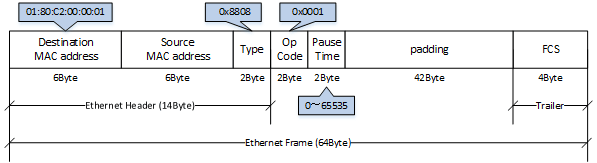
The following flow control operations are performed, based on the restriction start threshold and the restriction cancel threshold.
Flow control: processing flow
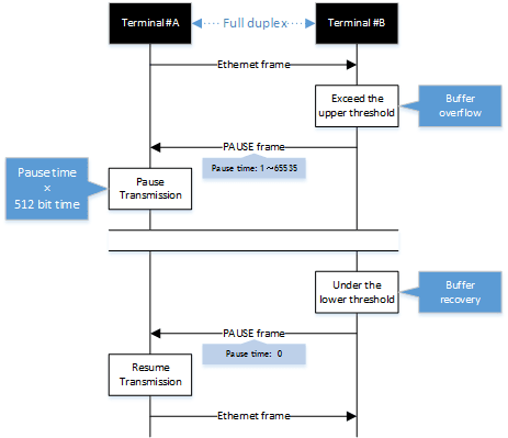
This L2 switch can be used for either transmitting or receiving MAC control frames. The operations for each are shown below.
- MAC control frame transmission processing
- Frames are stored in the receive buffer. When the number of frames exceeds the restriction start threshold, a PAUSE frame with a relay time of 65535 is sent.
- When the overflow in the receive buffer is resolved, and the number of frames falls below the restriction cancel threshold, a PAUSE frame with a relay time of 0 is sent.
- MAC control frame reception processing
- When a PAUSE frame with a relay time of 1–65535 is received, the transmission processing will be stopped if the corresponding bit time has elapsed, or if the a PAUSE frame with a relay time of 0 has been received.
Use the "flowcontrol enable" command to enable or disable the flow control (when transmitting/receiving MAC control frames).
This setting can be made for each transmitting/receiving LAN/SFP port, and is set to "disable" by factory default.
In order to enable flow control for an individual port, flow control must be enabled for the system.
When flow control is enabled for the system, the tail drop function is disabled.
If the QoS function is enabled, flow control cannot be enabled.
The restriction start threshold and restriction cancel threshold are set using the "flowcontrol threshold" command.
The default restriction start threshold value is 80%, and the default restriction cancel threshold is 60%. The threshold values are common throughout the system.
3.2 Back pressure
This L2 switch sends a jam signal whenever the receiving buffer of a LAN port is about to overflow.
With this, the sender waits for a random amount of time as per the CSMA/CD, and then sends the frames.
When the LAN port is operating at half duplex: the back pressure function will always be enabled.
Back pressure processing flow
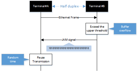
4 Related Commands
The related commands are shown below.
For details on the commands, refer to the Command Reference.
List of related commands
| Operations | Operating commands |
|---|---|
| Set (system) flow control (IEEE 802.3x PAUSE send/receive) | flowcontrol enable |
| Set (interface) flow control (IEEE 802.3x PAUSE send/receive) | flowcontrol |
| Set flow control threshold (start/cancel control) | flowcontrol threshold |
| Show flow control operating status | show flowcontrol |
5 Examples of Command Execution
- In this example, the restriction start threshold is set to 75%, the restriction cancel threshold is set to 50%, and the flow control for LAN port #1 is enabled.
After the function is enabled, this checks on the operating status of the flow control.
L2SW(config)# flowcontrol enable
L2SW(config)# flowcontrol threshold pause 75 cancel 50
L2SW(config)# interface ge1
L2SW(config-if)# flowcontrol enable
L2SW(config-if)# end
L2SW# show flowcontrol ge1
Port    FlowControl    Pause Threshold Cancel Threshold    RxPause TxPause
-----   -----------    --------------- ----------------    ------- -------
ge1     Enable                      75               50          0      64
6 Points of Caution
- If updated from an older version (Rev. 2.01.05 or earlier), flow control is disabled.
Flow control is enabled by executing the "flowcontrol enable" command in the global configuration mode.
However, because it disables the tail drop function, the command that causes HOL blocking may occur. - The following command settings will fail if an older version (Rev. 2.01.05 or earlier) is restored. This results in disabling flow control.
- Flow control enable (global configuration)
- Flow control both/auto (interface mode)
- Starting with Revision .2.01.07, flow control cannot be enabled in the system when QoS is enabled.
7 Related Documentation
Storm control
1 Function Overview
This L2 switch provides a storm control function as a countermeasure against L2 loops and DoS attacks.
Broadcasts, multicasts, and unicast (dlf) frames that are addressed to an unknown host are monitored for each LAN/SFP port, and frames that exceed a preset threshold value are discarded.
This prevents such frames from taking up bandwidth on the LAN/SFP port.
Using this along with the proprietary loop detection and storm control functions enhances the precision of loop detection (avoiding such frames in the first place).
2 Definition of Terms Used
- Broadcast storm/multicast storm
This means a situation where frames addressed for broadcast or multicast are continuously forwarded.
In this situation, the switch floods all ports except for the reception port with the broadcast or multicast.
When this is received by another switch, all ports except for the reception port are flooded in the same way.
When this continues, it can lead to the following symptoms.
- Bandwidth is taken up by the broadcast storm/multicast storm
- The switch's CPU load increases, making normal operations difficult
- Devices connected to the switch become unable to communicate
- Unicast stream
This means a situation where frames addressed to an unknown unicast destination (dlf: Destination Lookup Failure) are continuously forwarded.
When the MAC address of the receiving device has not been registered in the ARP table, all ports on the switch except for the reception port are flooded.
This leads to the same symptoms occurring as with a broadcast storm or multicast storm.
3 Function Details
The operating specifications for storm control are shown below.
- The storm control function can be enabled for LAN/SFP ports.
The setting is disabled for all ports by default.
- Storm control on this L2 switch can be specified as a tolerance percentage for the bandwidth of the LAN/SFP ports that receive broadcast frames, multicast frames, and frames addressed to an unknown unicast destination.
(Control can be made in two decimal points. Specifying 100% is the same as disabling the storm function.)
The bandwidth tolerance is common for all frames, and the user can select the applicable frames.
The settings are made using the "storm-control" command.
- The following SYSLOG will be outputted at the time that storm control is enabled or disabled.
- When enabled: [ STORM]:inf: storm-control ENABLE (port:ge1, type:B M U, level:50. 0%)
- When disabled: [ STORM]:inf: storm-control DISABLE (port:ge1)
- When frames are received that exceeds the permitted bandwidth, the excessive frames are discarded.
- Use the "show storm-control" command to check the storm control information set for the LAN/SFP port.
4 Related Commands
The related commands are shown below.
For details on the commands, refer to the Command Reference.
List of related commands
| Operations | Operating commands |
|---|---|
| Set storm control | storm-control |
| Show storm control reception upper limit | show storm-control |
5 Examples of Command Execution
In this example, the receivable L2 broadcast packets for LAN port 1 of the L2 switch are restricted to a port bandwidth of 30%.
Storm control command setting: example
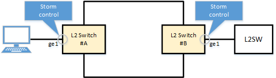
L2SW(config)# interface ge1
L2SW(config-if)# storm-control broadcast level 30 … (Set the threshold value to 30% for broadcast storm control.)
L2SW(config-if)# end
L2SW#
L2SW# show storm-control
Port    BcastLevel    McastLevel    UcastLevel
ge1       30.00%       100.00%       100.00%
ge2      100.00%       100.00%       100.00%
ge3      100.00%       100.00%       100.00%
ge4      100.00%       100.00%       100.00%
ge5      100.00%       100.00%       100.00%
ge6      100.00%       100.00%       100.00%
ge7      100.00%       100.00%       100.00%
ge8      100.00%       100.00%       100.00%
ge9      100.00%       100.00%       100.00%
6 Points of Caution
None
7 Related Documentation
- SWP1 Series Technical Data (Basic Functions)
- Other information
- SWP1 Series Technical Data (Basic Functions)
- Other information
- About the licenses
About the licenses
Open-source software used in this product
- For information about the license provisions, visit the Yamaha Pro Audio website:
- SWP1 Series Technical Data (Basic Functions)
- Other information
- Google Analytics