SWP1 Series Technical Data
Firmware revision: Rev.2.01.09
Thank you for your purchase of the Yamaha SWP1 series.
Please read this manual carefully, correctly installing the unit and making the proper settings before use.
Make sure to observe the warnings and cautions listed in this manual, in order to use the unit correctly and safely.


Firmware Updates
For stable operations of this L2 switch, we recommend that you apply the latest updates, which include new functionality and bug fixes.
Please confirm your system version when applying updates.
- Use the "show version" command to confirm the system version.
Web GUI Function
The latest firmware for this L2 switch includes the following settings and functions:
- Detailed settings
- VLAN
- MAC address table
- IGMP snooping
- QoS
- EEE
- Management
- Unit settings
- Time settings
- Access management
- Management password
- Maintenance
- Command execution (for details on the commands, refer to the Command Reference)
- Firmware update
- CONFIG file management
- SYSLOG management
- Restart and initialization
- Unit settings
Support Service Center
- Yamaha Pro Audio global website:
http://www.yamahaproaudio.com/ - Yamaha Downloads
http://download.yamaha.com/
- SWP1 Series Technical Data (GUI)
- Overall
- Introduction
Introduction
1. What you can do using the Web GUI
The web GUI lets you perform basic settings and management of the Yamaha switch (this unit). The web GUI contains the following screens for you to make settings and perform management.
- Dashboard
- LAN MAP
- Detailed settings
- Management
- CONFIG
- TECHINFO
2. Operating environment
Here we explain the environment that is required in order to use the web GUI.
Recommended web browser
We recommend the following web browser for use with the web GUI.
- Windows
- Microsoft Internet Explorer 11
- Mac
- Apple Safari 7 or later
NOTE
Do not use the "Back" or "Forward" buttons of the web browser.
In some cases, the display layout of a page may become disordered. If this occurs, please access that page once again.
Memo
The web GUI uses UTF-8 character encoding.
JavaScript settings
The web GUI uses JavaScript. If your web browser is set to disable JavaScript, you might not be able to use the web GUI itself.
In advance, please enable JavaScript as described in the following procedure.
Settings for Internet Explorer 11 (Windows version)
- On the menu bar of Internet Explorer, choose "Tools."
* If the menu bar is not visible, press the "Alt" key of the keyboard to make it appear.
- In the menu that appears, choose "Internet options."
- Select the "Security" tab.
- Verify that "Internet" (the globe symbol) is shown, and press the "Default level" button.
If you can't press this button, "Default level" is already selected. Proceed to step 5.
Alternatively, you can use the following method.
- Press the "Custom level" button to open the "Security Settings - Internet Zone" dialog box.
- Under "Scripting," choose "Enable" for each of the two items "Scripting of Java applets" and "Allow Programmatic clipboard access."
- Click "OK." The warning "Do you want to change the settings of this zone?" is shown. Click "Yes."You will return to "Internet Options." Click the "OK" button.
- You will return to "Internet Options." Click the "OK" button.
Settings for Safari 7 (Mac version)
- On the menu, select "Safari" and choose "Preferences."
- In the window that appears, choose "Security."
- Add a check mark for "Allow plug-ins" and "Enable JavaScript."
- Close the "Security" window.
3. User access rights
Users who log in to the web GUI are divided into two types: general users and administrative users. These are referred to as "access levels." The differences between the access levels are described below.
- For general users
- Can view the settings of the unit. Cannot change the settings.
- For administrative users
- Can view and change the settings of the unit. The user can also obtain CONFIG and TECHNIFO.
4. Note when using together with command input
Settings for this unit can be made not only via the web GUI but also from the command console screen by directly entering commands. Command input allows a broader range of settings than when using the web GUI, and also lets you make settings for functions that are not supported in the web GUI. If you use both command input and the web GUI to make settings, be aware that the commands that you input may be overwritten, or the settings may be cleared.
Memo
The command console screen contains the following items.
Management -> "Maintenance" -> "Command execution"
For details on commands, refer to "Command reference."
- SWP1 Series Technical Data (GUI)
- Overall
- Logging in and logging out
Logging in and logging out
1. Login method
Here we explain how to log in to the web GUI of this unit.
Log in as general user
- Start your web browser, and access "http://(the IP address you assigned to the unit)/".
- A dialog box asking you to enter a user name and password appears.
- Enter "guest" as the user name, and enter the login password.
* If you log in as a general user, you will be able to view the unit's settings and operating status. You will not be able to make settings for this unit.
Log in as administrative user
- Start your web browser, and access "http://(the IP address you assigned to the unit)/".
- A dialog box asking you to enter a user name and password appears.
- Enter "administrator" as the user name, and enter the specified password when moving to the specially privileged EXEC mode.
* If you log in as an administrative user, you will be able to perform all web GUI operations. You can not only view the unit's settings and operating status, but also make settings for the unit.
Log in again as another user
- In the upper right of the screen, press the "Log out" button to log out.
- Close the web browser. Then open it again and log in again.
About general users and administrative users
- General users
- The user name is "guest".
- As the password, use the login password (the text string specified by the "password" command).
In the factory-set state, this password is unset.
- Administrative users
- The user name is "administrator".
- As the password, use the password specified when moving to the specially privileged EXEC mode (the text string specified by the "enable password" command).
In the factory-set state, this password is unset.
About passwords
- You must enter the password as single-byte characters. Double-byte characters may not be used. Uppercase and lowercase characters are distinguished.
- If an incorrect user name or password is stored in your web browser, the login authentication dialog box might not appear. Close and reopen the web browser, and access this unit once again. If the browser is storing auto-login user information, delete it.
- Take care not to forget the password that you assigned. If you have forgotten the password, ask the administrator who set up this unit for the correct password.
2. Logout method
To log out of the web GUI for this device, press the "Log out" button in the upper right of the GUI screen. After you log out, be sure to close the web browser.
- SWP1 Series Technical Data (GUI)
- Overall
- About each screen
About each screen
1. Dashboard
It shows the various system information of this device in visual form. You can check and monitor the following status.
- Interface information
- System information
- Resource information ( CPU Utilization / MemoryUtilization )
- SYSLOG
2. LAN MAP
In this page you can view, manage, and make settings for the Yamaha network devices managed by the LAN interface, and any equipment under its management.
The LAN map is shown only if this unit is operating as a controller.
3. Detailed settings
In this page you can make detailed network-related settings for this unit. The following items are provided.
- VLAN
- Create VLAN
- Tag VLAN
- Link aggregation
- Load balance
- MAC address table
- IGMP snooping
- QoS
- EEE
- E-mail notification
4. Management
In this page you can make settings for this unit, and perform maintenance. The following items are provided.
- Unit settings
- Access management
- Maintenance
- Command execution
- Update firmware
- CONFIG management
- SYSLOG management
- Restart and initialization
- GUI display language
5. CONFIG
The results of running the "show running-config" command (a setting of this unit) can be viewed in a web browser or acquired as a text file.
- Viewing CONFIG
- In the "CONFIG" menu, press the "Show in browser" button. The execution result of the "show running-config" command is shown in a sub-window.
- To close, press the web browser's close button.
- Obtaining CONFIG as a text file
- In the "CONFIG" menu, press the "Obtain as text file" button to start the download automatically.
- The name of the acquired file is "config_YYYYMMDDhhmmss.txt".
YYYY ... A.D. ( 4 Digit ) MM ... Month ( 2 Digit ) DD ... Day ( 2 Digit ) hh ... Hours ( 2 Digit ) mm ... Minutes ( 2 Digit ) ss ... Seconds ( 2 Digit )
6. TECHINFO
The "show tech-support" command lets you view status information for all of this unit's functions.
In the "TECHINFO" menu, the results of running the "show tech-support" command can be viewed in a web browser or acquired as a text file.
- Viewing TECHNIFO
- In the "TECHINFO" menu, press the "Show in browser" button. The execution result of the "show tech-support" command is shown.
- To close, press the web browser's close button.
- Obtaining TECHNIFO as a text file
- In the "TECHINFO" menu, press the "Obtain as text file" button to start the download automatically.
- The name of the acquired file is "technifo_YYYYMMDDhhmmss.txt".
YYYY ... A.D. ( 4 Digit ) MM ... Month ( 2 Digit ) DD ... Day ( 2 Digit ) hh ... Hours ( 2 Digit ) mm ... Minutes ( 2 Digit ) ss ... Seconds ( 2 Digit )
Notes
- It may take some time to obtain TECHNIFO.
- This unit may undergo loading while the information is being acquired.
- SWP1 Series Technical Data (GUI)
- Dashboard
- SWP1 Series Technical Data (GUI)
- Dashboard
- About the dashboard
About the dashboard
Using the dashboard
- What is the dashboard?
- The page that provides visualization and monitoring of various system information and status information is called the "dashboard."
- What is a gadget?
- Each window shown in the dashboard is called a "gadget."
- Information for each gadget is automatically updated at regular intervals.
Using the gadgets
The following gadgets can be used.
- System information
- Resource information
- Interface information
- SYSLOG
Each gadget has the following functions.
- Separate the gadget screen:
- A "Separate" button (
) is shown in the upper right of each gadget.
- If you press the "Separate" button, that gadget alone is shown in a different window.
- At this time, the corresponding gadget in the dashboard is indicated as "In separate window."
- If a gadget is separated, the following occurs.
- The "Separate" button is no longer shown for the separated gadget.
- When you update the dashboard display, all separated gadgets return to the dashboard and are shown.
- When you close the dashboard, all separated gadgets are also closed.
- Separated gadgets can also be displayed by specifying a URL directly in the browser.
Example) System information gadget: http://192.168.100.1/dashboard/system.html
- A "Separate" button (
- Minimize gadget:
- When you press the minimize icon (
- When you press it again, the icon returns to its original downward orientation (
- When you press the minimize icon (
- Auto-update gadget:
- All gadgets are automatically updated at regular intervals.
- The update interval differs depending on the gadget.
 ) is shown in the upper right of each gadget.
 ) in the upper left of each gadget, the icon turns sideways (
 ) and the gadget display is minimized.
- SWP1 Series Technical Data (GUI)
- Dashboard
- About each gadget
About each gadget
Interface information
This shows the link status of the ports.
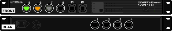
- The "Port" icon display lets you check the link status of the ports.
- When you move the mouse cursor over the "Port" icon, detailed port information is shown.
- The "Port" icon is shown as follows depending on the link status.
For a LAN port
| Icon | Explanation |
|---|---|
 | Link up (port speed 1000BASE-T) |
 | Link up (port speed 100BASE-TX) |
 | Link up (port speed 10BASE-T) |
 | Link down |
 | Error occurrence (Loop detection, Shutdown by BPDU guard) |
For an SFP port
| Icon | Explanation |
|---|---|
| Link up (full duplex) | |
| Link down | |
| Error occurrence (Loop detection, Shutdown by BPDU guard) |
System information
The following information is displayed.
- Device name:
- Display the device name of the switch.
- Firmware revision:
- Firmware revision
- Serial number:
- Serial number of the device
- This is also shown by a label on the rear of the chassis.
- MAC address:
- MAC address of the device
- This is also shown by a label on the rear of the chassis.
- Currently-running settings file:
- The currently used CONFIG file is shown.
- Depending on CONFIG switch 1, either config0 (if ON) or config1 (if OFF) is loaded when the system starts up.
- System time:
- Current device date and time
- If the date and time are incorrect, set the date and time either in the Web GUI's "Management" -> "Device settings" page, or by using the clock set command or the ntpdate command.
- Startup time:
- System startup date and time
- Startup reason:
- Reason for startup
- Start from power-off state, reload command, revision up, etc.
Resource information
This page shows the CPU usage and memory usage.
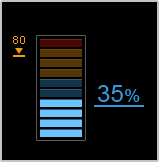
- The current values and peak values of CPU usage and memory usage are shown.
- The number at the right of the meter is the current usage, and the number at the left is the peak value.
- When you click "Clear peak values," the previous peak values will be cleared.
- Peak values are also cleared when you restart the device.
- When you move the mouse cursor to each meter, the peak value and the date and time at which the peak value was recorded are shown.
SYSLOG
This shows the most recent SYSLOG.
- The most recent log is at the top.
- In the select menu you can change the number of lines that are displayed (default: 10 lines).
- SWP1 Series Technical Data (GUI)
- Detailed settings
Interface
1. Summary
In this page you can edit the physical interface settings.
2. Top page
This is the top page of the interface settings.
Interface list
- For each interface, this shows the current operating status and settings of the physical interface.
- The items in the table are explained below.
- Check box
- Add a check mark when you want to make settings for multiple interfaces or to initialize settings.
- Port
- This shows the interface name.
- Link
- This shows the interface's link status.
- In the case of other than a LAN port, the port type is shown in parentheses.
- Speed and communication mode
- This shows the currently-operating speed and communication mode.
- In the case of an automatic setting, (auto) is shown at the end of the status indication.
- EEE
- This shows the operating status of the EEE function.
- Description
- This displays the explanatory text that is specified for the interface.
- Check box
- Press the "Setting" button to access a page where you can change the settings of the selected interface.
- If you press the "Set all" button, the settings can be changed for all interfaces whose check box contains a check mark.
- You cannot make a multiple selection that includes ports of differing types.
- The default values are reflected in the settings page of the physical interface.
- When you press the "Return to defaults" button, the settings will be initialized for all interfaces whose check box contains a check mark.
- The default values for each setting are as follows.
- Operation: Enable the interface
- Description: Unspecified
- Speed/communication mode: Automatic
- EEE function: Disabled (Don't use power-conservation Ethernet function)
- The default values for each setting are as follows.
3. Physical interface settings page
In this page you can edit the physical interface settings.
Enter the settings, and then press the "OK" button.
If there are no mistakes in the input content of the confirmation screen, press the "OK" button.
Physical interface settings
- Port
- This shows the name of the interface that you're setting.
- Operation
- Choose the interface's operation from the following.
- Enable the interface
- Disable the interface
- Choose the interface's operation from the following.
- Description
- Sets the description text for the interface.
- You can enter single-byte alphanumeric characters except for the ? character.
- Up to 80 characters can be entered.
- Speed and communication mode
- Choose the interface's speed and communication method from the following.
- For a LAN port
- Automatic
- 1 Gbps / full duplex
- 100 Mbps / full duplex
- 100 Mbps / half duplex
- 10 Mbps / full duplex
- 10 Mbps / half duplex
- For an SFP port
- Automatic
- 1 Gbps / full duplex
- For a LAN port
- Choose the interface's speed and communication method from the following.
- EEE function
- The EEE function can be set only for LAN ports.
- Choose the EEE function's operation from the following.
- Disabled (Don't use power-conservation Ethernet function)
- Enabled (Use power-conservation Ethernet function)
- SWP1 Series Technical Data (GUI)
- Detailed settings
- Link aggregation
Load balance
1. Summary
In this page, you can change the settings for the load balance function.
2. Top page
This is the top page for load balance.
Static logical interface
- Information for the defined static logical interface is shown.
- Press the "Setting" button to access a page where you can change the settings of the selected logical interface.
LACP logical interface
- Information for the defined LACP logical interface is shown.
- Press the "Setting" button to access a page where you can change the settings of the selected logical interface.
3. Load balance function settings page
In this page, you can change the settings for the load balance function.
Enter the settings, and then press the "OK" button.
If there are no mistakes in the input content of the confirmation screen, press the "OK" button.
Load balance function settings
- Logical interface
- The logical interface names that will be set are shown.
- Load balance function
Select the load balance function rules from the following items.
- Source and destination IP address (traffic will be distributed based on the source and destination IP addresses)
- Source and destination MAC address (traffic will be distributed based on the source and destination MAC addresses)
- Source and destination TCP/UDP port number (traffic will be distributed based on the source and destination TCP/UDP port numbers)
- Source IP address (traffic will be distributed based on the source IP address)
- Source MAC address (traffic will be distributed based on the source MAC address)
- Source TCP/UDP port number (traffic will be distributed based on the source TCP/UDP port number)
- Destination IP address (traffic will be distributed based on the destination IP address)
- Destination MAC address (traffic will be distributed based on the destination MAC address)
- Destination TCP/UDP port number (traffic will be distributed based on the destination TCP/UDP port number)
Create VLAN
1. Summary
In this page you can create or delete VLANs, and change the IP address.
2. Top page
This is the top page for creating a VLAN.
VLAN list
- Information for the defined VLANs is displayed
- A maximum of 20 items can be displayed for one page. Press
- You can press the sort switch to sort by each item.
- Press the "New" button to access a page where you can create a new VLAN
- Press the "Setting" button to access a page where you can change the settings of the selected VLAN
- If you press the "Delete" button, all VLANs whose check box has a check mark will be deleted
- The following VLAN cannot be deleted
- Default VLAN (VLAN ID = 1)
- Private VLAN
- VLAN used for link aggregation, an access list, an MST instance, and maintenance functions
- The following VLAN cannot be deleted
- Up to 256 VLANs can be created including the default VLAN (VLAN ID = 1).
3. VLAN settings page
In this page you can create a new VLAN or edit the settings of an already-defined VLAN.
Enter the settings, and then press the "OK" button.
If there are no mistakes in the input content of the confirmation screen, press the "OK" button.
VLAN settings
- VLAN ID
- To create a new VLAN, enter the desired VLAN ID within the valid range (2-4094)
- The smallest ID of the unregistered VLAN IDs is entered as the default value
- If an already-registered VLAN ID is entered, it is handled as a change in settings
- When changing the settings, it is not possible to change the VLAN ID
- To create a new VLAN, enter the desired VLAN ID within the valid range (2-4094)
- Name
- Specify the name of the VLAN using up to 32 single-byte alphanumeric characters and symbols.
- The default VLAN (VLAN ID = 1) cannot be renamed
- A space and "?" cannot be used in the name of the VLAN.
- Specify the name of the VLAN using up to 32 single-byte alphanumeric characters and symbols.
- Frame transmission
Select frame forwarding from the following items.
- Enable frame transmission
- Disable frame transmission
- Frame forwarding cannot be disabled for the default VLAN (VLAN ID = 1)
- IP address
Select the IP address from the following items. Only a VLAN for which frame forwarding is valid can be specified for this item.
Only one IP address can be specified for all VLAN interfaces. Note that when you make settings, the existing IP address is deleted.
- Not set
- Obtain automatically using DHCP
- Specify a fixed IP address
- Enter the IP address and subnet mask
Tagged VLAN
1. Summary
In this page you can make settings for tagged VLANs.
2. Top page
This is the top page for tagged VLANs.
Tagged VLAN settings
- The various settings for tagged VLANs are shown for each LAN/SFP port.
- "Frame types that can be received" is displayed according to the operating mode and the VLAN settings. (This item cannot be set in the settings page.)
- Press the "Setting" button to access a page where you can change the settings for the tagged VLAN of the selected port.
- If you press the "Specify all" button, the settings can be changed for all LAN/SFP ports whose check box contains a check mark.
- If you press the "Return to defaults" button, the settings will be initialized for all LAN/SFP ports whose check box contains a check mark.
- The default settings for a tagged VLAN are as follows.
- Operating mode: Access
- Assigned VLAN: Default VLAN (VLAN ID = 1)
- The default settings for a tagged VLAN are as follows.
- Settings for the LAN/SFP port assigned to a private VLAN cannot be changed.
- Settings for the LAN/SPF port used for link aggregation cannot be changed.
- If the operation mode is "Trunk," both the native VLAN and the trunk VLAN are shown as assigned VLANs.
3. Tagged VLAN settings page
In this page you can make various settings related to tagged VLANs.
Enter the settings, and then press the "OK" button.
If there are no mistakes in the input content of the confirmation screen, press the "OK" button.
Tagged VLAN settings
- Port
- The LAN/SFP port for which settings are made is shown.
- Operating mode
- Access
- The corresponding port is specified as the access (untagged) port.
- Trunk
- The corresponding port is specified as the trunk (tagged) port.
- Access
- Associated VLAN
The content of the settings differs depending on the operating mode.
For an access port:
- Access VLAN
- From the list, select the access port's assigned VLAN.
- However, the following cannot be selected as an access VLAN.
- Private VLAN
- VLAN for which frame forwarding is disabled
For a trunk port:
- Native VLAN
- From the list, select the assignment-destination VLAN (native VLAN) for untagged frames received by the trunk port.
- Note that the following cannot be selected as a native VLAN.
- VLAN selected as trunk VLAN
- Private VLAN
- VLAN for which frame forwarding is disabled
- Setting the native VLAN of the uplink port or downlink port to “none” will make the following functions unavailable.
- L2MS (LAN map display)
- Spanning tree
- Link aggregation
- Proprietary loop detection
- Trunk VLAN
- Specify the assignment-destination VLAN (trunk VLAN) for tagged frames received by the trunk port.
- When you press the "Select" button, a list of the selectable VLAN IDs appears in a separate window.
- Note that the following cannot be selected as trunk VLAN.
- VLAN selected as native VLAN
- Private VLAN
- VLAN for which frame forwarding is disabled
- Place a check mark in the check box of the VLAN ID that you want to specify, and press the "Confirm" button.
- Access VLAN
- Ingress filter
Select the ingress filter from the following items. This item is shown only if the operating mode is "Trunk".
- Enabled (receive only if the VLAN ID of the incoming frame is the same as the associated VLAN)
- Disabled (receive all frames)
- SWP1 Series Technical Data (GUI)
- Detailed settings
- MAC address table
MAC address table
1. Summary
In this page you can edit the settings of the MAC address table function.
2. Top page
This is the top page for the MAC address table.
Basic settings for MAC address learning function
- The current settings for the MAC address learning function are shown
- When you press the "Setting" button, a page where you can change the MAC address learning function settings will appear
Static MAC address table settings
- The static MAC address table is shown as a list
- A maximum of 20 items can be displayed for one page. Press
- You can press the sort switch to sort by each item.
- If you press the "New" button, a page appears in which you can create a new static MAC address entry.
- If you press the "Setting" button, a page appears in which you can edit the settings of the selected static MAC address entry.
- If you press the "Delete" button, all static MAC address entries whose check box has a check mark will be deleted
- Up to 512 static MAC address entries can be created from the Web GUI.
3. MAC address learning function basic settings page
In this page you can make settings for the MAC address learning function.
Enter the settings, and then press the "OK" button.
If there are no mistakes in the input content of the confirmation screen, press the "OK" button.
Basic settings for MAC address learning function
- MAC address learning function
Select the MAC address learning function from the following items.
- Use MAC address learning function
- Don't use MAC address learning function
- Aging time for dynamic entries
- Specify a setting in the range of 10 seconds to 634 seconds. The default value is 300 seconds
4. Static MAC address table settings page
In this page you can make static MAC address settings.
Enter the settings, and then press the "OK" button.
If there are no mistakes in the input content of the confirmation screen, press the "OK" button.
Static MAC address settings
- Kind
Choose from the following items as the type of MAC address to be registered in the static MAC address table.
- Register a unicast MAC address
- Register a multicast MAC address
- Destination MAC address
- To input directly
- In the input area in the upper left of the frame, enter the MAC address in the format hhhh.hhhh.hhhh
- To convert IP multicast group addresses to multicast MAC addresses
- Conversion is possible only when registering a multicast MAC address
- Enter the address in the input area in the lower part of the frame, and then press the "Convert" button
- If conversion is successful, the MAC address is shown in the input area in the upper left of the frame
- If conversion fails, an error message is displayed
- Frame processing
From the following items, select the processing for frames sent to the destination MAC address.
- Forward frames that are being sent to the destination MAC address
- Discard frames that are being sent to the destination MAC address
- If a multi-cast MAC address is registered, "Forward" is the only frame processing that can be specified
- Destination VLAN ID
- Select the forwarding-destination VLAN ID from those that are registered in the VLAN database
- Forwarding destination interface
- If you press the "Select" button, the interfaces assigned to the forwarding-destination VLAN ID are shown as a list
Place a check mark in the check box of the interface that you want to use as the forwarding-destination interface, and press the "Confirm" button
- If registering a unicast MAC address, you can specify one interface
- If registering a multicast MAC address, you can specify multiple interfaces
- If you press the "Select" button, the interfaces assigned to the forwarding-destination VLAN ID are shown as a list
Routing
1. Summary
In this page you can make routing settings.
2. Top page
This is the top page for routing settings.
Routing table
- This shows details of the routing table.
- The items in the table are explained below.
- Check box
- Place a check in this box to delete static route information.
- Enabled routes
- A route that is used for actual communication is indicated by
- A route that is not used for actual communication is indicated by
- A route that is used for actual communication is indicated by
- Type
- One of the following is shown as the type of route information.
- static
- connected
- One of the following is shown as the type of route information.
- Destination
- This shows the destination network address of the route information.
- If the destination is the default gateway, this indicates default.
- Gateway
- This shows the gateway of the route information.
- If set to discard packets, this indicates Null.
- Priority order
- This shows the administrative distance of the route information.
- Check box
- If you press the "New" button, a page appears in which you can make new settings for static route information.
- If you press the "Setting" button, a page appears in which you can edit the settings of the selected static route information.
- If you press the "Delete" button, all static route information whose check box has a check mark will be deleted.
- Static route information entries show a check box and a "Setting" button.
- Up to 64 static route information entries can be created.
 Enabled.
 Disabled.
4. Static route information settings page
In this page you can make static route information settings.
Enter the settings, and then press the "OK" button.
If there are no mistakes in the input content of the confirmation screen, press the "OK" button.
Set static route information
- Destination network
- When making new settings
- Select the destination network from the following
- Specify the network address
- Enter the destination network address
- Default gateway
- Specify the network address
- Select the destination network from the following
- When editing the settings
- This shows the destination network address
- When making new settings
- Gateway
- Select the gateway from the following
- Specify IP address
- Enter the gateway's IP address
- Discard without forwarding packets
- Specify IP address
- Select the gateway from the following
- Priority order
- Enter the priority order
- The input range is 1–255
DNS client
1. Summary
In this page you can make DNS client settings.
2. Top page
This is the top page for DNS client settings.
DNS client settings
- This page shows the DNS client settings.
- The items in the table are explained below.
- DNS client function
- The setting indicates whether the DNS client function is enabled or disabled.
- DNS server address
- This shows the setting for the DNS server address that is queried to resolve a name.
- Default domain
- This shows the default domain setting.
- Search domain
- This shows the search domain setting.
- DNS client function
- Press the "Setting" button to access a page where you can make DNS client settings.
3. DNS client settings page
In this page you can make DNS client settings.
Enter the settings, and then press the "OK" button.
If there are no mistakes in the input content of the confirmation screen, press the "OK" button.
DNS client settings
- DNS client function
- Choose the operation of the DNS client function from the following.
- Enable
- Disable
- Choose the operation of the DNS client function from the following.
- DNS server address
- This specifies the DNS server address.
- The server address can be specified either as an IPv4 address or an IPv6 address.
- You can specify up to three server addresses.
- Default domain
- This specifies the default domain.
- Up to 256 characters can be entered.
- Search domain
- This specifies the search domain.
- Up to 256 characters can be entered.
- You can specify up to six search domains.
- SWP1 Series Technical Data (GUI)
- Detailed settings
- IGMP snooping
IGMP snooping
1. Summary
In this page you can edit the settings of the IGMP snooping function.
2. Top page
This is the top page for IGMP snooping.
IGMP snooping function settings
- IGMP snooping function settings are shown for each VLAN ID that is defined
- A maximum of 20 items can be displayed for one page. Press
- When you press the "Setting" button, a page where you can change the IGMP snooping function settings for the selected VLAN ID will appear
- If you press the "Specify all" button, the settings can be changed for all VLAN IDs whose check box contains a check mark
- If you press the "Return to defaults" button, the settings will be initialized for all VLAN IDs whose check box contains a check mark
- Default settings for the IGMP snooping function are as follows
- IGMP snooping function: Enabled
- IGMP version: IGMPv3
- IGMP querier: Disabled
- IGMP query transmission interval: 125 seconds
- TTL check: Enabled
- Default settings for the IGMP snooping function are as follows
3. IGMP snooping function settings page
In this page you can make various settings for the IGMP snooping function.
Enter the settings, and then press the "OK" button.
If there are no mistakes in the input content of the confirmation screen, press the "OK" button.
IGMP snooping function settings
- VLAN ID
- The VLAN ID for which settings are being made is shown
- IGMP snooping function
- Enabled ( Control transmission of IP multicast packets )
- Enables the IGMP snooping function
By monitoring (snooping) the IGMP messages that are exchanged between the receiving equipment and the multicast router, multicast packet flooding can be controlled, limiting the network bandwidth that is used.
- Enables the IGMP snooping function
- Disabled ( Flood IP multicast packets )
- Disables the IGMP snooping function
Multicast packets are always forwarded to all ports in the same VLAN.
- Disables the IGMP snooping function
- IGMP version
Select the IGMP version from the following items.
- IGMPv3
- IGMPv2
- IGMP querier
- Enabled ( Periodically transmit IGMP queries )
- IGMP query transmission function is enabled. The transmission interval can be specified in the range of 20 seconds to 18000 seconds
- Disabled ( Don't transmit IGMP queries )
- IGMP query transmission function is disabled
- TTL check
Select the TTL check from the following items.
- Enabled ( IGMP packets other than TTL=1 are discarded )
- Disabled ( IGMP packets other than TTL=1 are corrected to TTL=1 and transmitted )
QoS
1. Summary
In this page you can edit the settings of the QoS (Quality of Service) function.
You can enable/disable the QoS function, and change the trust mode.
2. Top page
This is the top page for QoS.
QoS function basic settings
- The current setting is shown as to whether the QoS function is used
- Press the "Setting" button to access a page where you can change the settings
- In order to enable the QoS function, you must enter the CLI's global configuration mode, and then disable flow control.
QoS function settings
- The trust mode setting used by the QoS function is shown for each LAN/SFP port
- Press the "Setting" button to access a page where you can change the settings of the selected LAN/SFP port
- If you press the "Specify all" button, the settings can be changed for all LAN/SFP ports whose check box contains a check mark
- If you press the "Return to defaults" button, the settings will be initialized for all LAN/SFP ports whose check box contains a check mark
- The default trunk mode setting for all ports is "CoS"
- If the settings do not use the QoS function, QoS function settings cannot be made
3. QoS function basic settings page
In this page you can specify whether the QoS function is used.
Enter the settings, and then press the "OK" button.
If there are no mistakes in the input content of the confirmation screen, press the "OK" button.
Be aware that if the settings do not use the QoS function, all QoS-related settings will be cleared.
QoS function basic settings
- QoS function
- Don't use QoS function
- The QoS function will be disabled. At this time, all QoS settings will be cleared.
- Use QoS function
- The QoS function will be enabled. QoS-related settings and commands can be executed.
4. QoS function settings page
This page is for setting the "Trust mode", which means whether the transmission queue is determined based on the packet's CoS value, the DSCP value, or the priority set for the port.
Enter the settings, and then press the "OK" button.
If there are no mistakes in the input content of the confirmation screen, press the "OK" button.
QoS function settings
- Port
The LAN/SFP port for which settings are made is shown
- Trust mode
- Use CoS value to determine transmission queue
- The packet's CoS value and the "CoS - Transmission queue ID conversion table" are used to determine the transmission queue
- If the received packet is an untagged packet, the default CoS value is applied
- For details on checking and changing the default CoS value and the "CoS - Transmission queue ID conversion table," refer to the command reference
- Use DSCP value to determine transmission queue
- The packet's DSCP value and the "DSCP - Transmission queue ID conversion table" are used to determine the transmission queue
- For details on checking and changing the "DSCP - Transmission queue ID conversion table," refer to the command reference
- Use the priority set for the port to determine transmission queue
- Determine the transmission queue ID according to port priority
- Select the transmission queue to assign as port priority, within a range of 0–7
The larger the number, the higher the priority. The default value is “2”.
- This setting can be changed only when the trust mode is set to “port priority”.
- If a policy map is applied to the LAN/SFP port, you cannot change the trust mode setting.
- Use CoS value to determine transmission queue
- SWP1 Series Technical Data (GUI)
- Detailed settings
- Mail notification
Mail notification
1. Summary
In this page you can configure e-mail-related settings. When e-mail notifications are set, an e-mail will automatically be sent to a certain e-mail address when specified conditions are met.
To begin, on the “List of registered e-mail servers”, click “New” to register a destination e-mail server. After registering the address, click “New” on the “List of e-mail notification settings” to configure the e-mail notifications.
E-mail notifications can only be configured from the Web GUI. The configuration details for e-mail notifications will not be shown in the CONFIG file. Further, operations performed on the CONFIG file (such as “erase startup-config”) will not change the e-mail notification settings.
2. Top page
This is the top page for e-mail notifications.
List of registered e-mail servers
- Information for the currently registered e-mail servers (SMTP servers) is displayed.
- Settings can be added from the “New” button above the list.
- To change the settings, click on the “Settings” button on the right side of the table. The page where you can change the settings will be displayed.
- To delete the settings, select the settings to delete and click the “Delete” button above the list. A confirmation dialog box will appear. Click “Delete” to delete the settings.
- Up to 10 e-mail servers can be registered.
List of e-mail notification settings
- The current settings for e-mail notifications that have been configured will be displayed.
- Settings can be added from the “New” button above the list.
- To change the settings, click on the “Settings” button on the right side of the table. The page where you can change the settings will be displayed.
- To delete the settings, select the settings to delete and click the “Delete” button above the list. A confirmation dialog box will appear. Click “Delete” to delete the settings.
3. E-mail server settings page
This page is for configuring the destination e-mail server (SMTP server). After confirming the items that were set, press the "OK" button. If there are no mistakes in the input content confirmation screen, press the "OK" button.
List of registered e-mail servers
- ID number
- This is the e-mail server settings ID number. This number is assigned automatically.
- Account ID name
- This sets the e-mail server account ID name. It may be convenient to use a name that is easy to identify.
- Up to 64 half-width characters can be used.
- This can be skipped.
- SMTP server address
- Input the IP address or the domain name of the SMTP server address to use for sending e-mail.
- Up to 64 half-width characters can be used.
- SMTP server port number
- Input the SMTP server port number.
- When a check mark is added to “Submission port (port 587)”, the submission port (port 587) will be set.
Note: This function does not support SMTP authentication.
4. E-mail notification settings page
In this page you can configure e-mail notification settings. The source and destination addresses for e-mail notifications can be set. After confirming the items that were set, press the "OK" button. If there are no mistakes in the input content confirmation screen, press the "OK" button.
Caution: If the e-mail server settings have not been configured, you will not be able to configure the e-mail notifications.
E-mail notification settings
- ID number
- This is the e-mail notification settings ID number. This number is assigned automatically.
- Source (From)
- Sets the source e-mail address for sending e-mail.
- SMTP server:
- Select the SMTP server to use for sending e-mail.
- E-mail address:
- Input the source e-mail address for sending e-mail.
- Up to 64 half-width characters can be used. Note that symbols besides “_” (underscore), “-” (hyphen), “.” period, and “@” (at sign) cannot be used.
- Sets the source e-mail address for sending e-mail.
- Destination (To)
- Input the destination e-mail address for sending e-mail.
- Up to four addresses can be registered, and e-mails will be sent to all addresses registered.
- Up to 64 half-width characters can be used. Note that symbols besides “_” (underscore), “-” (hyphen), “.” period, and “@” (at sign) cannot be used.
- Subject
- Sets the subject for the e-mails to be sent.
- Up to 128 half-width characters can be used.
- When “Use the default subject” is selected, the default subject is used.
- Notification message
- Sets the notification message (content).
- E-mail transmission delay time
- When a notification event occurs, this sets how long the system waits before sending the e-mail.
- If another notification event occurs during the delay period, these notifications are lumped together and sent along in the same e-mail.
- SWP1 Series Technical Data (GUI)
- Management
- Unit settings
Unit settings
1. Summary
You can make settings related to date and time of the unit.
2. Top page
This is the top page for this unit's settings. The current date and time, time zone setting, and date and time synchronization setting are shown.
Time zone setting
The time zone setting is shown.
- Press the "Setting" button to access a page where you can change the settings.
Current date and time setting
The current date and time specified for this unit are shown.
- Press the "Setting" button to access a page where you can change the settings.
Date and time synchronization setting
The NTP server that is queried at the specified time and date synchronization interval is shown.
- Press the "Next" button to access a page where you can synchronize the time.
- Press the "Setting" button to access a page where you can change the settings.
3. Time zone setting page
In this page you can set the time zone.
When you have entered the settings, press the "OK" button. If there are no mistakes in the input content confirmation screen, press the "OK" button.
Time zone setting
- Time zone
- Select the time zone from the following.
- UTC
- JST
- Difference from GMT ( -12:00 to +13:00 )
- Select the time zone from the following.
4. Current date and time setting page
In this page you can set the current date and time.
When you have entered the settings, press the "OK" button. If there are no mistakes in the input content confirmation screen, press the "OK" button.
Current date and time setting
- Current time
- In the "year/month/date" box, enter the date in YYYY/MM/DD format.
- When you move the focus to the box, a calender is displayed. You can select a date to enter that date in the box.
- You can also enter this manually.
- In the "hours:minutes:seconds" box, enter the time in hh:mm:ss format.
- When you move the focus to the box, a calender is displayed. You can select a date to enter that date in the box.
- You can also enter this manually.
- In the "year/month/date" box, enter the date in YYYY/MM/DD format.
5. Date and time synchronization page
In this page you can synchronize the time with an NTP server.
When you press the "Execute" button, the time is synchronized with the NTP server that is specified as the query destination.
6. Date and time synchronization setting page
In this page you can make settings for synchronization with an NTP server.
When you have entered the settings, press the "OK" button. If there are no mistakes in the input content confirmation screen, press the "OK" button.
Date and time synchronization setting
- Date and time synchronization interval
- Specifies the interval at which time is synchronized with the NTP server.
- You can choose from the following as the synchronization interval.
- Unused
- 1 hour - 24 hours
- The default value is 1 hour
- NTP server to query
- Enter the host name or IP address of the NTP server that will perform synchronization.
- The default value is ntp.nict.jp.
- SWP1 Series Technical Data (GUI)
- Management
- Access management
- SWP1 Series Technical Data (GUI)
- Management
- Access management
- Administrator password settings
Administrator password settings
1. Summary
This function is for setting the password for administrative users.
2. Top page
This is the top page for administrator password settings. Indicates whether an administrator password has been set.
Administrator password settings
Shows whether the administrator password is currently set.
- The password will not be displayed.
- Press the "Setting" button to access a page where you can change the settings.
3. Administrator password setting page
On this page you can set the passwords for administrative users.
When you have entered the settings, press the "OK" button. If there are no mistakes in the input content confirmation screen, press the "Confirm Settings" button.
Administrator password settings
- New password
- Enter the administrator password that you will newly set.
- If a password has already been set, it will be displayed using black dots (●).
- You can check the password strength that is shown while you are entering your password.
- The password strength is indicated in four levels from "weak" to "strongest" based on the following conditions.
- Whether the password is too short
- Whether alphabetic uppercase and lowercase characters are included
- Whether number and symbols are included
- The following passwords can not be set.
- Passwords that contain the "|", ">” or "?” symbols
- Passwords that do not start with a letter or number
- Passwords containing only one character (such as “8”)
- Passwords containing only two characters (with one of them being a space), such as “8 ”
- New password (confirm)
- To confirm the password that you entered in the "New password" field, enter the password once again.
- Password encryption
- Select whether the password should be encrypted when saved.
- If you save the password without encryption, it will be displayed as-is in the CONFIG settings.
- You cannot change the encryption setting alone for passwords on which encryption is already set.
- SWP1 Series Technical Data (GUI)
- Management
- Access management
- Various server settings
Various server settings
1. Summary
In this page you can make various server settings.
2. Top page
This is the top page for making various server settings.
The current settings for the following servers are shown.
- HTTP server
- TELNET server
- TFTP server
Access via the Web GUI
- The HTTP server settings are shown.
- The items in the table are explained below.
- Use HTTP server
- Indicates whether the HTTP server is used.
- If the HTTP server is used, the port number is shown.
- Interfaces that can access the HTTP server
- Shows the interfaces that can access the HTTP server.
- Use HTTP server
Access using TELNET
- The TELNET server settings are shown.
- The items in the table are explained below.
- Use TELNET server
- Indicates whether the TELNET server is used.
- If the TELNET server is used, the port number is shown.
- Interfaces that can access the TELNET server
- Shows the interfaces that can access the TELNET server.
- Clients that can access the TELNET server
- Shows the clients that can access the TELNET server.
- Use TELNET server
Access using TFTP
- The TFTP server settings are shown.
- The items in the table are explained below.
- Interfaces that can access the TFTP server
- Shows the interfaces that can access the TFTP server.
- Interfaces that can access the TFTP server
3. Web GUI access page
In this page you can make settings for the HTTP server.
Enter the settings, and then press the "OK" button.
If there are no mistakes in the input content of the confirmation screen, press the "OK" button.
Access via the Web GUI
- Use HTTP server
- Select from the following to specify whether the HTTP server is used.
- Use
- Don't use
- If Use is selected, specify the port number.
- The input range for the port number is 1–65535.
- Select from the following to specify whether the HTTP server is used.
- Interfaces that can access the HTTP server
- Press the "Select" button to access the "VLAN interface list" dialog box.
- In the "VLAN interface list" dialog box, add a check mark to a port's check box and press the "Confirm" button to select an interface.
- Up to eight VLAN interfaces can be selected.
4. TELNET access page
In this page you can make settings for the TELNET server.
Enter the settings, and then press the "OK" button.
If there are no mistakes in the input content of the confirmation screen, press the "OK" button.
Access using TELNET
- Use TELNET server
- Select from the following to specify whether the TELNET server is used.
- Use
- Don't use
- If Use is selected, specify the port number.
- The input range for the port number is 1–65535.
- Select from the following to specify whether the TELNET server is used.
- Interfaces that can access the TELNET server
- The method of making settings for this item is the same as in the Web GUI access page item "Interfaces that can access the HTTP server”.
- Clients that can access the TELNET server
- Select from the following methods of limiting client access.
- Allow all
- Specify conditions
- If you choose Specify conditions, you can specify up to eight conditions.
- Specify the following as conditions.
- Operation
- Choose the operation for access restriction from the following.
- Allow
- Deny
- Choose the operation for access restriction from the following.
- Condition
- Choose the object of access restriction from the following.
- All addresses
- Specify IP address
- Choose the object of access restriction from the following.
- IP address
- If you choose Specify IP address, specify the IP address.
- You can specify the following as the IP address.
- IPv4 address
- Example: 192.168.100.1
- IPv4 network address
- Example: 192.168.100.0/24
- IPv6 address
- Example: fe80::1234:5678
- IPv6 network address
- Example: 2001:1234:5678:90ab::0/64
- IPv4 address
- Operation
- By pressing the
- By pressing the "Delete" button you can delete a settings form.
- Select from the following methods of limiting client access.
 icon you can add a settings form.
5. TFTP access page
In this page you can make settings for the TFTP server.
Enter the settings, and then press the "OK" button.
If there are no mistakes in the input content of the confirmation screen, press the "OK" button.
Access using TFTP
- Interfaces that can access the TFTP server
- The method of making settings for this item is the same as in the Web GUI access page item "Interfaces that can access the HTTP server”.
- SWP1 Series Technical Data (GUI)
- Management
- Maintenance
- Command execution
Command execution
1. Summary
In this page you can perform operations related to command execution.
2. Command execution page
In this page you can execute commands and acquire the results of command execution. After entering the command in the command entry field, press the "Execute" button to execute the command. If you press the "Clear" button, the contents of the command entry field are cleared.
Command execution
- Command input
- In the command entry field, enter the setting in console command format (abbreviated input is not accepted).
- You can enter multiple commands together by separating them with line-returns.
- Execution always starts with the specially-privileged EXEC mode (enable). Enter the mode change command each time.
- For details on commands to enter, refer to the command reference and to the information provided on the SWP1 product information page.
- The following commands cannot be entered.
- cold start
- firmware-update execute
- ping
- quit
- reload
- show history
- show tech-support
- telnet
- disable ( When in special privilege EXEC mode )
- exit ( When in special privilege EXEC mode )
- logout ( When in special privilege EXEC mode )
- Command execution result
- Displays the command execution result.
- Success ... Shown if the command executed successfully.
- Error ... Shown if the command you entered could not be executed.
- Prohibited ... Shown if a prohibited command was entered.
- Displays the command execution result.
- Command execution log
- The console log is output as the command execution record.
- The command execution log will not necessarily always show the identical result as when the console setting operation was executed.
- By pressing the "Obtain as text file" button, you can acquire the contents of the command execution log as a text file.
- The name of the acquired file is "command_YYYYMMDDhhmmss.txt".
YYYY ... A.D. ( 4 Digit ) MM ... Month ( 2 Digit ) DD ... Day ( 2 Digit ) hh ... Hours ( 2 Digit ) mm ... Minutes ( 2 Digit ) ss ... Seconds ( 2 Digit )
- SWP1 Series Technical Data (GUI)
- Management
- Maintenance
- Update the firmware
Update the firmware
1. Summary
In this page you can perform operations related to firmware update.
2. Top page
This is the top page for firmware update.
You can start the procedure for updating the firmware via the network. Various settings for updating the firmware via the network are displayed.
Current firmware revision
- The currently-used firmware revision is shown.
Update firmware from PC
- When you press the "Next" button, the procedure for updating the firmware from the PC will be started.
Update firmware via network
- When you press the "Next" button, the procedure for updating the firmware via the network will be started.
- Various settings for updating the firmware via the network are displayed.
- Press the "Setting" button to access a page where you can change the settings.
3. Update firmware from PC page
In this page you can specify the firmware file placed on the PC from which you are accessing the web GUI, and perform the firmware update.
In "Select file," select the firmware file that you want to use for the update, and press the "OK" button. If there are no mistakes in the confirmation screen, press the "Execute" button.
Note that the unit will automatically restart when the firmware has been updated successfully.
Update firmware from PC
- Specify update file
- Selects the firmware file used for the update
4. Update firmware via network page
In this page you can download a firmware file from a web server, and perform the firmware update. This function lets you easily perform the entire process of checking for the latest firmware, downloading it, and updating the firmware.
When you open the page, the revision of the firmware file on the web server is automatically checked.
If the URL of the download source is a Yamaha website, and an updatable firmware revision is found, pressing the "Execute" button will display the software license agreement. Carefully read the software license agreement, and press either the "Agree" button or "Disagree" button. Only if you press the "Agree" button, the firmware file will start being downloaded from the web server.
Note that the unit will automatically restart when the firmware has been updated successfully.
Update firmware via network
- Current firmware revision
- The revision of the currently-used firmware file is shown.
- Firmware revision available for update
- Updatable revisions of the firmware files on the web server are shown.
5. Firmware update basic settings page
In this page you can make various settings for updating the firmware via the network.
When you have entered the settings, press the "OK" button. If there are no mistakes in the input content confirmation screen, press the "OK" button.
Firmware update basic settings
- Download source URL
- This is the setting of the URL at which the firmware is located.
- Permit downward revision
- This setting permits or forbids rewriting to an older version of firmware.
- Timeout
- This setting specifies the timeout time during the process of updating the firmware via the network.
- SWP1 Series Technical Data (GUI)
- Management
- Maintenance
- CONFIG file management
CONFIG file management
1. Summary
In this page you can import and export CONFIG files.
This unit operates in accordance with its CONFIG file (settings data). A CONFIG file consists of a combination of multiple commands.
2. Top page
This is the top page for CONFIG file management.
Here you can start the process of importing a CONFIG file from the PC, or the process of exporting a CONFIG file to the PC.
Import CONFIG file
- Press the "Next" button to begin the process of importing a CONFIG file from the PC.
Export CONFIG file
- Press the "Next" button to begin the process of exporting a CONFIG file to the PC.
3. Import CONFIG file page
In this page, a CONFIG file from the PC can be copied to internal non-volatile memory, updating the CONFIG file.
When you have entered the settings, press the "OK" button. If there are no mistakes in the input content confirmation screen, press the "Execute" button.
When import has completed successfully, the unit restarts automatically.
Import CONFIG file
- Currently-used CONFIG file
- The currently used CONFIG file is shown.
- File to import
- Press the "Select a file" button to display the file selection dialog box.
4. Export CONFIG file page
In this page you can copy a CONFIG file from internal non-volatile memory to the PC.
To export the CONFIG file, press the "Execute" button.
Export CONFIG file
- Currently-used CONFIG file
- The currently used CONFIG file is shown.
- SWP1 Series Technical Data (GUI)
- Management
- Maintenance
- SYSLOG management
SYSLOG management
1. Summary
In this page you can view and edit the settings of the SYSLOG function.
The operation history of this device is output as the SYSLOG (log data) according to the settings of the SYSLOG function. In addition to recording the SYSLOG inside this device, you can also specify a destination address for output to an external host.
2. Top page
This is the top page for SYSLOG management.
The current settings for the SYSLOG function are shown.
SYSLOG settings
- The type of SYSLOG that is output and the SYSLOG transmission destination address are shown.
- Press the "Setting" button to access a page where you can change the settings.
3. SYSLOG settings page
In this page you can make settings for the SYSLOG function.
When you have entered the settings, press the "OK" button. If there are no mistakes in the input content confirmation screen, press the "OK" button.
For details on the various SYSLOG types, refer to the command reference.
SYSLOG settings
- SYSLOG type
- DEBUG
- This setting specifies whether DEBUG type SYSLOG is output.
- INFO
- This setting specifies whether INFO type SYSLOG is output.
- ERROR
- This setting specifies whether ERROR type SYSLOG is output.
- DEBUG
- SYSLOG transmission destination address
- This is the transmission destination address setting when outputting the SYSLOG to an external host.
- You can specify only one transmission destination address.
- If no transmission destination address is specified, the SYSLOG is recorded only inside the switch.
- SWP1 Series Technical Data (GUI)
- Management
- Maintenance
- Restart and initialization
Restart and initialization
1. Summary
In this page you can restart this unit and return it to the factory-set state.
2. Top page
This is the top page for restart and initialization.
Here you can start the process of restarting this unit or returning it to the factory-set state.
Restart
- When you press the "Next" button, the process of restarting this unit will begin.
Initialization
- When you press the "Next" button, the process of returning this unit to the factory-set state will begin.
3. Restart page
In this page you can restart this unit.
When you press the "Execute" button, the unit will restart.
Note that when you execute restart, the settings that were being changed will not be saved. In addition, the GUI cannot be accessed until restart has completed.
4. Initialization page
In this page you can return this unit to its factory-set state.
After you have entered the administrator password, press the "OK" button. Confirm the content to be executed, and if you want to return this unit to its factory-set state, press the "Execute" button.
Note that when the unit is returned to its factory-set state, all settings will return to their default values, including the address for accessing the GUI.
Initialization
- Administrator password
- To return the unit to its factory-set state, enter the administrator password.
- SWP1 Series Technical Data (GUI)
- Management
- Web GUI language
Web GUI language
1. Summary
Here you can specify the display language.
2. Top page
This is the top page for the web GUI display language. The contents of the display language settings are shown.
Display language setting
The display language settings are shown.
- Press the "Setting" button to access a page where you can change the settings.
3. Web GUI display language page
In this page you can make settings for the display language.
When input is complete, check the input, and if it is correct, press the "OK" button.
Display language setting
- Language
- Select the display language from the following.
- 日本語 ( Japanese )
- English ( English )
- Select the display language from the following.