SWX3220 Series Technical Reference
Firmware revision: Rev.4.02.13
Thank you for purchasing a Yamaha SWX3220 series switch.
Before using the product, be sure to read this manual carefully to ensure the product is installed and settings are configured properly.
Be sure to observe the warnings and cautions indicated in this manual and use the product correctly and safely.
Startup Guide
This guide describes the setup procedure up to the point SWX3220 series settings can start being specified.
Settings for the SWX3220 series can be specified using any of the following four methods.
- Specify settings by executing commands using the CONSOLE port.
- Specify settings by executing commands using Telnet.
- Specify settings by executing commands using SSH.
- Specify settings using a web browser.
Preparation for Specifying Settings via the CONSOLE Port
- Prepare the computer and other items needed for specifying settings.
If specifying settings via the CONSOLE port, use a USB cable or RJ-45/DB-9 console cable (YRC-RJ45).
Use a USB cable that supports data transfer via both a USB Type A connector and a mini-USB Type B (5-pin) connector to connect to the mini-USB CONSOLE port. Charge-only cables cannot be used.
Terminal software is also needed for controlling the computer serial (COM) port.
Configure communication settings for the CONSOLE terminal as follows.- Baud rate: 9600 bps (default setting is 9600 bps, which can be changed using commands)
- Data: 8 bits
- Parity: none
- Stop bit: 1 bit
- Flow control: Xon/Xoff
- Use a USB cable or an RJ-45/DB-9 console cable (YRC-RJ45) to connect a computer to the product.
- A USB serial driver must be installed before the mini-USB CONSOLE port can be used.
- For details on how to install the USB serial driver, refer to “Yamaha Network Device USB Serial Driver Installation Guide.”
The Yamaha Network Device USB Serial Driver Installation Guide and the installer can be downloaded from the following website.
- https://usa.yamaha.com/support/updates/yamaha_network_usb_serial.html
- Switch ON the unit. The unit takes approximately 60 seconds to start up.
Immediately after startup, the following is displayed on the serial console screen.
SWX3220 BootROM Ver.1.00

Starting .............................

SWX3220-16MT Rev.4.02.XX (Fri Jan  1 00:00:00 2021)
  Copyright (c) 2018-2020 Yamaha Corporation. All Rights Reserved.
- Log in to this unit.
For factory default settings, log in by entering “admin” as the default administrative username (and “admin” as the password).
After using “admin” to log in, the password must be changed to specify a new password.
Username: admin
Password: admin

SWX3220-16MT Rev.4.02.XX (Fri Jan  1 00:00:00 2021)
  Copyright (c) 2018-2020 Yamaha Corporation. All Rights Reserved.

Please change the default password for admin.
New Password:                            ... (Enter the new password.)
New Password(Confirm):                   ... (Enter the same password again.)
Saving ...
Succeeded to write configuration

SWX3220>
- After that, specify settings as appropriate for the given product operating environment.
- For details on settings via the serial console, refer to Command Reference.
Preparation for Specifying Settings via Telnet, SSH, or a Web Browser
- Prepare the computer and other items needed for specifying settings.
- Prepare an Ethernet cable for connecting to the product.
- To access the unit via Telnet or SSH, Telnet or SSH terminal software must be installed on the computer.
- For a list of compatible web browsers, see the website below.
- Change the IP address of the computer used to specify settings.
The default setting of 192.168.100.240/24 is specified in the unit.
Change the IP address for the computer used to specify settings so that it includes the segment 192.168.100.0/24.- If a fixed computer IP address is specified, write it down.
- For instructions on how to change computer IP addresses, refer to the computer instruction manual.
- Use an Ethernet cable to connect the unit to a computer.
- Switch ON the unit. The unit takes approximately 60 seconds to start up.
When startup is completed, the indicators for the LAN port to which the Ethernet cable is connected will light up according to the communication speed and mode.
- Access the unit using the computer for specifying settings.
- Access from a Telnet Client
Access the unit (192.168.100.240) using terminal software.
When access is successful, a screen that prompts for a username and password is displayed.
For factory default settings, log in by entering “admin” as the default administrative username (and “admin” as the password).
After using “admin” to log in, the password must be changed to specify a new password.
Username: admin
Password: admin

SWX3220-16MT Rev.4.02.XX (Fri Jan  1 00:00:00 2021)
  Copyright (c) 2018-2020 Yamaha Corporation. All Rights Reserved.

Please change the default password for admin.
New Password:                            ... (Enter the new password.)
New Password(Confirm):                   ... (Enter the same password again.)
Saving ...
Succeeded to write configuration

SWX3220>
- Access from an SSH Client
To access the unit from an SSH client, specify the following unit settings in advance.- Generate a SSH server host key and enable SSH server functionality.
Yamaha>enable
Yamaha#ssh-server host key generate  (Generates host key)
Yamaha#configure terminal
Yamaha(config)#ssh-server enable             (Enables functionality)
- Register a username and password.
Yamaha(config)#username yamaha privilege on password 1a2b3c4d	(Registers username “yamaha” and password “1a2b3c4d”)
Yamaha(config)#exit
If specified in advance, save settings as necessary.Yamaha#write Succeeded to write configuration Yamaha#
With the above settings specified, access the unit (192.168.100.240) using terminal software.
When access is successful, a screen that prompts for a username and password is displayed.
Enter the username and password to enable login.Username: yamaha (If “yamaha” was specified) Password: 1a2b3c4d (If “1a2b3c4d” was specified) SWX3220-16MT Rev.4.02.XX (Fri Jan 1 00:00:00 2021) Copyright (c) 2018-2020 Yamaha Corporation. All Rights Reserved. Yamaha>
Note that the product does not support the following SSH server functionality. - SSH protocol version 1
- User authentication other than password authentication
(host-based authentication, public-key authentication, challenge–response authentication, GSSAPI authentication)
- Port forwarding (X11/TCP forwarding)
- Gateway ports
- Allowing blank passwords
- Generate a SSH server host key and enable SSH server functionality.
- Access from a web browser
Launch the web browser on the computer for specifying settings and access 192.168.100.240.
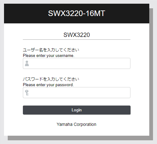
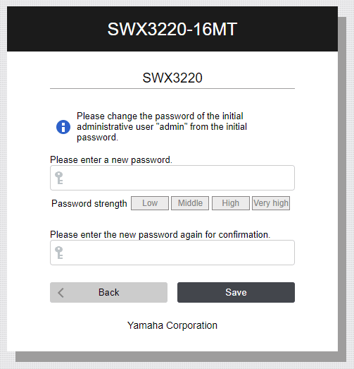
When access is successful, the following login screen is displayed.
If default settings are configured, log in by entering “admin” as the default administrative username (and “admin” as the password).
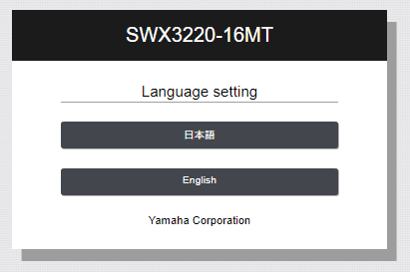
Given factory settings, when access from the browser and login is successful, a language selection screen is displayed.
Then specify a new password later, when prompted to change the default administrative password.
- Access from a Telnet Client
- After that, specify settings as appropriate for the given product operating environment.
- For details on specifying settings from a Telnet client or SSH client, refer to Command Reference.
- For details on specifying settings via a web browser, refer to Help within the GUI accessed.
Updating Firmware
To ensure reliable operation, we recommend applying the most recent firmware updates, which include new functionality and bug fixes.
Please verify your system version before applying updates.
- Use the show environment command to check the system version.
Precautions
- Please note that Yamaha accepts no responsibility for damage or losses that result from using the product or specifying settings incorrectly.
- If plugged into a 200 V AC power supply outlet, the customer is responsible for supplying an appropriate power cord. Note that Yamaha accepts no responsibility for any of various types of damage or losses caused by the power cord.
- Do not touch the inside of ports with fingers or metallic objects, etc.
- Do not install the product where it is exposed to direct sunlight or unusually high temperatures (such as next to a heater).
- Do not use the product in a location subject to sudden changes in ambient temperature. Sudden changes in ambient temperature could cause condensation to form on the product. If condensation forms, let it dry for a while before switching ON the power supply.
- Before touching this unit, remove static charge from yourself and your clothing.
- Do not place this unit in locations where there is a strong magnetic field.
- Do not connect equipment that generates noise to the same electrical power supply line as this unit. Such conditions might cause malfunctions or faulty operation.
- Using the product could cause noise to occur in nearby devices, such as telephones, radios, or televisions. If noise occurs, try relocating or reorienting the product.
- Do not route communication cables near power cords. Power cords could induce high voltages that might cause malfunction.
- Unplug the product from the power outlet while not in use.
- Use enhanced category 5 (CAT5e) or better LAN cable for 1000BASE-T connections.
- Use category 6 (CAT6) or better LAN cable for 10GBASE-T connections. However, the maximum transmission distance might be shorter than specified if used for 2.5GBASE-T/5GBASE-T/10GBASE-T connections, due to noise from adjacent cables or other external sources.
- If ownership of this product is conveyed to another party, be sure to provide this manual as well.
- This product includes a lithium-ion battery for backup power for clock functionality. Therefore, the product and its accessories are disposed of in accordance with local laws and regulations.
- To use an SFP+ port, install one of the following Yamaha modules sold separately. Functionality is not guaranteed if any module other than those indicated below is installed.
- YSFP-G-SXA、YSFP-G-LXA、SFP-SWRG-SX、SFP-SWRG-LX
- YSFP-10G-SR、YSFP-10G-LR、SFP-SWRT-SR、SFP-SWRT-LR
- YDAC-10G-3M、YDAC-10G-1M、DAC-SWRT-3M、DAC-SWRT-1M
- Attach a dust cover to all unused SFP and SFP+ ports. If foreign matter gets inside the port, it could cause a malfunction. Keep the dust covers carefully stored so they are not lost.
- SFP modules and optical fiber cables can have problems with insufficient light input, failure to link up, or other issues due to loss of accuracy caused by connector damage or abrasion, dirty contacts, or other factors. In particular, single mode fiber should be handled especially carefully because it is more prone to suffer such effects than multi mode fiber. Clean the contacts before making connections. Also, attach the protective cap when not in use.
- SWX3220 Series Technical Data (Basic Functions)
- Important notice
Login security
1 Function Overview
This product includes the following user account management improvements as countermeasures for ensuring cyber security.
To eliminate the risk of malicious cyber-attacks and ensure the product is used safely, be sure to read this document carefully and specify an appropriate user password before use.
For details, refer to User account management.
- Mandatory administrator registration
- At least one administrator account must be registered for this product.
Therefore, a default administrative user (username: admin and password: admin) has been specified for logging in to the product the first time.
- When first logging in, specify admin for both the username and password.
- After logging in using the default administrative user account, the user is prompted to change the password setting.
- At least one administrator account must be registered for this product.
- Stricter limits on guest user operations
- If the special privileged access password (default administrative password) has not been changed, the following operations that use a special privileged access password will be restricted.
- Users without administrator rights cannot switch to the privileged EXEC mode.
- Factory settings cannot be restored using CLI/ GUI operations.
- Connections as a TFTP server cannot be received.
- To perform the above operations, change the special privileged access password (default administrative password).
- If the special privileged access password (default administrative password) has not been changed, the following operations that use a special privileged access password will be restricted.
- Countermeasure for Brute-Force Attacks
- As a countermeasure against brute-force attacks, login restrictions are applied after a login fails.
- If an incorrect password is entered three successive times when logging into the switch via the console, Web GUI, or other means, login is disabled for one minute thereafter, even if the correct password is entered.
- If the password is entered incorrectly, wait at least one minute before trying to log in again.
2 Applicable models and revisions
User account management has been improved in the following models and revisions.
| Models | Revisions |
| SWX3220-16MT SWX3220-16TMs | Rev. 4.02.10 or later |
| SWX3200-52GT SWX3200-28GT | Rev. 4.00.25 or later |
| SWX3100-18GT SWX3100-10G | Rev. 4.01.29 or later |
| SWX2322P-16MT | Rev. 2.06.10 or later |
| SWX2320-16MT | Rev. 2.05.10 or later |
| SWX2310-52GT SWX2310-28GT SWX2310-18GT SWX2310-10G | Rev. 2.04.11 or later |
| SWR2310-28GT SWR2310-18GT SWR2310-10G | Rev. 2.04.12 or later |
| SWX2310P-28GT SWX2310P-18G SWX2310P-10G | Rev. 2.02.24 or later |
| SWR2311P-10G | Rev. 2.02.25 or later |
| SWP2-10SMF SWP2-10MMF | Rev. 2.03.16 or later |
3 Precautions when updating firmware
If the firmware is updated with stronger user account management functionality, be sure to register an administrator account according to the following procedure before using the switch.
- Register the administrator account with the previous firmware running, which has not been updated with stronger user account management functionality.
- If an administrator account already exists, then no account registration is necessary.
- However, if a password was not specified for the administrator account, be sure to specify a password.
- It is not a problem if the user name for the administrator account is the default “admin”.
Yamaha>enable
Yamaha#configure terminal
Yamaha(config)#username (username) privilege on password (password)
- Create guest user
If necessary, create a guest user as follows.- If using the username command, create it with the privilege option disabled (off).
Yamaha(config)#username (username) privilege off password (password)
- If using the username command, create it with the privilege option disabled (off).
- Change the special privileged access password (administrative password)
- The default special privileged access password (administrative password) setting is “admin”.
- To change the special privileged access password (administrative password) using a command, use the enable password command.
Yamaha(config)#enable password (special privileged access password)
- Update the firmware as described in
- Firmware update“update the firmware to the updated version”.
4 Related Documentation
- SWX3220 Series Technical Data (Basic Functions)
- Maintenance and operation functions
Maintenance and operation functions
- User account management
- LED control
- Using external memory
- Boot data management
- Viewing unit information
- System self-diagnostic
- Cable diagnostics
- Config management
- Remote access control
- Time management
- SNMP
- RMON
- SYSLOG
- Firmware update
- L2MS control
- Mail notification
- LLDP
- LLDP automatic setting
- Terminal monitoring
- Performance observation
- Scheduling function
- Dante optimization setting function
- SDVoE setting optimization function
- Stack function
- PTP
- Buzzer
- List of default settings
- SWX3220 Series Technical Data (Basic Functions)
- Maintenance and operation functions
- User account management
User account management
1 Function Overview
This product provides the functions shown below for managing user accounts.
- Functions for setting user information
- Functions for user authentication by user name and password
2 Definition of Terms Used
Default administrative user
Users with administrator rights specified in default factory settings.
Username: admin and Password: admin
Administrative user
Users with administrator rights.
Administrative users are users with the privilege option switched on using the username command.
Guest user
Users without administrator rights and that require entering the special privileged access password (administrative password) in order to access the privileged EXEC mode.
Guest users are users with the privilege option switched off using the username command.
Special privileged access password (administrative password)
The password used to assign administrator rights and specified using the enable password command.
Unnamed user
Users with a blank username setting.
Rev.4.02.09 or earlier firmware versions permitted using unnamed user accounts under factory default settings, but unnamed user accounts were eliminated newer firmware versions with stronger user account management functionality.
3 Function Details
3.1 User account function settings
3.1.1 Setting user information
Use the username command to specify the following user information.
- User name
- Password
- Assignment of administrator rights
With factory default settings, the administrative username and password are both “admin”.
3.1.2 Setting the special privileged access password (administrative password)
Special privileged access passwords (administrative passwords) are set using the enable password command.
Special privileged access passwords (administrative passwords) are used for the following applications.
- To initialize devices
- To transition users without administrator rights to the privileged EXEC mode.
- To use a TFTP client to send a config file or firmware to the switch
The factory default special privileged access password (default administrative password) setting is admin, but the operations described above cannot be performed if the special privileged access password (default administrative password) is set to the default setting.
To perform any of those operations, change the special privileged access password (default administrative password) in advance.
3.1.3 Administrator rights
User login operations can be restricted depending on whether or not the user has administrator rights.
- Administrative users (users with administrator rights) can change device settings or update firmware.
- Guest users (users without administrator rights) can only view device information without changing any settings.
Specifically, the following differences apply depending on whether or not the user has administrator rights.
| Console | Web GUI | |||
|---|---|---|---|---|
| Administrative user (with rights) | Guest user (without rights) | Administrative user (with rights) | Guest user (without rights) | |
| Show device information | ✓ | ✓ | ✓ | ✓ |
| View settings | ✓ | - | ✓ | Limited (*1) |
| Change settings | ✓ | - | ✓ | - |
| Restart or initialize devices | ✓ | - | ✓ | - |
| Update the firmware | ✓ | - | ✓ | - |
*1: Cannot view passwords or other security-related settings.
Once the enable command is executed and the special privileged access password (administrative password) is entered, the privileged EXEC mode can be accessed to perform operations equivalent to an administrative user, even if logged in as a guest user.
For information about the rights required to execute each command, refer to the command reference.
3.1.4 Password encryption
Specified passwords can be encrypted using the password-encryption command.
To encrypt a password, specify the password-encryption enable setting.
Once a password has been encrypted, it cannot be restored to an unencrypted character string state, even by specifying the password-encryption disable setting.
Encryption applies to the passwords specified by the following commands.
- enable password command
- username command
3.2 User authentication
3.2.1 When logging in to the console
When the following login prompt appears after connecting to the console, log in by entering the specified username and password.
Username:
Password:
For factory default settings, log in by entering “admin” as the default administrative username (and “admin” as the password).
After using “admin” to log in, the password must be changed to specify a new password.
Username: admin
Password:                                ... (Enter “admin”)

SWX3220-16MT Rev.4.02.00  (Fri Jan  1 00:00:00 2021)
  Copyright (c) 2018-2021 Yamaha Corporation. All Rights Reserved.

Please change the default password for admin.
New Password:                            ... (Enter new password.)
New Password(Confirm):                   ... (Enter the same password again.)
Saving ...
Succeeded to write configuration
If an incorrect password is entered three successive times, login by that same user is restricted for one minute.
Username: User
Password:
% Incorrect username or password, or login as User is restricted.
Password:
% Incorrect username or password, or login as User is restricted.
Password:
% Incorrect username or password, or blocked upon 3 failed login attempts for User.
% Please try again later.
If a login restriction occurs, the following message is output in the INFO level SYSLOG.
| Connection method | Output message |
| Serial console | Login access from serial console as {username} was restricted |
| TELNET | Login access from TELNET as {username} was restricted: {IP address} |
| SSH | Login access from SSH as {username} was restricted: {IP address} |
| Web GUI | Login access from HTTP as {username} was restricted: {IP address} |
Note that if a user with a login restriction enters an incorrect password again, the remaining time until the restriction is cancelled is reset to one minute again.
3.2.2 Logging into the Web GUI
When the following login form appears after accessing the Web GUI, log in by entering the specified username and password.
For factory default settings, log in by entering “admin” as the default administrative username (and “admin” as the password).
If logging in with factory default settings, a Web GUI language selection screen is displayed after logging in.
If prompted to change the password after using “admin” to log in, specify a new password.
3.3 What to do if you forget your login password
If the product is rebooted connected to the serial console and “I” (uppercase letter I) is entered during the booting process, the product can be rebooted with factory default settings.
BootROM - X.XX
Booting from SPI flash

SWX3220-16MT BootROM Ver.1.00      #### Enter “I” as soon as the boot ROM version is displayed. ####

Initialize or not ?(y/n) y

Loading config0 because can’t read config in SD card.
Starting ..............................................
Loading configuration ... Done!

SWX3220-16MT Rev.4.02.00  (Fri Jan  1 00:00:00 2021)
  Copyright (c) 2018-2021 Yamaha Corporation. All Rights Reserved.
4 Related Commands
The related commands are shown below.
For details, refer to the Command Reference.
List of related commands
| Operations | Operating commands |
|---|---|
| Setting the special privileged access password (administrative password) | enable password |
| Encrypt password | password-encryption |
| Set user | username |
| Show user information | show users |
5 Examples of Command Execution
5.1 Adding a user
The following example assigns administrator rights to the user “yamaha” and specifies the password “yamaha_pass”.
Yamaha#configure terminal
Enter configuration commands, one per line.  End with CNTL/Z.
Yamaha(config)#username yamaha privilege on password yamaha_pass
Yamaha(config)#exit
Yamaha#exit

Username: yamaha
Password:

SWX3220-16MT Rev.4.02.00  (Fri Jan  1 00:00:00 2021)
  Copyright (c) 2018-2021 Yamaha Corporation. All Rights Reserved.

Yamaha>enable
Yamaha#
6 Points of Caution
- If no administrative user (user with administrator rights) exists in startup-config when the product is booted, then a default administrative user (with username “admin”and password “admin”) will be added automatically.
For example, that would occur in the following case.
- Product is booted with factory default settings configured
- Firmware is updated to a newer version than Rev.4.02.09 after the product was operated using Rev.4.02.09 or older firmware only by an unnamed user.
- If a user with no password is specified in startup-config when the product is booted, then a password with the same character string as the username will be added automatically.
For example, that would occur in the following case.
- Firmware is updated to a newer version than Rev.4.02.09 after Rev.4.02.09 or older firmware was used to specify a user with no password.
Setting with Rev.4.02.09 or earlier firmware version
username yamaha1
username yamaha2 privilege on
Setting after updating firmware to a newer version than Rev.4.02.09
username yamaha1 password yamaha1
username yamaha2 privilege on password yamaha2
- Firmware is updated to a newer version than Rev.4.02.09 after Rev.4.02.09 or older firmware was used to specify a user with no password.
- If the password (admin) for the default administrative user admin is left unchanged, then the following restrictions are applied.
- Switches cannot be accessed by TELNET, SSH, HTTP, or HTTPS from a network segment other than the maintenance VLAN.
- Login by users other than the default administrative user is not permitted.
Username: yamaha
Password:
% Please login as user "admin".
- The following commands cannot be executed. Similar setting changes cannot be performed via the Web GUI either.
- ip address / no ip address
* However, only the ip address dhcp command can only be executed - auto-ip / no auto-ip
- ipv6 / no ipv6
- ipv6 address / no ipv6 address
- management interface / no management interface
- ip address / no ip address
7 Related Documentation
LED control
1 Function Overview
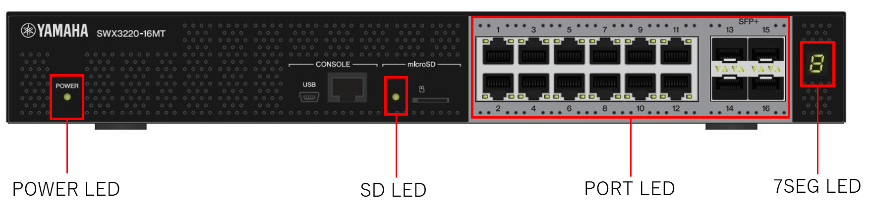
This product includes the following indicator lights on the main unit.
Indicator type
| Indicator type | Description |
|---|---|
| POWER Indicator | Indicates the power supply status. |
| microSD Indicator | Indicates the microSD card connection and usage status. |
| Port Indicators | Indicate the LAN/SFP cable connection and usage status. |
| Stack ID display (7-segment display) | Displays the stack number. |
The location of each indicator is shown below.
2 Definition of Terms Used
Port Indicator Illumination Guide
Port indicator illumination mentioned in subsequent explanations are illustrated below.
Port Indicator illumination guide

3 Function Details
3.1 POWER Indicator
The POWER indicator indicates the power supply status to this product.
The corresponding status for each POWER indicator illumination mode is described below.
POWER indicator illumination mode and status
| POWER Indicator Illumination Mode | Status |
|---|---|
| Unlit | Power is off. |
| Flashing green | Power is on and system is starting up. |
| Steady green | Power is on and system is operating normally. |
| Steady orange | Power is on and an error has occurred in the system. |
When the following errors are detected, the POWER indicator illuminates steady orange.
Check the error that was detected and take the appropriate actions.
Fan stopped
The fan that exhausts heat generated by the product has stopped.
Immediately stop using the product and be sure to contact the dealer for inspection or service.
Temperature error inside the product
The temperature inside the product is abnormal.
Review the ambient conditions where installed and install the product correctly so that internal temperature is appropriate.
Damage to area where config is saved
Config information is not read correctly during startup.
Contact the dealer for inspection and/or service.
You can use the show environment command to check temperature and fan errors.
3.2 microSD Indicator
The microSD indicator indicates the microSD card connection and usage status.
The illumination mode of the microSD indicator and the corresponding status is described below.
microSD indicator illumination mode and status
| microSD Indicator Illumination Mode | Status |
|---|---|
| Unlit | Not available, because a microSD card is not inserted or unmounted. |
| Flashing green | The microSD card is being accessed. |
| Steady green | A microSD card is inserted and available for use. |
Do not remove the microSD card while flashing green, because the microSD card is being accessed.
3.3 Port Indicators
3.3.1 Display Modes and Switching Between Them
This product offers the following three display modes.
| Mode Name | Switch Users | Function Overview |
|---|---|---|
| LINK/ACT Mode | ✓ | The left indicator of LAN/SFP ports indicates the link status and the right indicator indicates the connection speed. |
| STATUS Mode | - | Displays the error status of the LAN/SFP ports. |
| OFF Mode | ✓ | Switches off LAN/SFP port indicators to minimize power consumption. |
The display mode can be restored to the default setting (indicator mode after system startup) using the led-mode default command.
However, the STATUS mode only switches automatically, so cannot be switched manually by the user.
The flowchart below shows how the indicator mode changes.
Indicator mode transition sequence
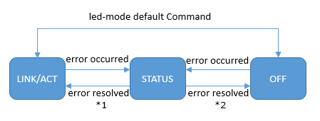
*1 Assuming the initial indicator mode is LINK/ACT
*2 Assuming the initial indicator mode is OFF
The indicator mode after system startup and the indicator mode after error is resolved depend on the default indicator mode setting.
If an error is detected by the following functions, the port indicators automatically switch to the STATUS mode.
- Loop detection
- SFP optical input level monitoring
The system will not transition from STATUS mode to LINK/ACT mode or OFF mode until all errors are resolved.
3.3.2 Indicators Displayed in LINK/ACT Mode
In the LINK/ACT mode, port indicators are illuminated as shown below.
- LAN/SFP port link status
- LAN/SFP port connection speed
The link status is indicated as shown below.
LAN/SFP port link status indicator display modes
| While Link is Down | While Link is Up | While Forwarding Data | |
|---|---|---|---|
| LAN Ports |  (Off) |  (Steady green) |  (Flashing green) |
| SFP Ports |  (Off) |  (Steady green) |  (Flashing green) |
The connection speed is indicated as shown below.
LAN/SFP port connection speed indicator display
| 100M Link | 1G Link | 2.5G/5G/10G Link | |
|---|---|---|---|
| LAN Ports |  (Off) |  (Steady orange) |  (Steady green) |
| SFP Ports | (none) |  (Steady green) |  (Steady green) |
3.3.3 Indicators Displayed in STATUS Mode
In STATUS mode, the port indicators indicate the status of errors generated by the following product functions.
- Loop detection
- SFP optical input level monitoring
The port indicator display modes during active errors are indicated below.
Port indicator display modes during active errors
| Normal State | Loop Detected or SFP Input Level Error | |
|---|---|---|
| LAN Ports |  (Off) |  (Left flashes orange) |
| SFP Ports |  (Off) |  (Left flashes orange) |
When the product detects an error, it overrides the current mode and switches to STATUS mode.
The following conditions trigger an error in respective functions.
- Loop detection
- Loop was detected, so port was blocked
- Loop was detected, so port was shut down
- SFP optical input level monitoring
- SFP optical input level fell below the normal range
- SFP optical input level exceeded the normal range
The cause of the error can be checked using the show error port-led command.
During active errors in the STATUS mode, indicators will automatically switch to the default indicator mode in the following states.
- All of the following errors were resolved.
- Blocked status due to loop detection is resolved.
- Shutdown status due to loop detection is resolved.
- The monitoring time elapsed after the shutdown due to loop detection.
- The unit linked up after the no shutdown command was executed during shutdown due to loop detection.
- SFP optical input level recovered.
3.3.4 Indicators Displayed in OFF Mode
If the default indicator mode is the OFF mode, the port indicators remain off regardless of the link status.
The stack ID indicators also switch off at the same time.
Even if the default indicator mode is OFF, if an error occurs then the mode automatically switches to the STATUS mode and displays the error status.
3.3.5 Changing the Indicator Mode after System Startup
This product enables the indicator mode after system startup (the default indicator mode) to be changed.
The initial default indicator mode is set to LINK/ACT mode, but it can be changed using the led-mode default command.
The default and current indicator modes can be checked using the show led-mode command.
If an active error is resolved in the STATUS mode, the mode is switched back to the default indicator mode.
3.3.6 Other Port Indicator Modes
Regardless of the indicator mode status, all port indicators will illuminate as indicated below during startup initialization and firmware updates.
Other port indicator modes
| Updating firmware | Initializing | |
|---|---|---|
| LAN Ports |  (Flashing green) |  (Steady orange) |
| SFP Ports |  (Flashing green) |  (Steady orange) |
3.4 Stack ID Display
After the countdown display during startup, the stack ID display (seven-segment display) displays the stack ID, if a stack is configured.
If a stack is not configured, the number ‘1’ is displayed.
If an error occurs while a stack is configured, the letter ’E’ is displayed to indicate the error.
If the default indicator mode is the OFF mode, the stack ID display is also switched off.
4 Related Commands
Related commands are indicated below.
For details on the commands, refer to the Command Reference.
List of related commands
| Operations | Operating Command |
|---|---|
| Show LAN/SFP port status | show interface |
| Show loop detection setting status | show loop-detect |
| Set default indicator mode | led-mode default |
| Show indicator mode | show led-mode |
| Show port error status | show error port-led |
5 Examples of Command Execution
5.1 Checking LAN/SFP Port Status
Use the show interface command to check the LAN/SFP port status.
Yamaha#show interface
show interface
Interface port1.1
  Link is UP
  Hardware is Ethernet
  HW addr: ac44.f23d.0b2c
  ifIndex 5001, MRU 1522
  Speed-Duplex: auto(configured), 1000-full(current)
  Auto MDI/MDIX: on
  Vlan info :
    Switchport mode        : access
    Ingress filter         : enable
    Acceptable frame types : all
    Default Vlan           :    1
    Configured Vlans       :    1
  Interface counter:
    input  packets          : 317111
           bytes            : 31387581
           multicast packets: 317074
    output packets          : 162694
           bytes            : 220469213
           multicast packets: 162310
           broadcast packets: 149
           drop packets     : 0
  :
(Shows information for all LAN/SFP ports)
5.2 Checking LAN/SFP Port Loop Detection Status
Check the LAN/SFP port loop detection status.
Yamaha#show loop-detect
loop-detect: Enable

loop-detect: Enable

port      loop-detect    port-blocking           status
-------------------------------------------------------
port1.1        enable           enable           Normal
port1.2        enable           enable           Normal
port1.3        enable           enable           Normal
port1.4        enable           enable           Normal
port1.5        enable           enable           Normal
port1.6        enable           enable           Normal
port1.7        enable           enable           Normal
port1.8        enable           enable           Normal
port1.9        enable           enable           Normal
port1.10       enable           enable           Normal
-------------------------------------------------------
(*): Indicates that the feature is enabled.
5.3 Setting the Default Indicator Mode
Set the default indicator mode to the OFF mode.
Yamaha#configure terminal
Yamaha(config)#led-mode default off … (Sets the default indicator mode)
Yamaha(config)#exit
YamahaW#show led-mode … (Displays the indicator mode)
default mode : off
current mode : off
- SWX3220 Series Technical Data (Basic Functions)
- Maintenance and operation functions
- Using external memory
Using external memory
1 Function Overview
This product provides the following functions using external memory.
- SD card boot (firmware, config)
- The system can be started using a firmware file and config file from an SD card.
- Applying SD card booting automatically (firmware, config)
- The firmware and config file used for SD card booting can be applied the next time the product is booted, even if the SD card is unavailable.
- Firmware update
- This unit’s firmware can be updated by loading a firmware file from an SD card.
- Saving and copying a config file
- The running-config that is currently running on the system can be saved to an SD card, and config files can be copied from the SD card to the unit’s flash ROM or from the unit’s flash ROM to the SD card.
- Saving a log file
- By executing the save logging command you can back up the log file to an SD card.
- Saving technical support information
- Technical support information (the result of executing the show tech-support command) can be saved to an SD card.
- Saving statistical information
- Observations of resource information and traffic information are backed up regularly.
- This statistical information can be saved as a CSV format file.
- Backing up and restoring system information
- System information (including configurations) can be backed up to an SD card.
- Backed up system information can be restored into the unit’s flash ROM.
2 Definition of Terms Used
None
3 Function Details
3.1 External memory that can be used
Requirements for external memory that can be used are as follows.
- Card type: microSD card / microSDHC card
- File format: FAT16/FAT32
3.2 Folder structure
The SD card must contain the following folder structure.
Device name	+-- firmware          Firmware file storage folder
 		|
 		|
 		+-- startup-config    Startup config storage folder
 		|
 		|
 		+-- log               SYSLOG storage folder
 		|
 		|
 		+-- techsupport       Technical support information storage folder
 		|
 		|
 		+-- data              System-wide folder
 		|
 		|
 		+-- backup-system     System backup folder
3.3 Mounting and unmounting the SD card
If the SD card is inserted when starting up or after startup, it is automatically mounted and becomes available.
To prevent loss of files, execute the unmount sd command or execute the unmount operation from the Web GUI before removing the SD card.
If the SD card is unmounted, it cannot be used.
If you want to once again use the SD card after executing the unmount sd command, you must execute the following.
- Remove and reinsert the SD card
- Execute the mount sd command
- Execute mount from the Web GUI
3.4 SD card boot (firmware, config)
The system can be started using a firmware file and config file from an SD card.
In order to use SD card boot, the following conditions must be satisfied.
- SD card using a firmware file
- The SD card is connected when the system starts up.
- The following files exist in the SD card.
- /swx3220/firmware/swx3220.bin
- boot prioritize sd enable is specified.
* With the factory settings, boot prioritize sd enable is specified.
- SD card boot using a config file
- The SD card is connected when the system starts up.
- The SD card includes the following files.
- /swx3220/startup-config/config.txt
- startup-config select sd is specified.
* With the factory settings, startup-config select sd is specified.
The file used for SD card booting can also be automatically saved to internal flash ROM memory using the automatic SD card booting function (see 3.5 Automatic SD card booting).
You can use the show environment command to check whether SD card boot was successful.
- In the case of SD card boot using a firmware file, “Startup Firmware” will indicate “exec(SD).”
- In the case of SD card boot using a config file, “Startup Configuration” will indicate “config(SD).”
In the case of SD card boot using a config file, executing the write and copy running-config startup-config commands will update the config file on the SD card.
If SD card boot using a config file fails, startup config #0 is loaded.
Also, the following message is shown in the console and in SYSLOG.
Loading config0 because can’t read config in SD card.
3.5 Automatic SD card booting (firmware, config)
The firmware and config used for SD card booting can be automatically saved to internal flash ROM memory.
This function can be used to easily install previously prepared firmware and config files in newly purchased devices (with factory settings).
3.5.1 Preparations before using automatic saving
In order to use this function, the following conditions must be satisfied.
- SD card booting is enabled by either of the following methods. (For details, see 3.4 SD card booting.)
- The boot prioritize sd enable command is specified and firmware is installed with an appropriate path for SD cards.
- startup-config select sd is specified and the config file is installed with an appropriate path.
- The automatic SD card booting function is enabled.
- The automatic SD card booting function can be enabled using the boot auto-apply enable command.
(Note: Enabled in default factory settings.)
- The show environment command “boot auto-apply” display results can be used to confirm whether the function is enabled or disabled.
- The automatic SD card booting function can be enabled using the boot auto-apply enable command.
- Prepare a file for automatically applying the automatic SD card booting function.
- If firmware is applied automatically
- Prepare an auto-apply.txt file (empty text file) in the firmware folder in the SD card.
/swx3220/firmware/auto-apply.txt
- Prepare an auto-apply.txt file (empty text file) in the firmware folder in the SD card.
- If a config file is applied automatically
- Prepare an auto-apply.txt file (empty text file) in the startup-config folder in the SD card.
/swx3220/startup-config/auto-apply.txt
- Prepare an auto-apply.txt file (empty text file) in the startup-config folder in the SD card.
- If firmware is applied automatically
3.5.2 Procedure for automatic SD card booting
Use the following procedure to automatically apply SD card booting.
- Implement preparations. (See 3.5.1 Preparations before using automatic saving)
- Insert the SD card and boot the switch.
- When SD card booting is finished, automatic save the specified file in internal flash memory. (Booting by automatic SD card booting takes longer than normal.)
- Save the results from automatic SD card booting. (See 3.5.3 Automatic SD card booting results.)
- Automatically unmount the SD card.
- Automatically switch off the microSD LED.
3.5.3 Automatic SD card booting results
Automatic SD card booting results are saved in the SD card.
- Automatic SD card booting results
File name and directory path Log /swx3220/startup-config/auto-apply-result.txt Serial : Date/time : Result /swx3220/firmware/auto-apply-result.txt Serial : Date/time : Result
3.5.4 Location for saving config file
To change the config location to a user-specified config ID, rename the auto-apply.txt file created, as indicated below.
If no config location is specified, the default config ID of 0 is applied.
- File name of each config file location
File name and directory path Config ID /swx3220/startup-config/auto-apply.txt 0 /swx3220/startup-config/auto-apply0.txt 0 /swx3220/startup-config/auto-apply1.txt 1
3.5.5 Precautions
Note the following precautions when using this function.
- When the automatic SD card booting is successful, the function is automatically disabled.
To avoid it being disabled automatically, the character string “keep” must be included at the top of the auto-apply.txt file created, as shown below.
keep
- This function is disabled if the stack function is enabled.
- If the SD card does not contain an auto-apply.txt file, the function is disabled.
- If the device was not booted from the SD card, the automatic SD card booting function will fail even if an auto-apply.txt file exists.
Refer to 3.4 SD card booting to confirm that the file in the SD card and the SD card booting function are enabled.
- If automatic SD card booting fails, only the SD card will be unmounted without automatically disabling the function.
- To prevent malfunction, be sure to delete the auto-apply.txt file if the automatic SD card booting function is not used.
3.6 Firmware update
This unit’s firmware can be updated by loading a firmware file from an SD card.
In order to use this function, the following conditions apply.
- The following files exist in the SD card.
- /swx3220/firmware/swx3220.bin
If the above file exists on the inserted SD card, executing the firmware-update sd execute command updates the firmware in flash ROM using the firmware in the SD card.
When the firmware-update sd execute command is executed, the user will be asked whether to maintain the mounted state of the SD card when the firmware file has finished loading. Remove the SD card as necessary after it is unmounted.
Note that if the SD card is left inserted during the automatic reboot in conjunction with firmware update, the system will start up with the firmware file on the SD card.
The firmware of the member switch can be updated by executing the firmware-update sd execute command from the main switch during stack configuration.
3.7 Saving and copying a config file
The running-config that is currently running on the system can be saved to the SD card. ( copy running-config startup-config command, write command)
You can copy the config file from the SD card to internal flash ROM, or from internal flash ROM to the SD card. ( copy startup-config command)
You can erase or show the startup-config in the SD card. ( erase startup-config command, show startup-config command)
The following folder in the SD card is affected.
- /swx3220/startup-config
3.8 Saving a log file
By executing the save logging command you can back up the log file to an SD card.
The logging backup sd command enables SYSLOG backup to the SD card.
If SYSLOG backup to the SD card is enabled, executing the save logging command will save the following log file with its save date to the SD card.
- /swx3220/log/YYYYMMDD_log.txt *YYYYMMDD=year month day
The log files in the SD card cannot be viewed or erased.
3.9 Saving technical support information
Technical support information (the result of executing the show tech-support command) can be saved to an SD card.
Executing the copy tech-support sd command will save the following technical support information file with its save date to the SD card.
- /swx3220/techsupport/YYYYMMDDHHMMSS_techsupport.txt *YYYYMMDD=year month day, HHMMSS=hours minutes seconds
The technical support information files in the SD card cannot be viewed or erased.
If the copy tech-support sd command is executed from the main switch in a stack configuration, a file containing technical support information for member switches is saved.
3.10 Saving statistical information
Observations of resource information and traffic information are backed up regularly.
To enable backup of statistical information to the SD card, you must make settings via the Web GUI in [Administration]–[Maintenance]–[Statistical information management].
This statistical information for the observed data can be saved via the Web GUI as a CSV format file.
3.11 Backup and restore of system information
This unit’s system information can be backed up to an SD card, and the backed up system information can be restored to a desired switch.
With an SD card connected to this unit, executing the backup system command will create a system information backup in the following folder.
- /swx3220/backup-system
If the file swx3220.bin exists in the /swx3220/firmware/ folder when backup is executed, it is backed up as a firmware file.
To restore the backed up system information, connect the SD card containing the system information backup to the desired switch, and execute the restore system command.
If the firmware file was backed up, a firmware update is also performed using that file.
When restore is completed, the system will restart.
The system information backup contains the following.
- Settings associated with the unit
- startup-config #0 - #1 and associated information
- startup-config select command setting values
- boot prioritize sd command setting values
- Firmware file
* Only if the specified folder of the SD card contained a firmware file when the backup was executed.
For this reason, when replacing a unit due to malfunction or another reason, the replacement unit can be returned to the same condition as the original unit simply by restoring the backed up system information.
Do not edit or delete the backed up system information.
4. List of related commands
The related commands are shown below.
For details, refer to the Command Reference.
List of related commands
| Operations | Operating Commands |
|---|---|
| Mount SD card | mount sd |
| Unmount SD card | unmount sd |
| Set SD card backup of log | logging backup sd |
| Back up log | save logging |
| Save technical support information | copy tech-support sd |
| Save running config | copy running-config startup-config |
| Save running config | write |
| Copy startup config | copy startup-config |
| Erase startup config | erase startup-config |
| Show startup config | show startup-config |
| Back up system information | backup system |
| Restore system information | restore system |
5 Examples of Command Execution
5.1 Unmount SD card
Unmount the SD card.
Yamaha>unmount sd
5.2 Mount SD card
Mount the SD card.
Yamaha>mount sd
5.3 Back up log file
By executing the save logging command you can back up the log file to the SD card as well.
Yamaha(config)#logging backup sd enable... (Enable SD card backup of log)
Yamaha(config)#exit
Yamaha#save logging ... (Back up log)
5.4 Saving technical support information
Save technical support information.
Yamaha#copy tech-support sd
6 Points of Caution
In rare cases, external memory can no longer be recognized after repeatedly inserting and removing the media.
The unit must be restarted to enable using the external memory again.
The following SYSLOG message is output when an error is detected.
microSD driver is dead. You must reboot the system to recover this condition.
7 Related Documentation
- SWX3220 Series Technical Data (Basic Functions)
- Maintenance and operation functions
- Boot data management
Boot data management
1 Function Overview
As system boot information, this product manages the information shown in the table below.
System boot information: items managed
| Management item | Description |
|---|---|
| System boot time | Time that the system booted up |
| Run-time firmware update | Firmware version currently running, and date generated |
| Firmware information for previous startup | Version and generated date of the firmware for the previous startup |
| Reason for boot | Reason why the system booted up. The following reasons for boot are recorded:
|
This product stores the current boot information and information on the previous four boots, for a total of five boot records.
2 Related Commands
The related commands are shown below.
For details on the commands, refer to the Command Reference.
List of related commands
| Operations | Operating Commands |
|---|---|
| Show boot information | show boot |
| Clear boot information | clear boot list |
3 Examples of Command Execution
3.1 Show boot information
This shows the current boot information.
Yamaha>show boot 0
 Running EXEC: SWX3220-16MT Rev.4.02.00  (Fri Jan  1 00:00:00 2021)
Previous EXEC: SWX3220-16MT Rev.4.02.00  (Fri Jan  1 00:00:00 2021)
Restart by reload command
This shows a list of the boot history.
Yamaha>show boot list
No. Date       Time     Info
--- ---------- -------- -------------------------------------------------
  0 2018/03/15 09:50:29 Restart by reload command
  1 2018/03/14 20:24:40 Power-on boot
--- ---------- -------- -------------------------------------------------
3.2 Clear boot information
This clears the boot information.
Yamaha#clear boot list
4 Points of Caution
If creation of the system information storage area at startup fails, the following message is output to the serial console screen.
At this time, all logs saved in the product are deleted.
- Message list
Message Detection timing Failed to create partition. When the system information storage area could not be created Succeeded to re-create partition. When the system information storage area was successfully recreated Boot sequence is interrupted by partition creation failure. When the system information storage area could not be created and the system could not start up
5 Related Documentation
None.
- SWX3220 Series Technical Data (Basic Functions)
- Maintenance and operation functions
- Viewing unit information
Viewing unit information
1 Function Overview
This product provides the following functionality that can be used to obtain product information, operating information, and so on.
- Use commands to show chassis information
- Obtain technical support information remotely
- Save technical support information on external memory
Technical support information includes a wide variety of data analysis information, including not only product information and operating information for this product, but also configuration information and process operating status information.
The functions can be used to show all information for a unit at the same time.
2 Function Details
2.1 Showing chassis information using commands
This function shows chassis information by entering a command in the console.
The following chassis information can be shown.
List of Chassis Information Shown
| Information Shown | Description | Command |
|---|---|---|
| Product information | Shows the product name, model number, product ID, and other information about the main unit. If an SFP module is inserted, product information about the module is also shown. | show inventory |
| Operating information | Shows product program operating information, such as boot software information, CPU usage rate, memory usage rate, and boot time. | show environment |
| Process list | Shows key information about the system and lists processes being executed. | show process |
| Memory usage status | Indicates the memory usage status for each process. | show memory |
| Disk usage status | Shows the percent of disk space being used by the system. | show disk-usage |
| Technical support information | Shows all available operating information as data analysis information necessary for technical support. If the stacking function is enabled, it shows technical support information for not only the main switch but also member switches. | show tech-support |
2.1.1 Showing product information
Product information for the main unit and SFP module can be shown using the show inventory command. Product information includes the following information.
- Name
- Description (DESCR)
- Vendor
- Product ID (PID)
- Version ID (VID)
- Serial No. (SN)
2.1.2 Showing operating information
System operating status can be shown using the show environment command. The system operating status includes the following information.
- Boot version
- Firmware revision
- Serial No.
- MAC address
- CPU usage rate
- Memory usage rate
- Fan operating status
- Fan rpm
- Firmware file
- Startup config file
- Setting the automatic SD card booting function
- Serial baud rate
- CPLD version
- Boot time
- Current time
- Elapsed time from boot
- Unit temperature status
- Unit temperature
2.1.3 Showing technical support information
Technical support information can be shown using the show tech-support command. Technical support information includes results from executing the following commands.
If stacking functionality is enabled, technical support information is shown for all devices configured in the stack.
However, the main and member switches execute different commands. For more details, see the command list below.
List of Executed Commands
| Command | Stacking Disabled | Stacking Enabled | |
|---|---|---|---|
| Main Switch | Member Switch | ||
| show running-config | ✓ | ✓ | ✓ |
| show startup-config | ✓ | ✓ | ✓ |
| show stack | ✓ | ✓ | ✓ |
| show environment | ✓ | ✓ | ✓ |
| show system-diagnostics | ✓ | ✓ | ✓ |
| show clock detail | ✓ | ✓ | - |
| show disk-usage | ✓ | ✓ | ✓ |
| show inventory | ✓ (*1) | ✓ (*1) | ✓ (*1) |
| show boot all | ✓ | ✓ | ✓ |
| show boot prioritize sd | ✓ | ✓ | ✓ |
| show fan history | ✓ | ✓ | ✓ |
| show logging | ✓ | ✓ | ✓ |
| show process | ✓ | ✓ | ✓ |
| show memory | ✓ | ✓ | ✓ |
| show users | ✓ | ✓ | ✓ |
| show interface | ✓ | ✓ | - |
| show frame-counter | ✓ | ✓ | - |
| show vlan brief | ✓ | ✓ | - |
| show spanning-tree mst detail | ✓ | ✓ | - |
| show etherchannel status detail | ✓ | ✓ | - |
| show loop-detect | ✓ | ✓ | - |
| show mac-address-table | ✓ | ✓ | - |
| show l2ms detail | ✓ | ✓ | - |
| show qos queue-counters | ✓ | ✓ | - |
| show ddm status | ✓ (*1) | ✓ (*1) | ✓ (*1) |
| show errdisable | ✓ | ✓ | - |
| show auth status | ✓ | ✓ | - |
| show auth supplicant | ✓ | ✓ | - |
| show error port-led | ✓ | ✓ | - |
| show ip interface brief | ✓ | ✓ | - |
| show ip forwarding | ✓ | ✓ | - |
| show ipv6 interface brief | ✓ | ✓ | - |
| show ipv6 forwarding | ✓ | ✓ | - |
| show ip route | ✓ | ✓ | - |
| show ip route database | ✓ | ✓ | - |
| show ip route pbr | ✓ | ✓ | - |
| show ipv6 route | ✓ | ✓ | - |
| show ipv6 route database | ✓ | ✓ | - |
| show ipv6 route pbr | ✓ | ✓ | - |
| show arp | ✓ | ✓ | - |
| show ipv6 neighbors | ✓ | ✓ | - |
| show ip rip | ✓ | ✓ | - |
| show ip rip interface | ✓ | ✓ | - |
| show ipv6 rip | ✓ | ✓ | - |
| show ipv6 rip interface | ✓ | ✓ | - |
| show ip ospf | ✓ | ✓ | - |
| show ip ospf database | ✓ | ✓ | - |
| show ip ospf interface | ✓ | ✓ | - |
| show ip ospf neighbor | ✓ | ✓ | - |
| show ip ospf route | ✓ | ✓ | - |
| show ipv6 ospf | ✓ | ✓ | - |
| show ipv6 ospf database | ✓ | ✓ | - |
| show ipv6 ospf interface | ✓ | ✓ | - |
| show ipv6 ospf neighbor | ✓ | ✓ | - |
| show ipv6 ospf route | ✓ | ✓ | - |
| show ip mroute | ✓ | ✓ | - |
| show ip mroute summary | ✓ | ✓ | - |
| show ip mroute count | ✓ | ✓ | - |
| show ip igmp groups | ✓ | ✓ | - |
| show ip igmp interface | ✓ | ✓ | - |
| show ip igmp ssm-map | ✓ | ✓ | - |
| show ip pim bsr-router | ✓ | ✓ | - |
| show ip pim interface detail | ✓ | ✓ | - |
| show ip pim mroute detail | ✓ | ✓ | - |
| show ip pim neighbor detail | ✓ | ✓ | - |
| show ip pim nexthop | ✓ | ✓ | - |
| show ip pim rp mapping | ✓ | ✓ | - |
| show ip igmp snooping groups | ✓ | ✓ | - |
| show ip igmp snooping interface | ✓ | ✓ | - |
| show ipv6 mld snooping groups | ✓ | ✓ | - |
| show ipv6 mld snooping interface | ✓ | ✓ | - |
| show vrrp | ✓ | ✓ | - |
| show dhcp server | ✓ | ✓ | - |
| show dhcp binding | ✓ | ✓ | - |
| show dhcp relay | ✓ | ✓ | - |
| show dns-forwarding | ✓ | ✓ | - |
| show dns-forwarding cache | ✓ | ✓ | - |
| show radius-server local certificate status | ✓ | ✓ | - |
| show radius-server local nas | ✓ | ✓ | - |
| show radius-server local user | ✓ | ✓ | - |
| show radius-server local certificate list | ✓ | ✓ | - |
| show radius-server local certificate revoke | ✓ | ✓ | - |
*1 Not included if obtained by TFTP.
2.2 Obtaining technical support information remotely
Technical support information (output results from show tech-support) can be obtained from the product by remote access via the Web GUI or TFTP.
2.2.1 Web GUI
Use the following procedure to configure a network environment that enables remote access, so that the product can use http server functionality.
- Decide which VLAN to use for maintenance.
- Specify an IPv4 address for the maintenance VLAN. Use the ip address command to specify the IPv4 address.
- Permit the maintenance VLAN to access the http server. To specify a different VLAN than for management interface command settings, use the http-server interface command.
Execute the following operations by accessing the Web GUI.
- Show technical support information on the Web GUI
- On the [TECHINFO] menu, click the [Show in browser] button to show the show tech-support command results in a sub-window.
- To stop showing the results, click the web browser close button.
- Obtain technical support information from the Web GUI
- On the [TECHINFO] menu, click the [Obtain as text file] button to automatically start downloading the file.
- The file is saved with a file name in the following format.
- techinfo_YYYYMMDDhhmmss.txt (where “YYYYMMDDhhmmss” is the date/time the command was executed)
2.2.2 TFTP
Use the following procedure to configure a network environment that enables remote access, so that the product can use tftp server functionality.
- Decide which VLAN to use for maintenance.
- Specify an IPv4 address for the maintenance VLAN. Use the ip address command to specify the IPv4 address.
- Permit access from the maintenance VLAN to the tftp server. To specify a different VLAN than for management interface command settings, use the tftp-server interface command.
If using a tftp client, specify techinfo in the remote path for obtaining technical support information.
2.3 Saving technical support information on external memory
The product can save technical support information (output results from show tech-support) on an SD memory card by using the copy tech-support sd command.
The SD card must be inserted before executing the command.
File names are saved in the following format on the SD card.
- /swx3220/techsupport/YYYYMMDDHHMMSS_techsupport.txt (where “YYYYMMDDHHMMSS” is the date/time the command was executed)
3 Related Commands
Related commands are indicated below.
For command details, refer to the command reference.
List of related commands
| Operations | Operating Command |
|---|---|
| Show product information | show inventory |
| Show operating information | show environment |
| Process list | show process |
| Memory usage status | show memory |
| Disk usage status | show disk-usage |
| Show technical support information | show tech-support |
| Save technical support information | copy tech-support sd |
4 Examples of Command Execution
4.1 Showing product information
The following shows product information for the main unit and SFP module.
Yamaha>show inventory
NAME: L3 switch
DESCR: SWX3220-16MT
Vendor: Yamaha
PID: SWX3220-16MT
VID: 0000
SN: S00000000

NAME: SFP1
DESCR: 1000BASE-LX
Vendor: YAMAHA
PID: YSFP-G-LX
VID: 0000
SN: 00000000000

NAME: SFP2
DESCR: 1000BASE-SX
Vendor: YAMAHA
PID: YSFP-G-SX
VID: 0000
SN: 00000000000
4.2 Showing operating information
The following shows the system operating status.
Yamaha>show environment
SWX3220-16MT BootROM Ver.1.00
SWX3220 Rev.4.02.00 (Fri Jan  1 00:00:00 2021)
main=SWX3220-16MT ver=00 serial=S00000000 MAC-Address=00a0.de00.0000
CPU:   2%(5sec)   2%(1min)   1%(5min)    Memory:  20% used
Fan status: Normal
Fan speed: FAN1=3629RPM FAN2=3698RPM FAN3=3698RPM
Startup firmware: exec0
Startup Configuration file: config0
             selected file: config0
Boot auto-apply: Enable
Serial Baudrate: 9600
CPLD version: 10
Boot time: 2021/01/01 00:00:00 +09:00
Current time: 2021/01/02 00:00:00 +09:00
Elapsed time from boot: 1days 00:00:00
Temperature status: Normal
Temperature: 39 degree C
4.3 Showing technical support information
The following shows technical support information.
Yamaha#show tech-support
#
# Information for Yamaha Technical Support
#

*** show running-config ***
!
!  - Running Configuration -
!  Current Time:  Fri Jan 1 00:00:00 JST 2021
!
dns-client enable
!
vlan database
 vlan 2 name VLAN0002
 vlan 3 name VLAN0003
!
interface port1.1
 switchport
 switchport mode access
...

*** show startup-config ***
...

*** show stack ***
...

*** show environment ***
...

*** show disk-usage ***
...
...
...

#
# End of Information for Yamaha Technical Support
#
5 Points of Caution
- Product internal temperature errors
- If the internal temperature in the product exceeds the threshold value, a temperature error (temperature alarm) is detected. If an internal temperature error is detected, promptly reassess the system operating environment and implement corrective measures to restore normal temperatures.
- If a temperature error (TempAlarm) is detected, it is output as follows.
- Example of SYSLOG output results
[ FANC]:inf: Temp Alarm CPU
- Example of operating information displayed
Yamaha>show environment
SWX3220-16MT BootROM Ver.1.00
SWX3220 Rev.4.02.00 (Fri Jan  1 00:00:00 2021)
...
...
Temperature status: Error (Exceeded alarm temperature CPU)
- Example of SYSLOG output results
6 Related Documentation
None
- SWX3220 Series Technical Data (Basic Functions)
- Maintenance and operation functions
- System self-diagnostic
System self-diagnostic
1 Function Overview
This product includes system self-diagnostic function.
The system self-diagnostic function detects the following types of errors.
- Startup process errors
- Hardware component errors
- Interface (Ethernet port)
- RTC
- CPLD
- SFP
- Fan
- Memory error
- Temperature error
2 Definition of Terms Used
Real-time clock (RTC)
Device used to manage time
CPLD(Complex Programmable Logic Device)
A type of programmable logic device.
Packet processor
Device used to process packets.
3 Function Details
3.1 Diagnostics
Three types of system self-diagnostic functionality, either bootup diagnostics, on-demand diagnostics, or health monitoring diagnostics, are available depending on when diagnostics are performed.
The features of each type are indicated below.
- Bootup diagnostics
- Automatically executed whenever the system starts up.
- Detects startup process errors and hardware component errors (RTC, etc.).
- On-demand diagnostics
- Can be executed at user-specified times set using the system-diagnostics on-demand execute command.
- Detects hardware component errors (interface, etc.) and memory errors
- All ports are shut down during diagnostics and the system is rebooted when finished.
- Health monitoring diagnostics
- Running continuously in the background during system operation.
- Detects hardware component errors (fan errors, etc.) and temperature errors
- Health monitoring diagnostic results are displayed via the GUI and LED indicators (only some test results are indicated via the LED indicators).
Each diagnosis runs multiple tests. The tests performed for each diagnosis are indicated below.
For a detailed list of tests performed, refer to 4 Test Details.
| Test Type | Bootup diagnostics | On-demand diagnostics | Health monitoring diagnostics |
|---|---|---|---|
| Loading Test | ✓ | ||
| RTC Test | ✓ | ||
| Packet Processor Test | ✓ | ||
| PHY Test | ✓ | ||
| CPLD Test | ✓ | ||
| Memory Test | ✓ | ||
| Thermal Test | ✓ | ||
| Fan Test | ✓ | ||
| SFP Test | ✓ |
3.2 Diagnostic results displayed
Diagnostic results can be checked using the show system-diagnostics command.
Though the system is automatically rebooted after on-demand diagnostics, diagnostic results can be confirmed after rebooting.
3.3 Deleting on-demand diagnostic results
On-demand diagnostic results can be deleted using the clear system-diagnostics on-demand command.
4 Test Details
Details about each test item are indicated below.
4.1 Loading test
This verifies the software module loading status.
A “Pass” result is output if all modules are successfully loaded, whereas a “Fail” result is output if even one module fails to load.
The show system-diagnostics command does not indicate information about modules that failed to load.
To identify which module failed to load, use the show logging command to search the following log. Note: In this example, the module name is indicated by “XXXX” characters.
[ HAMON]:err: An unexpected error has occurred. (XXXX deamon)
4.2 RTC test
This verifies access to the RTC register.
A time value is obtained from the RTC two times, resulting in “Pass” if the time value changed or “Fail” if the time values are identical.
A “Fail” result also occurs if the test fails to obtain a time value from the RTC (or load the register).
4.3 Packet processor test
This verifies access to the packet processor register.
A “Pass” result occurs if the value written in the packet processor register matches the loaded value, whereas a “Fail” result occurs if the values do not match.
A “Fail” result also occurs if the test fails to access the register.
4.4 PHY test
This verifies access to the PHY register.
A “Pass” result occurs if the value written in the PHY register matches the loaded value, whereas a “Fail” result occurs if the values do not match.
A “Fail” result also occurs if the test fails to access the register.
4.5 CPLD test
This verifies access to the CPLD register.
A “Pass” result occurs if the value written in the CPLD register matches the loaded value, whereas a “Fail” result occurs if the values do not match.
A “Fail” result also occurs if the test fails to access the register.
4.6 Memory Test
This verifies access to the packet processor memory.
It writes and reads values at various regions of the packet processor memory and then returns a “pass” result if the read value matches the written value or a “fail” result if they do not match.
A “fail” result also occurs if memory access fails.
4.7 Thermal Test
This monitors the CPU, MAC, PHY, and SFP module temperatures.
If the temperature exceeds a threshold value, a warning is indicated.
4.8 Fan Test
This monitors the fan rpm.
It indicates a warning if the fan stops rotating or the rotation speed increases.
4.9 SFP test
This monitors the SFP module optical input level.
It generates a warning if the optical input level exceeds a certain range.
5 Related Commands
Related commands are indicated below.
For details on the commands, refer to the Command Reference.
List of related commands
| Operations | Operating commands |
|---|---|
| Display system self-diagnostic results | show system-diagnostics |
| Execute on-demand diagnostics | system-diagnostics on-demand execute |
| Delete on-demand diagnostic results | clear system-diagnostics on-demand |
6 Examples of Command Execution
6.1 Displaying system self-diagnostic results
- Check the system self-diagnostic results as follows.
Yamaha#show system-diagnostics
Test results: (P = Pass, F = Fail, U = Untested, N = Normal, W = Warning)

- Bootup
  Loading Test: Pass

  RTC Test: Pass

  Packet Processor Test: Pass

- On-demand
Last on-demand diagnostics information:
 Date     : 2021/07/07 09:00:00 +09:00
 BootROM  : Ver.1.00
 Firmware : Rev.4.02.08
 CPLD     : Ver.16
 PHY      : Ver.10.5.0.0

  PHY Test:
    Port   1   2   3   4
    --------------------
           P   P   P   P

  CPLD Test: Pass

  Memory Test: Pass

- Health monitoring
  Thermal Test:
    CPU: Normal, MAC: Normal, PHY: Normal, SFP: Normal

  Fan Test: Normal

  SFP Test:
    Port   5   6   7   8   9  10  11  12  13  14  15  16
    ----------------------------------------------------
           N   N   N   N   N   N   N   N   N   N   N   N
6.2 Executing on-demand diagnostics
- Execute on-demand diagnostics as follows.
Yamaha#system-diagnostics on-demand execute
The system will be rebooted after diagnostics. Continue ? (y/n) y
on-demand diagnostics completed (pass). reboot immediately...
6.3 Deleting on-demand diagnostic results
- Delete on-demand diagnostic results as follows.
Yamaha#clear system-diagnostics on-demand
7 Points of Caution
- All ports are automatically shut down and rebooted whenever on-demand diagnostics is executed. Therefore, use particular caution before executing on-demand diagnostics while the system is being operated.
- On-demand diagnostics are only executed if the stack status is standalone or disabled. To perform on-demand diagnostics when a stack is configured, first disconnect the connections between member switches.
- If online diagnostics is executed remotely, such as via Telnet or the web console, simplified results cannot be displayed before rebooting because all ports are shut down during diagnostics. Use the show system-diagnostics command to check diagnostic results after rebooting.
8 Related Documentation
None
Cable diagnostics
1 Function Overview
The cable diagnostic function can be used to easily check whether or not the LAN cable connected to the LAN port has a faulty connection/circuit.
It can be used to troubleshoot network problems or as an easy way to check cables when setting up networks.
2 Definition of Terms Used
TDR (Time Domain Reflector)
The TDR is used to measure the length of LAN cables or the location of damage based on the reflected signals from a pulse signal sent through the LAN cables.
3 Function Details
3.1 How to diagnose cables
The cable diagnostic function can easily diagnose LAN cables using the time domain reflection (TDR) method.
Cable diagnostics is started by executing the cable-diagnostics tdr execute interface command.
If the show cable-diagnostics tdr command is executed after the diagnostics process is finished, the following diagnostic results are displayed.
| Item | Description |
|---|---|
| Cable status | The following cable states can be detected. ・ OK: The cable is electrically connected. ・ Open: Either no device is connected on the opposite end or the cable is faulty. ・ Short: A short circuit occurred. Results are displayed for each pair. |
| Distance to cable fault | If the cable status is “Open” or “Short”, then the distance to the fault is displayed. Results are displayed for each pair. |
Results from executing cable diagnostics the previous time can be checked using the show cable-diagnostics tdr command.
Only the immediately previous diagnostic results are retained and then overwritten the next time the cable diagnostics command is executed again.
The immediately previous results can be deleted using the clear cable-diagnostics tdr command.
4 Related Commands
Related commands are indicated below.
For command details, refer to the command reference.
List of related commands
| Operations | Operating commands |
|---|---|
| Execute cable diagnostics | cable-diagnostics tdr execute interface |
| Display cable diagnostics | show cable-diagnostics tdr |
| Clear cable diagnostic results | clear cable-diagnostics tdr |
The following commands included in smart switches can be used in the same way as the commands above.
- test cable-diagnostics tdr interface
- show test cable-diagnostics tdr
- clear test cable-diagnostics tdr
5 Examples of Command Execution
5.1 Executing cable diagnostics
Diagnose of the LAN cable connected to port 1.1 as follows.
Yamaha# test cable-diagnostics tdr interface port1.1
The port will be temporarily down during test. Continue? (y/n): y
% To check result, enter “show cable-diagnostics tdr”
5.2 Checking previous diagnostic results
Display the previous diagnostic results as follows.
Yamaha# show test cable-diagnostics tdr
Last run on Tue May 31 18:12:13 2022
Port      Pair  Status  Fault distance
-------------------------------------------
port1.1   1     OK      -
          2     OK      -
          3     Open    15  m
          4     Open    15  m
6 Points of Caution
- This function performs simplified diagnostics. Note that it cannot be used to for precision diagnosis of more specialized equipment.
- Cables 10 m or longer can be diagnosed. Cables shorter than 10 m cannot be diagnosed in some cases.
- Communication is temporarily stopped during cable diagnostics.
- Diagnostics cannot be performed if a shutdown command is specified for a corresponding port or the port is shut down either because a loop was detected or for any other reason.
- Diagnostics cannot be performed properly in some cases if the port on the opposite end is linked at a speed less than 1 Gbps.
- Diagnostics cannot be performed properly if PoE power is supplied at a corresponding port.
- If a stack is configured, commands cannot be executed from member switches in the stack.
7 Related Documentation
- None
Config management
1 Function Overview
This product uses the following config information to maintain the value of settings.
Table 1.1 Config types
| Config type | Description | User operations possible |
|---|---|---|
| Running config (running-config) | The currently-running setting values. Managed in RAM. | View / Save to startup config |
| Startup config (startup-config) | Saved setting values. Two config files are maintained in ROM, and one on the SD card. When the system starts up, either the config from ROM that is selected by the startup-config select command or the config from the SD card is loaded. The configuration on the SD card is controlled in the “/swx3220/startup-config” folder. | View / delete / copy |
| Default config (default-config) | The default setting values. Managed in ROM. | No operations possible |
2 Definition of Terms Used
None
3 Function Details
3.1 Running config
running-config is the settings that are currently operating; since it is maintained in RAM, it is destroyed at reboot.
On this product, commands executed in configuration mode are immediately applied to running-config, and the unit operates according to these settings.
The contents of running-config can be viewed by using the show running-config command.
3.2 Startup config
startup-config is settings that are saved in flash ROM or on the SD card, and the contents are preserved through reboot.
When this product is started, the settings of startup-config are applied as the initial settings of running-config.
This product can maintain two startup configs in flash ROM and one startup config on the SD card.
The startup-config data in the internal flash ROM is managed with an ID of 0–1, and the config on the SD card is managed with the keyword “sd”.
To specify which of the five types of config in the unit’s flash ROM are used, use the startup-config select command.
- By default, sd is used.
- When executing the startup-config select command, the user selects whether to restart. If you don’t restart, no change occurs in the command setting.
If you choose to restart, the unit restarts with the startup-config of the ID specified by the user’s command.
For easier management, you can use the startup-config description command to give each config a Description (explanatory text).
If you attempt to start up in a state where startup-config does not exist, such as after executing the cold start command, the default-config is automatically applied.
The running-config settings can be saved in startup-config by the copy running-config startup-config command or the write command.
The contents of startup-config can be erased by the erase startup-config command, viewed by the show startup-config command, and copied by the copy startup-config command.
3.3 Default config
default-config contains settings saved in internal flash ROM that are needed for this product to operate minimally as a switch. Like startup-config, the contents are preserved even after a restart.
The factory settings are maintained as default-config.
If startup-config does not exist when the system starts, default-config is copied to startup-config, and applied to running-config.
The contents of default-config cannot be viewed.
3.4 Deciding the config file at startup
The following describes the flow for deciding the config file used when this product starts up.
- The startup-config select command setting is referenced to determine the startup-config that will be used.
If the startup-config select command has specified sd, and an SD card on which startup-config is saved is not inserted, then startup-config #0 is selected.
- If the determined startup-config exists, the corresponding data is applied as running-config in RAM.
If the startup-config determined according to the value of the startup-config select command does not exist in ROM, then default-config is applied to RAM.
If startup using the config in the SD card fails, the following message is shown in the console and in SYSLOG.
Loading config0 because can’t read config in SD card.
3.5 Controlling the config file via TFTP
If this product’s TFTP server function is enabled, a TFTP client installed on a PC or other remote terminal can be used to perform the following.
- Acquire the currently running running-config and startup-config
- Apply a previously prepared settings file as startup-config
In order for the TFTP server to function correctly, an IP address must be specified for the VLAN.
Also, specify the administrative password in the form “/PASSWORD” appended to the end of the remote path.
However, the config file cannot be obtained or specified if the default administrative password is still specified. The administrative password setting must be changed in advance.
The startup-config settings are applied as running-config after the system is restarted.
Table 3.1 Remote path for applicable files (No automatic restart)
| Target CONFIG | Target file | Remote path | Get (GET) | Setting (PUT) | Automatic restart |
|---|---|---|---|---|---|
| running-config | CONFIG file (.txt) | config | ✓ | ✓ | - |
| startup-config # 0 | CONFIG file (.txt) | config0 | ✓ | ✓ | - |
| All settings (.zip) | config0-all | ✓ | ✓ | - | |
| startup-config # 1 | CONFIG file (.txt) | config1 | ✓ | ✓ | - |
| All settings (.zip) | config1-all | ✓ | ✓ | - | |
| startup-config # SD | CONFIG file (.txt) | configsd | ✓ | ✓ | - |
| All settings (.zip) | configsd-all | ✓ | ✓ | - |
If you want to restart the system automatically after applying the CONFIG file, specify the following remote path.
The currently running configuration is applicable.
Table 3.2 Remote path for applicable files (with automatic restart)
| Target CONFIG | Target file | Remote path | Get (GET) | Setting (PUT) | Automatic restart |
|---|---|---|---|---|---|
| Currently running startup-config | CONFIG file (.txt) | reconfig | - | ✓ | ✓ |
| All settings (.zip) | reconfig-all | - | ✓ | ✓ |
When applying (PUT) a CONFIG file, confirm that the target CONFIG and the type of the target file are correct.
If an incorrect file is specified, it cannot be reflected correctly.
In the case of running-config, it is necessary to add the following at the start of the CONFIG file.
!
! Switch Configuration
!
- The startup-config settings are applied as running-config when the system restarts.
4 Related Commands
The related commands are shown below.
For details, refer to the Command Reference.
List of related commands
| Operations | Operating Commands |
|---|---|
| Save running config | copy running-config startup-config |
| Save running config | write |
| Copy startup config | copy startup-config |
| Erase startup config | erase startup-config |
| Show startup config | show startup-config |
| Select startup config | startup-config select |
| Set description for startup config | startup-config description |
5 Examples of Command Execution
5.1 Select startup config
Select startup-config #1 and restart.
Yamaha#startup-config description 1 TEST ... (Assign the description “TEST” to startup-config #1)
Yamaha#startup-config select 1 ... (Select startup-config #1)
reboot system? (y/n): y  ... (Restart)
5.2 Save running config
Save running-config.
Yamaha#copy running-config startup-config
Suceeded to write configuration
Yamaha#
5.3 Copy startup config
Copy startup-config #1 to the SD card.
Yamaha#copy startup-config 1 sd  ... (Copy startup-config #1 to SD card)
Suceeded to copy configuration
Yamaha#show startup-config sd  ... (Show startup-config of SD card)
!
!  Last Modified: Tue Mar 13 17:34:02 JST 2018
!
dns-client enable
!
interface port1.1
 switchport
 switchport mode access
 no shutdown
!
...
5.4 Erase startup config
Erase startup-config from the SD card.
Yamaha#erase startup-config sd  ... (Erase startup-config of SD card)
Suceeded to erase configuration
Yamaha#
6 Points of Caution
None
7 Related Documentation
- SWX3220 Series Technical Data (Basic Functions)
- Maintenance and operation functions
- Remote access control
Remote access control
1 Function Overview
This product lets you restrict access to the following applications that implement network services.
- TELNET server
- SSH server
- HTTP server / HTTPS server
- TFTP server
- SNMP server
2 Definition of Terms Used
None
3 Function Details
The following four functions are provided to limit access to network services.
- Control whether to leave the service in question running in the background on the system (start/stop control)
- Change reception port number
- Limit access destinations for services currently running
- Limit the source IP addresses that can access services currently running
The following functions that correspond to each network service are shown in the table below.
Network service access control
| Network service | Start/stop control | Change reception port number | Limit access destinations | Limit access sources |
|---|---|---|---|---|
| TELNET server | ✓ | ✓ | ✓ | ✓ |
| SSH server | ✓ | ✓ | ✓ | ✓ |
| HTTP server HTTPS server | ✓ | ✓ | ✓ | ✓ |
| TFTP server | ✓ | ✓ | ✓ | - |
| SNMP server | -(Always booted) | -(Always 161) | - | ✓ |
- Multiple instances of a network service cannot be started.
If the start control is applied to the same service that is currently running, the service will restart. Consequently, any connected sessions will be disconnected.
- Access destinations for network services limited with respect to the VLAN interface.
- Sources permitted to access network services can be restricted by specifying access source IP address and access permit/deny settings.
- The default settings for the network services are shown in the table below.
Network service Start/stop status Reception port number Access destination restriction Access source restriction TELNET server run 23 Only default management VLAN (VLAN #1) permitted Allow all SSH server stop 22 Only default management VLAN (VLAN #1) permitted Allow all HTTP server run 80 Only default management VLAN (VLAN #1) permitted Allow all HTTPS server stop 443 TFTP server stop 69 Only default management VLAN (VLAN #1) permitted Allow all SNMP server run 161 Allow all Allow all
4 Related Commands
Related commands are shown below.
For details, refer to the Command Reference.
List of related commands
| Network service | Operations | Operating commands |
|---|---|---|
| Common | Management VLAN | management interface |
| TELNET server | Start/stop | telnet-server |
| Change reception port number | telnet-server enable (use argument to specify port number) | |
| Access control | telnet-server interface | |
| IP address access control | telnet-server access | |
| Show settings | show telnet-server | |
| SSH server | Start/stop | ssh-server |
| Change reception port number | ssh-server enable (use argument to specify port number) | |
| Access control | ssh-server interface | |
| IP address access control | ssh-server access | |
| Check whether client is alive | ssh-server client alive | |
| Show settings | show ssh-server | |
| Generate host key | ssh-server host key generate | |
| Clear host key | clear ssh-server host key | |
| Show public key | show ssh-server host key | |
| HTTP server | Start/stop HTTP server | http-server |
| Change HTTP server reception port number | http-server enable (use argument to specify port number) | |
| Start/stop HTTPS server | http-server secure | |
| Change HTTPS server reception port number | http-server secure enable (use argument to specify port number) | |
| Access control | http-server interface | |
| IP address access control | http-server access | |
| Show settings | show http-server | |
| TFTP server | Start/stop | tftp-server |
| Access control | tftp-server interface | |
| SNMP server | Access control by IP address and community name | snmp-server access |
5 Examples of Command Execution
5.1 TELNET server access control
This example restricts access to the TELNET server.
Change the TELNET server’s reception port to 1024.
Change the management VLAN to VLAN #1000 and allow access. Access from other than the management VLAN is denied.
Connection to the TELNET server is allowed only by clients from 192.168.100.1.
If you specify telnet-server access, access from IP addresses that do not meet the conditions is denied.
Yamaha(config)#telnet-server enable 1024 ... (Change reception port to 1024 and restart Telnet server)
Yamaha(config)#management interface vlan1000 ... (Permit access for VLAN #1000 as the maintenance VLAN)
Yamaha(config)#telnet-server access permit 192.168.100.1 ... (Permit access only from 192.168.100.1)
Yamaha(config)#end
Yamaha#show telnet-server ... (Check state of settings)
Service:Enable
Port:1024
Management interface(vlan):1000
Interface(vlan):None
Access:
    permit 192.168.100.1
5.2 SSH server access control
This example restricts access to the SSH server.
Generate the SSH server host key.
Register a user name and password.
Login from an SSH client is possible only for a registered user and password.
Change the SSH server’s reception port to 1024.
Change the maintenance VLAN to VLAN #1000 and permit access to VLAN #2.
Consequently, access is only permitted from VLAN #1000 and from VLAN #2 on the maintenance VLAN.
If you specify ssh-server access, access from IP addresses that do not meet the conditions is denied.
Yamaha#ssh-server host key generate ... (Create host key)
Yamaha#show ssh-server host key ... (Check contents of key)
ssh-dss (Omit)
ssh-rsa (Omit)
Yamaha#
Yamaha#configure terminal
Enter configuration commands, one per line.  End with CNTL/Z.
Yamaha(config)#username user1 password pw1 ... (Register a username and password)
Yamaha(config)#ssh-server enable 1024 ... (Change reception port to 1024 and restart SSH server)
Yamaha(config)#management interface vlan1000 ... (Permit VLAN #1000 access as the maintenance VLAN)
Yamaha(config)#ssh-server interface vlan2 ... (Permit VLAN#2 access)
Yamaha(config)#end
Yamaha#show ssh-serverr ... (Check state of settings)
Service:Enable
Port:1024
Hostkey:Generated
Client alive :Disable
Management interface(vlan):1000
Interface(vlan):2
Access:None
Yamaha#
5.3 HTTP server access restrictions
This example restricts access to the HTTP server.
Change the HTTP server reception port to 8000 and permit access from VLAN #2.
That permits access only from the default maintenance VLANs VLAN #1 and VLAN #2.
Connection to the HTTP server is allowed only by clients from 192.168.100.1.
If you specify http-server access, access from IP addresses that do not meet the conditions is denied.
Yamaha(config)#http-server enable 8000 ... (Change reception port to 8000 and restart HTTP server)
Yamaha(config)#http-server interface vlan2 ... (Permit access from VLAN #2)
Yamaha(config)#http-server access permit 192.168.100.1 ... (Permit access only from 192.168.100.1)
Yamaha(config)#end
Yamaha#show http-server ... (Check state of settings)
HTTP :Enable(8000)
HTTPS:Disable
Management interface(vlan):1
Interface(vlan):2
Access:
    permit 192.168.100.1
5.4 TFTP server access restrictions
This example restricts access to the TFTP server.
Change the TFTP server reception port to 2048 and permit access from VLAN #10.
Allow access only from the default maintenance VLANs VLAN #1 and VLAN #10.
Yamaha(config)#tftp-server enable 2048 ... (Change reception port to 2048 and restart TFTP server)
Yamaha(config)#tftp-server interface vlan10 ... (Permit access by VLAN #10)
5.5 SNMP server access restrictions
This restricts access to the SNMP server.
Access to “public” communities is restricted to clients from 192.168.100.0/24.
In addition, access to “private” communities is restricted to clients from 192.168.100.1.
Yamaha(config)#snmp-server access permit 192.168.100.0/24 community public ... (Access to communities named “public” is only allowed from 192.168.100.0/24)
Yamaha(config)#snmp-server access permit 192.168.100.1 community private ... (Access to communities named “private” is only allowed from 192.168.100.1)
6 Points of Caution
If the password (admin) for the default administrative user admin is left unchanged, then the following restrictions are applied.
- Switches cannot be accessed by TELNET, SSH, HTTP, or HTTPS from a network segment other than the maintenance VLAN.
The following restrictions apply if a TFTP server is accessed from a TFTP client.
- Access is denied if the special privileged access password (administrative password) is still set to the default setting. Special privileged access passwords (administrative passwords) must be changed in advance.
- If the primary and secondary addresses for a VLAN being accessed are the same segment, then the IPv4 secondary address cannot be accessed.
- If accessing the VLAN with an IPv6 address, then only the IPv6 address specified last can be accessed.
Because the internal address is reset if the switch is started, that means only the bottom IPv6 address listed in the order they were configured can be accessed.
- Only the IP address of the VLAN with the closest routing to the TFTP client can be accessed.
For example, a TFTP client located on VLAN 1 cannot access VLAN 2 IP addresses for the switch.
7 Related Documentation
Time management
1 Function Overview
This product provides the functions shown below for managing the date and time.
- Manual (user-configured) date/time information setting function
- Automatic date/time setting information function via network
- Time zone setting function
- Function for setting “summer time” (or “daylight saving time” (DST) or “daylight time”) settings
2 Definition of Terms Used
UTC (Coordinated Universal Time)
This is an official time used when recording worldwide times.
UTC is used as a basis to determine standard time in all countries around the world.
For instance, Japan (JST, or Japan standard time) is nine hours ahead of Coordinated Universal Time, and is thus shown as “+0900 (JST)”.
SNTP (Simple Network Time Protocol)
This is a simple protocol to correct clocks by using SNTP packets.
This protocol is defined in RFC4330.
3 Function Details
3.1 Manually setting the date and time
Use the clock set command to directly enter clock setting values.
3.2 Automatically setting the date and time
Date and time information is collected from a specified time server, and set in this product.
Defined in RFC4330, SNTP (Simple Network Time Protocol) is used as a communication protocol.
Up to two time servers can be specified using either an IPv4 address, IPv6 address, or a fully qualified domain name (FQDN).
Port number 123 is used for the SNTP client. (This setting cannot be changed by the user.)
The ntpdate command can be used to select one of two methods for automatically setting date and time settings.
- One-shot update (a function to update when a command is inputted)
- Interval update (a function to update in a 1–24-hour cycle from command input)
If clock settings are synchronized with two time servers specified, queries are processed in the order they are displayed by the show ntpdate command, which is NTP server 1 and then NTP server 2.
Queries to NTP server 2 are only processed if synchronization with NTP server 1 fails.
Given default settings, one hour is specified as the interval update cycle.
However, when the default time cannot be set right after booting up the system, the time server will be queried in a one-minute cycle, regardless of the interval cycle time.
Synchronization with the time server operates with one sampling (the frequency of replies from the server) and with a timeout of 1 second.
Synchronization is blocked during command execution, and an error message is outputted if a timeout occurs.
3.3 Time zone settings
In order to manage the time for the region considered as the “base of daily life”, the “clock timezone” command is used to manage the time zone of the users, and reflect this into the time.
The time zone can be set in ±1 hour increments for Coordinated Universal Time (UTC), from -12 hours to +13 hours.
The default time zone value for this product is +9.0.
3.4 Summer time setting
Users can set “summer time” (or “daylight saving time” (DST) or “daylight time”) settings using the clock summer-time command.
The following parameter settings are specified.
- Time zone name
The time zone name is displayed when summer time is in effect.
- Summer time starting and ending times
The following two methods can be used to specify time setting values.
- Recurring
If summer time occurs every year for the same period, then this specifies the week and day of the month it occurs.
- Specific dates
This specifies the specific dates summer time is applied.
- Recurring
- Offset
This specifies how long (minutes) to extend the summer time period.
The setting range is from 1 to 1,440 minutes. The setting value is 60 minutes unless specified otherwise.
Overlapping summer time periods cannot be specified.
Summer time settings can be checked using the show clock detail command.
4 Related Commands
Related commands are shown below.
For details, refer to the Command Reference.
List of related commands
| Operations | Operating commands |
|---|---|
| Set clock manually | clock set |
| Set time zone | clock timezone |
| Set summer time settings (recurring) | clock summer-time recurring |
| Set summer time settings (specific date) | clock summer-time date |
| Show current time | show clock |
| Set NTP server | ntpdate server |
| Synchronize time from NTP server (one-shot update) | ntpdate oneshot |
| Synchronize time from NTP server (update interval) | ntpdate interval |
| Show NTP server time synchronization settings | show ntpdate |
5 Examples of Command Execution
5.1 Manually setting the time
In this example, the time zone is set to JST and the current time is set to 2014.01.21 15:50:59.
Yamaha#configure terminal
Yamaha(config)#clock timezone JST … (Set time zone)
Yamaha(config)#exit
Yamaha#clock set 15:50:59 Jan 21 2014 … (Set time)
Yamaha#show clock … (Show current time)
15:50:59 JST Tue Jan 21 2014
5.2 Automatically setting the time
In this example, the time zone is set to +9.00 and the local address 192.168.1.1 and ntp.nict.jp are specified as the NTP servers.
Also, the NTP server update cycle is changed to once every 24 hours.
Yamaha#configure terminal
Yamaha(config)#clock timezone +9:00 … (Set time zone)
Yamaha(config)#ntpdate server ipv4 192.168.1.1 … (Set NTP server)
Yamaha(config)#ntpdate server name ntp.nict.jp … (Set NTP server)
Yamaha(config)#ntpdate interval 24 … (Set NTP server update cycle to 24 hours)
Yamaha(config)#exit
Yamaha#show clock … (Show current time)
10:03:20 +9:00 Mon Dec 12 2016
Yamaha#show ntpdate … (Show NTP time synchronization settings)
NTP server 1 : 192.168.100.1
NTP server 2 : ntp.nict.jp
adjust time : Mon Dec 12 10:03:15 2016 + interval 24 hours
sync server : 192.168.100.1
5.3 Summer time setting
5.3.1 Recurring
In this example, summer time is set to occur every year starting from 2 AM on the second Sunday of March to 2 AM on the first Sunday of November.
Yamaha#configure terminal
Yamaha(config)#clock summer-time JDT recurring 2 Sun Mar 2:00 1 Sun Nov 2:00 … (Set summer time settings)
Yamaha(config)#exit
Yamaha#show clock detail … (Check summer time settings)
Fri Jan  1 00:00:20 JST 2021

Summer Time
  Type   : Recurring
  Offset : 60 (min)
  From   : Sun Mar 14 02:00:00 JST 2021 … (Show the specific date settings for the next (or current) summer time period)
  To     : Sun Nov 7 02:00:00 JDT 2021
5.3.2 Specific dates
In this example, the settings specify starting summer time at 2 AM on March 14, 2021, and ending it on November 7, 2021.
Yamaha#configure terminal
Yamaha(config)#clock summer-time JDT date Mar 14 2021 2:00 Nov 7 2021 2:00 … (Set summer time settings)
Yamaha(config)#exit
Yamaha#show clock detail … (Check summer time settings)
Fri Jan  1 00:02:54 JST 2021

Summer Time
  Type   : Date
  Offset : 60 (min)
  From   : Sun Mar 14 02:00:00 JST 2021
  To     : Sun Nov 7 02:00:00 JDT 2021
6 Points of Caution
None
7 Related Documentation
SNMP
1 Function Overview
Setting SNMP (Simple Network Management Protocol) makes it possible to monitor and change network management information for SNMP management software.
In this instance, this product will operate as an SNMP agent.
This product supports communication using SNMPv1, SNMPv2c, and SNMPv3. In terms of management information bases (MIB), it supports RFC1213 (MIB-II) and private MIBs (Yamaha switches).
SNMPv1 and SNMPv2 protocols send notification of the group name (referred to as a “community”) to recipients and only communicate between hosts that belong to that same community. In that case, different community names can be specified for two access modes, either the read-only or read-write mode.
In this way, community names function as a kind of password, but they carry inherent security risks because they must be sent over a network using plain text. The use of SNMPv3 is recommended when more secure communications are required.
SNMPv3 offers communication content authentication and encryption. SNMPv3 improves security by eliminating the concept of community and instead using so-called “security models”, including the user-based security model (USM) and view-based access control model (VACM).
SNMP messages that notify the status of this product are called “traps.” This product transmits standard SNMP traps. In SNMPv1, trap requests that do not ask for an answer with the confirmation of receipt from the recipient are specified as the notification message format. However, with SNMPv2c and SNMPv3, either an “inform” request asking for an answer from the recipient, or a trap request can be selected.
Since this product does not specifically specify a default community name value for read-only and transmission traps used for SNMPv1 and SNMPv2c protocols, be sure to specify an appropriate community name. However, as described above, community names are sent over the network in plain text, so be careful to never use a login password or administrator password as the community name.
By default, no access is possible in each SNMP version. The transmission host for the trap is not set, so traps will not be sent anywhere.
This product can restrict access to the SNMP server. Specifying access restrictions can restrict access from unintended hosts.
2 Definition of Terms Used
None
3 Function Details
The main characteristics of each SNMP version and the router setting policies are explained below.
For specific examples of settings, see 5 Examples of Command Execution below.
3.1 SNMPv1
Community names are used for authentication between the SNMP manager and agents.
Switches managed by SNMPv1 are managed by dividing them into zones, referred to as “communities”.
- Accessing the MIB objects
Community names specified using the snmp-server community command are used to permit access.
Access is possible from a VLAN interface whose IP address has been specified.
- SNMP traps
The status of switches can be sent to hosts specified using the snmp-server host command.
The snmp-server enable trap command is used to specify the kind of trap to send.
The snmp-server startup-trap-delay command is used to specify when to send the trap during startup.
3.2 SNMPv2c
As with SNMPv1, community names are used for authentication between the SNMP manager and agents.
The snmp-server community command is used to specify the community names used to access switches by SNMPv2c.
The “GetBulk” and “Inform” requests are also now supported from this version.
These requests are used to efficiently retrieve multiple MIB objects, and to confirm replies to notification packets sent from this product.
- Accessing the MIB objects
Community names specified using the snmp-server community command are used to permit access.
Access is possible from a VLAN interface whose IP address has been specified.
- SNMP traps
The status of switches can be sent to hosts specified using the snmp-server host command.
Also, the settings of this command can be used to select whether the transmitted message format is a trap or inform request.
Inform requests are used to request confirmation of reply to the recipient.
The snmp-server startup-trap-delay command is used to specify when to send the trap during startup.
3.3 SNMPv3
SNMPv3 offers all the functionality of SNMPv2, but with more robust security functions.
SNMPv3 can authenticate and encrypt SNMP packets sent across the network to protect packets from eavesdropping, spoofing, falsification, replay attacks, and other risks and achieve security levels not possible with SNMPv1 or SNMPv2C functionality, such as community names or SNMP manager IP addresses.
- Security
SNMPv3 offers the following security functionality.
- USM (User-based Security Model)
USM is a model for maintaining security at the message level. It offers authentication and encryption based on shared key cryptography and prevents falsification of message streams.
- Security level
The security level can be specified using the parameter settings for the group to which users belong.
Security levels are classified based on a combination of authentication and encryption, as indicated below.
- noAuthNoPriv: no authentication and encryption
- AuthNoPriv: authentication only
- AuthPriv: authentication and encryption
- User authentication
For authentication, HMAC is used in the procedure to authenticate the integrity (whether data has been falsified or not) and the source.
A hash is used in the authentication key to confirm whether the message has been falsified, and whether the sender is the user themselves.
Both HMAC-MD5-96 and HMAC-SHA-96 are supported as hash algorithms.
- Encryption
With SNMPv3, SNMP messages are encrypted for the purpose of preventing leakage of managed information.
Both the DES-CBC and AES128-CFB encryption schemes are supported.
The snmp-server user command can be used to specify usernames, corresponding group names, user authentication methods, and encryption methods.
The necessary authentication and encryption settings can be made according to the security level specified in the group settings.
- Security level
- VACM (View-based Access Control Model)
VACM is a model for controlling access to SNMP messages.
- Group
With VACM, the access policies mentioned below are defined per group, not per user.
Use the snmp-server user command with the optional “group” setting to specify user group affiliation. The MIB views set here that are accessible to the specified groups can be configured.
- MIB view
With SNMPv3, a collection of accessible MIB objects can be defined for each group. When defined, the collection of MIB objects is called the “MIB view”. The “MIB view” is expressed as a collected view sub-tree that shows the object ID tree.
Use the snmp-server view command to specify the MIB view. Whether the MIB view should be included or excluded in each view sub-tree can be selected.
- Access policies
With VACM, set the MIB view that will permit reading and writing for each group.
Use the snmp-server group command to set the group name, security level, and MIB view.
The MIB view is the MIB view specified using the snmp-server view command.
- Group
- USM (User-based Security Model)
- SNMP traps
The status of switches can be sent to hosts specified using the snmp-server host command.
In order to transmit a trap, the snmp-server user command must first be used to configure the user.
Also, the settings of this command can be used to select whether the transmitted message format is a trap or inform request.
Inform requests are used to request confirmation of reply to the recipient.
The snmp-server startup-trap-delay command is used to specify when to send the trap during startup.
3.4 Restricting SNMP server access
Hosts able to access the product’s SNMP server can be specified using the snmp-server access command.
Access from unintended hosts can be restricted by only allowing access from the intended SNMP manager.
Default settings accept access from all hosts. Specify access restrictions based on the operating environment.
For more details about access restrictions, refer to Remote access control.
3.5 Private MIB
This product supports yamahaSW, which is a proprietary private MIB for switch management.
This private MIB allows the obtaining of information for Yamaha’s proprietary functions, and for more detailed information about the switch.
For information about supported private MIBs and how to obtain private MIBs, refer to the following SNMP MIB reference.
4 Related Commands
Related commands are indicated below.
For details on the commands, refer to the Command Reference.
List of related commands
| Operations | Operating commands |
|---|---|
| Set host that receives SNMP notifications | snmp-server host |
| Set how long to wait for notification messages to be transmitted when starting up the system. | snmp-server startup-trap-delay |
| Set notification type to transmit | snmp-server enable trap |
| Set system contact | snmp-server contact |
| Set system location | snmp-server location |
| Set SNMP communities | snmp-server community |
| Set SNMP view | snmp-server view |
| Set SNMP group | snmp-server group |
| Set SNMP user | snmp-server user |
| SNMP server access settings | snmp-server access |
| Show SNMP community information | show snmp community |
| Show SNMP view settings | show snmp view |
| Show SNMP group settings | show snmp group |
| Show SNMP user settings | show snmp user |
5 Examples of Command Execution
5.1 SNMPv1 setting example
This example makes SNMPv1-based network monitoring possible under the following conditions.
- Set the read-only community name “public.”
- Set the trap destination as “192.168.100.11”, and set trap community name to “snmptrapname”.
- Hosts that can access communities named “public” are restricted to only 192.168.100.0/24.
Yamaha(config)# snmp-server community public ro                             ... 1
Yamaha(config)# snmp-server host 192.168.100.11 traps version 1 snmptrapname ... 2
Yamaha(config)# snmp-server access permit 192.168.100.0/24 community public  ... 3
5.2 SNMPv2c setting example
This example makes SNMPv2c-based network monitoring possible under the following conditions.
- Set the community name that enables reading/writing “private.”
- Specify the notification message destination as “192.168.100.12”, the notification type as “inform” request format, and the notification destination community name as “snmpinformsname”.
- Hosts that can access communities named “private” are restricted to only 192.168.100.12.
Yamaha(config)# snmp-server community private rw                                  ...1
Yamaha(config)# snmp-server host 192.168.100.12 informs version 2c snmpinformsname ...2
Yamaha(config)# snmp-server access permit 192.168.100.12 community private         ...3
5.3 SNMPv3 setting example
This example makes SNMPv3-based network monitoring possible under the following conditions.
- Specify the view that shows the internet node (1.3.6.1) and below as “most”.
- Specify the view that shows the mib-2 node (1.3.6.1.2.1) and below as “standard”.
- Create the user group “admins” and assign full access rights to the “most” view for all users in the “admins” group.
- Create the user group “users” and assign read-only access rights for the “standard” view to users in the “users” group.
- Create an “admin1” user that belongs to the “admins” group.
Set the password to “passwd1234”, using the “HMAC-SHA-96” authentication algorithm.
Set the encryption password to “passwd1234”, using the “AES128-CFB” encryption algorithm.
- Create an “user1” user that belongs to the “users” group.
Set the password to “passwd5678”, using the “HMAC-SHA-96” authentication algorithm.
- Send notifications in trap format (without response confirmation) to 192.168.10.3.
- Send notifications in inform request format to 192.168.20.3.
Yamaha(config)# snmp-server view most 1.3.6.1 include                                  ... 1
Yamaha(config)# snmp-server view standard 1.3.6.1.2.1 include                          ... 2
Yamaha(config)# snmp-server group admins priv read most write most                     ... 3
Yamaha(config)# snmp-server group users auth read standard                             ... 4
Yamaha(config)# snmp-server user admin1 admins auth sha passwd1234 priv aes passwd1234 ... 5
Yamaha(config)# snmp-server user user1 users auth sha passwd5678                       ... 6
Yamaha(config)# snmp-server host 192.168.10.13 traps version 3 priv admin1             ... 7
Yamaha(config)# snmp-server host 192.168.20.13 informs version 3 priv admin1           ... 8
6 Points of Caution
- Check the SNMP version that can be used with the SNMP manager beforehand. It is necessary to configure this product in accordance with the SNMP version that will be used.
- This product is not compatible with the following functions related to SNMPv3.
- Proxy function
- Access to MIB objects after the SNMPv2 subtree (1.3.6.1.6). Changing SNMPv3-related settings via SNMP is also not supported.
- Character string specifications for the community name, username, password, and group name are as follows.
- The character string indicated enclosed in single or double quotation marks is used.
- Cases with characters located outside single or double quotation marks are not supported.
- If a character string is enclosed in single or double quotation marks, the single or double quotation marks on both ends are not included in the character count.
- The group name is assigned to the character string used with the snmp-server user command.
- It is not assigned to the character string used with the snmp-server group command.
- The use of \ is not supported.
- The use of only single/double quotation marks is not supported.
- The character string indicated enclosed in single or double quotation marks is used.
- SNMP server access restrictions specified using the snmp-server access command only apply to SNMPv1 and SNMPv2c access. They do not apply to SNMPv3 access.
7 Related Documentation
RMON
1 Function Overview
By making settings for the RMON (Remote network MONitering) function, you can monitor and record the traffic volume and error occurrences for each interface.
Since the settings for the RMON function and the data obtained by the RMON function are held as an MIB, they can be retrieved and edited from the SNMP manager.
The RMON function of this product supports the following groups defined in RFC2819.
- Ethernet statistics group
- History group
- Alarm group
- Event group
2 Definition of Terms Used
- RMON MIB
- MIB for the RMON function, defined in RFC2819
- Ethernet statistics group
MIB group defined as group 1 of the RMON MIB.
This holds a table for monitoring Ethernet statistical information.
The information in the table includes counters for the number of packets, the number of errors, etc.
The etherStatsTable is the applicable MIB for this product.
- History group
MIB group defined as group 2 of the RMON MIB.
At a specified interval, it measures the same information as the Ethernet statistical information group, and has a table for saving the history of this information.
The MIBs relevant for this product are the historyControlTable and the etherHistoryTable.
- Alarm group
MIB group defined as group 3 of the RMON MIB.
At the specified interval, the statistical information of the Ethernet statistical information group is compared with the threshold values.
If the sampled values exceed the threshold values, the event defined for the event group is generated.
The alarmTable is the applicable MIB for this product.
- Event group
MIB group defined as group 9 of the RMON MIB.
This is the action taken in response when the alarm group conditions are met.
The eventTable is the applicable MIB for this product.
3 Function Details
The operating specifications for operation of the RMON function are shown below.
3.1 Common between groups
The specifications common between groups are given below.
- In order to enable the RMON function on this product, the system-wide RMON function must be enabled.
- Use the rmon command to make settings.
- This is enabled by default.
- You can also set this by using the private MIB ysrmonSetting(1.3.6.1.4.1.1182.3.7.1).
3.2 Ethernet statistics group
The operating specifications for the Ethernet statistics group are given below.
- Make settings by using the rmon statistics command on an interface.
- Starting at the point at which you specified the rmon statistics command, statistical information is collected, and the etherStatsTable of the RMON MIB will be available for retrieval.
- This can be specified for a physical interface.
- A maximum of eight rmon statistics commands can be specified for the same interface.
- If an rmon statistics command is deleted, the collected statistical information is also deleted.
- If an rmon statistics command is overwritten, the previously collected statistical information is deleted, and collection is started once again.
- If the RMON function is disabled system-wide, collection of statistical information is halted.
If the RMON function is subsequently enabled system-wide, the previously collected statistical information is deleted, and collection is started once again.
- The supported OIDs in the Ethernet statistical information group are as follows.
 rmon(1.3.6.1.2.1.16)
  +- statistics(1.3.6.1.2.1.16.1)
      +- etherStatsTable(1.3.6.1.2.1.16.1.1)
              + etherStatsEntry(1.3.6.1.2.1.16.1.1.1) { etherStatsIndex }
                  +- etherStatsIndex(1.3.6.1.2.1.16.1.1.1.1)         (read-only)
                  +- etherStatsDataSource(1.3.6.1.2.1.16.1.1.1.2)    (read-create)
                  |     Interface being monitored
                  +- etherStatsDropEvents(1.3.6.1.2.1.16.1.1.1.3)    (read-only)
                  |     Number of packets dropped
                  +- etherStatsOctets(1.3.6.1.2.1.16.1.1.1.4)        (read-only)
                  |     Number of octets received
                  +- etherStatsPkts(1.3.6.1.2.1.16.1.1.1.5)          (read-only)
                  |     Number of packets received
                  +- etherStatsBroadcastPkts(1.3.6.1.2.1.16.1.1.1.6) (read-only)
                  |     Number of broadcast packets received
                  +- etherStatsMulticastPkts(1.3.6.1.2.1.16.1.1.1.7) (read-only)
                  |     Number of multicast packets received
                  +- etherStatsCRCAlignErrors(1.3.6.1.2.1.16.1.1.1.8)(read-only)
                  |     Number of FCS error packets received
                  +- etherStatsUndersizePkts(1.3.6.1.2.1.16.1.1.1.9) (read-only)
                  |     Number of undersize packets received (packets smaller than 64 octets)
                  +- etherStatsOversizePkts(1.3.6.1.2.1.16.1.1.1.10) (read-only)
                  |     Number of oversize packets received (packets larger than 1518 octets)
                  +- etherStatsFragments(1.3.6.1.2.1.16.1.1.1.11)    (read-only)
                  |     Number of fragment packets received (packets smaller than 64 octets with abnormal FCS)
                  +- etherStatsJabbers(1.3.6.1.2.1.16.1.1.1.12)      (read-only)
                  |     Number of jabber packets received (packets larger than 1518 octets with abnormal FCS)
                  +- etherStatsCollisions(1.3.6.1.2.1.16.1.1.1.13)   (read-only)
                  |     Number of collisions
                  +- etherStatsOwner(1.3.6.1.2.1.16.1.1.1.20)        (read-create)
                  |     Name of owner
                  +- etherStatsStatus(1.3.6.1.2.1.16.1.1.1.21)       (read-create)
                        Status of statistical group
3.3 History group
The operating specifications for the history group are shown below.
- Make settings by using the rmon history command on an interface.
- Starting at the point at which you specified the rmon history command, historical information is collected, and the etherHistoryTable of the RMON MIB will be available for retrieval.
- This can be specified for a physical interface.
- A maximum of eight rmon history commands can be specified for the same interface.
- If an rmon history command is deleted, the collected historical information is also deleted.
- If an rmon history command is overwritten, the previously collected historical information is deleted, and collection is started once again.
- If the RMON function is disabled system-wide, collection of historical information is halted.
If the RMON function is subsequently enabled system-wide, the previously collected historical information is deleted, and collection is started once again.
- The supported OIDs in the Ethernet history group are as follows.
 rmon(1.3.6.1.2.1.16)
  +- history(1.3.6.1.2.1.16.2)
      +- historyControlTable(1.3.6.1.2.1.16.2.1)
      |       + historyControlEntry(1.3.6.1.2.1.16.2.1.1) { historyControlIndex }
      |           +- historyControlIndex(1.3.6.1.2.1.16.2.1.1.1)           (read-only)
      |           +- historyControlDataSource(1.3.6.1.2.1.16.2.1.1.2)      (read-create)
      |           |     Interface being monitored
      |           +- historyControlBucketsRequested(1.3.6.1.2.1.16.2.1.1.3)(read-create)
      |           |     Number of history group history saves requested
      |           +- historyControlBucketsGranted(1.3.6.1.2.1.16.2.1.1.4)  (read-only)
      |           |     Number of history group histories saved
      |           +- historyControlInterval(1.3.6.1.2.1.16.2.1.1.5)        (read-create)
      |           |     Interval at which history group histories are saved
      |           +- historyControlOwner(1.3.6.1.2.1.16.2.1.1.6)           (read-create)
      |           |     Name of owner
      |           +- historyControlStatus(1.3.6.1.2.1.16.2.1.1.7)          (read-create)
      |                 History group status
      |
      +- etherHistoryTable(1.3.6.1.2.1.16.2.2)
              + etherHistoryEntry(1.3.6.1.2.1.16.2.2.1) { etherHistoryIndex, etherHistorySampleIndex }
                  +- etherHistoryIndex(1.3.6.1.2.1.16.2.2.1.1)         (read-only)
                  +- etherHistorySampleIndex(1.3.6.1.2.1.16.2.2.1.2)   (read-only)
                  +- etherHistoryIntervalStart(1.3.6.1.2.1.16.2.2.1.3) (read-only)
                  |     Interval at which history group histories are saved
                  +- etherHistoryDropEvents(1.3.6.1.2.1.16.2.2.1.4)    (read-only)
                  |     Number of packets dropped
                  +- etherHistoryOctets(1.3.6.1.2.1.16.2.2.1.5)        (read-only)
                  |     Number of octets received
                  +- etherHistoryPkts(1.3.6.1.2.1.16.2.2.1.6)          (read-only)
                  |     Number of packets received
                  +- etherHistoryBroadcastPkts(1.3.6.1.2.1.16.2.2.1.7) (read-only)
                  |     Number of broadcast packets received
                  +- etherHistoryMulticastPkts(1.3.6.1.2.1.16.2.2.1.8) (read-only)
                  |     Number of multicast packets received
                  +- etherHistoryCRCAlignErrors(1.3.6.1.2.1.16.2.2.1.9)(read-only)
                  |     Number of FCS error packets received
                  +- etherHistoryUndersizePkts(1.3.6.1.2.1.16.2.2.1.10)(read-only)
                  |     Number of undersize packets received (packets smaller than 64 octets)
                  +- etherHistoryOversizePkts(1.3.6.1.2.1.16.2.2.1.11) (read-only)
                  |     Number of oversize packets received (packets larger than 1518 octets)
                  +- etherHistoryFragments(1.3.6.1.2.1.16.2.2.1.12)    (read-only)
                  |     Number of fragment packets received (packets smaller than 64 octets with abnormal FCS)
                  +- etherHistoryJabbers(1.3.6.1.2.1.16.2.2.1.13)      (read-only)
                  |     Number of jabber packets received (packets larger than 1518 octets with abnormal FCS)
                  +- etherHistoryCollisions(1.3.6.1.2.1.16.2.2.1.14)   (read-only)
                  |     Number of collisions
                  +- etherHistoryUtilization(1.3.6.1.2.1.16.2.2.1.15)  (read-only)
                        Estimated value of network usage ratio
3.4 Alarm group
The operating specifications for the alarm group are shown below.
- Use the rmon alarm command to make settings.
- From the point that the rmon alarm command is specified, sampling occurs at the specified interval.
- If an rmon alarm command is overwritten, the previous sampling data is deleted, and sampling is started once again.
- If the RMON function is disabled system-wide, sampling is halted.
If the RMON function is subsequently enabled system-wide, the previous sampling data is deleted, and sampling is started once again.
- Only etherStatsEntry(.1.3.6.1.2.1.16.1.1.1) MIB objects that have a counter type can be specified as the object of alarm group monitoring.
- If the Ethernet statistical information group used by the rmon alarm command is deleted, the rmon alarm command is also deleted.
- If the event group used by the rmon alarm command is deleted, the rmon alarm command is also deleted.
- The supported OIDs in the alarm group are as follows.
 rmon(1.3.6.1.2.1.16)
  +- alarm(1.3.6.1.2.1.16.3)
      +- alarmTable(1.3.6.1.2.1.16.3.1)
              + alarmEntry(1.3.6.1.2.1.16.3.1.1) { alarmIndex }
                  +- alarmIndex(1.3.6.1.2.1.16.3.1.1.1)              (read-only)
                  +- alarmInterval(1.3.6.1.2.1.16.3.1.1.2)           (read-create)
                  |     Sampling interval
                  +- alarmVariable(1.3.6.1.2.1.16.3.1.1.3)           (read-create)
                  |     MIB object to be monitored
                  +- alarmSampleType(1.3.6.1.2.1.16.3.1.1.4)         (read-create)
                  |     Sampling type
                  +- alarmValue(1.3.6.1.2.1.16.3.1.1.5)              (read-only)
                  |     Estimated value
                  +- alarmStartupAlarm(1.3.6.1.2.1.16.3.1.1.6)       (read-create)
                  |     Threshold value used for first alarm determination
                  +- alarmRisingThreshold(1.3.6.1.2.1.16.3.1.1.7)    (read-create)
                  |     Upper threshold value
                  +- alarmFallingThreshold(1.3.6.1.2.1.16.3.1.1.8)   (read-create)
                  |     Lower threshold value
                  +- alarmRisingEventIndex(1.3.6.1.2.1.16.3.1.1.9)   (read-create)
                  |     Event index when crossing upper limit
                  +- alarmFallingEventIndex(1.3.6.1.2.1.16.3.1.1.10) (read-create)
                  |     Event index when crossing lower limit
                  +- alarmOwner(1.3.6.1.2.1.16.3.1.1.11)             (read-create)
                  |     Name of owner
                  +- alarmStatus(1.3.6.1.2.1.16.3.1.1.12)            (read-create)
                        Alarm group status
Alarm detection is determined by an upper threshold value and a lower threshold value. If the threshold value is crossed, the specified event is executed.
If an alarm is detected, the alarm will not be detected again until the value crosses the opposite threshold.
The following cases are explained as examples.
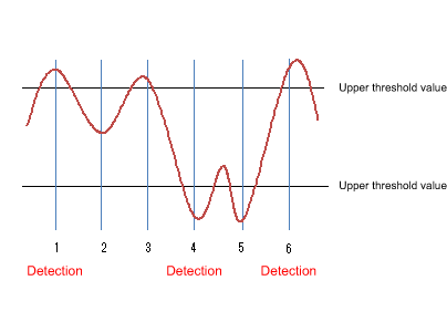
- At point 1, the upper threshold value is crossed, so an alarm is detected.
The threshold value that is used for the very first decision can be specified by STARTUP.
In the example above, we will assume that the STARTUP value is “1” (using only the upper threshold value (risingAlarm)) or “3” (using both the upper threshold value and the lower threshold value (risingOrFallingAlarm)).
- At point 2, an alarm is not detected.
- At point 3, the upper threshold value is crossed, but since the opposite threshold was not previously crossed, an alarm is not detected.
- At point 4, the lower threshold value is crossed, and since the upper threshold was previously crossed, an alarm is detected.
- At point 5, the lower threshold value is exceeded, but since the opposite upper threshold was not previously crossed, an alarm is not detected.
- At point 6, the upper threshold value is crossed, and since the lower threshold was previously crossed, an alarm is detected.
3.5 Event group
The operating specifications for the event group are shown below.
- Use the rmon event command to make settings.
- The following operations can be specified for the event group.
- Record to log
- Send SNMP trap
- Record to log and send SNMP trap
- If trap transmission is specified, the following SNMP commands must be set in order to transmit the SNMP trap.
- snmp-server host
- snmp-server enable trap rmon
- The following operations will be carried out when specifying trap transmission.
- SNMPv1, SNMPv2c
- Only the traps for which the community name specified using the rmon event command, and for which the community name specified by the snmp-server host host command are matching will be transmitted.
- SNMPv3
- Only the traps for which the community name specified using the rmon event command, and for which the user name specified by the snmp-server host host command are matching will be transmitted.
- Only the traps for which the community name specified using the rmon event command, and for which the user name specified by the snmp-server host host command are matching will be transmitted.
- SNMPv1, SNMPv2c
- The supported OIDs in the event group are as follows.
 rmon(1.3.6.1.2.1.16)
  +- event(1.3.6.1.2.1.16.9)
      +- eventTable(1.3.6.1.2.1.16.9.1)
              + eventEntry(1.3.6.1.2.1.16.9.1.1) { eventIndex }
                  +- eventIndex(1.3.6.1.2.1.16.9.1.1.1)        (read-only)
                  +- eventDescription(1.3.6.1.2.1.16.9.1.1.2)  (read-create)
                  |     Event description
                  +- eventType(1.3.6.1.2.1.16.9.1.1.3)         (read-create)
                  |     Event type
                  +- eventCommunity(1.3.6.1.2.1.16.9.1.1.4)    (read-create)
                  |     Community name
                  +- eventLastTimeSent(1.3.6.1.2.1.16.9.1.1.5) (read-only)
                  |     Event execution time
                  +- eventOwner(1.3.6.1.2.1.16.9.1.1.6)        (read-create)
                  |     Name of owner
                  +- eventStatus(1.3.6.1.2.1.16.9.1.1.7)       (read-create)
                        Event group status
3.6 Setting by SetRequest from an SNMP manager
The same content as the commands of each group can be specified by using SetRequest from an SNMP manager.
The procedure for making settings from an SNMP manager is as follows.
As an example, we explain how to make new settings for the Ethernet statistics information (etherStatsTable) group to port1.1 using index number 1.
Similar operations can be used to make settings for a supported MIB on other groups.
- Make SNMP settings to allow the MIB to be written.
For details, refer to the SNMP technical reference.
- For etherStatsStatus.1, specify “2” (createRequest).
The “.1” of etherStatsStatus.1 is the etherStatsTable index.
- For etherStatsDataSource.1, specify iFindex.5001 as the interface to be monitored.
ifIndex.5001 indicates port1.1.
- Specifying “owner” is optional, but if you do, specify the text string in etherStatsOwner.1.
- For etherStatsStatus, specify “1” (valid).
When you perform the above steps, the following commands are specified for port1.1.
We assume that “RMON” was set as the “owner” setting.
rmon statistics 1 owner RMON
Below we show how to disable the RMON function system-wide from the SNMP manager.
- Make SNMP settings to allow the MIB to be written.
For details, refer to the SNMP technical reference.
- For ysrmonSetting(1.3.6.1.4.1.1182.3.7.1), specify “2” (disabled).
When you perform the above steps, the following commands are specified.
rmon disable
To specify enable, set ysrmonSetting(1.3.6.1.4.1.1182.3.7.1) to “1” (enabled).
4 Related Commands
Related commands are shown below.
For details on the commands, refer to the Command Reference.
List of related commands
| Operations | Operating Commands |
|---|---|
| RMON function settings | rmon |
| Set RMON Ethernet statistical information group | rmon statistics |
| Set RMON history group | rmon history |
| Set RMON event group | rmon event |
| Set RMON alarm group | rmon alarm |
| Show RMON function status | show rmon |
| Show RMON Ethernet statistical information group status | show rmon statistics |
| Show RMON history group status | show rmon history |
| Show RMON event group status | show rmon event |
| Show RMON alarm group status | show rmon alarm |
| Clear RMON Ethernet statistical information group counters | rmon clear counters |
5 Examples of Command Execution
5.1 Set Ethernet statistical information group
Make Ethernet statistical information group settings for port 1.1, and from the SNMP manager, retrieve the MIB of the Ethernet statistical information group.
- Enable the Ethernet statistical information group setting for port1.1.
The index of the Ethernet statistical information group is “1.”
Yamaha(config)#interface port1.1
Yamaha(config-if)#rmon statistics 1 ... (Enable the Ethernet statistical information group setting)
- From the SNMP manager, make SNMP settings that the MIB of the Ethernet statistical information group can be retrieved.
In this example, we use “private” access on SNMPv1 or SNMPv2c.
Yamaha(config)#snmp-server community private rw ... (Set the readable/writable community name as “private”)
- From the SNMP manger, it will be possible to retrieve the etherStatsTable(.1.3.6.1.2.1.16.1.1) with the community name “private.”
5.2 Set history group
Make settings for the history group of port1.1 and retrieve the MIB of the history group from the SNMP manager.
- Enable the port1.1 history group setting.
The index of the history group is “1.”
Yamaha(config)#interface port1.1
Yamaha(config-if)#rmon history 1 ... (Enable the history group setting)
- From the SNMP manager, make SNMP settings that the MIB of the history group can be retrieved.
In this example, we use “private” access on SNMPv1 or SNMPv2c.
Yamaha(config)#snmp-server community private rw ... (Set the readable/writable community name as “private”)
- From the SNMP manger, it will be possible to retrieve the etherHistoryTable(.1.3.6.1.2.1.16.2.2) with the community name “private.”
5.3 Set alarm event group
Use the alarm group to monitor the statistical information values of the Ethernet statistical information group.
The conditions for monitoring are as follows.
- The MIB to be monitored is port1.1’s etherStatsPkts(.1.3.6.1.2.1.16.1.1.1.5).
- The sampling interval is 180 seconds.
- The sampling type is delta.
- The upper threshold value is 2000.
- The lower threshold value is 1000.
When the above monitoring conditions are matched, the following event group is executed.
- Record to log and send SNMP trap
- Community name is “RMON”
- Make the required settings for SNMP trap transmission.
Yamaha(config)#snmp-server host 192.168.100.3 traps version 2c RMON ... (Set trap transmission destination)
Yamaha(config)#snmp-server enable trap rmon                         ... (Enable trap transmission for the RMON function)
- Make event group settings.
The index of the event group is “1.”
Yamaha(config)#rmon event 1 log-trap RMON ... (Enable the event group setting)
- In order to set the alarm group’s monitoring target MIB object, enable the port1.1 Ethernet statistical information group setting.
The index of the Ethernet statistical information group is “1.”
Yamaha(config)#interface port1.1
Yamaha(config-if)#rmon statistics 1 ... (Enable the Ethernet statistical information group setting)
- Set the alarm group with the listed conditions.
The index of the alarm group is “1.”
Yamaha(config)#rmon alarm 1 etherStatsPkts.1 interval 180 delta rising-threshold 3000 event 1 falling-threshold 2000 event 1 ... (Enable the alarm group)
6 Points of Caution
None
7 Related Documentation
SYSLOG
1 Function Overview
This product provides the SYSLOG functions shown below as a means to ascertain the operating state.
- Functions to collect, reference, and delete the log that is accumulated inside this product
- Functions for output to the console simultaneously with logging
- Functions for transmitting to a previously-registered notification destination (SYSLOG server) simultaneously with logging
Logging, output to console, and notifications to the SYSLOG server are performed according to the output level specified by the user. Processing occurs only for the permitted messages.
Logging occurs in RAM, and is automatically backed up to flash ROM or can be backed up manually.
When backing up manually, you can also back up to an SD card at the same time.
Notifications to the SYSLOG server are done simultaneously with logging, but only if a SYSLOG server has been registered.
2 Definition of Terms Used
None
3 Function Details
The SYSLOG function is described below.
- Logging occurs in RAM, and can accumulate up to 10,000 items.
Backup to Flash ROM can be performed by the following means.
- Automatic backup performed every hour since system boot
- Manual backup performed by the save logging command
- Backup performed when the write command is executed successfully
- The accumulated log can be viewed by the show logging command.
It can also be deleted by the clear logging command.
The show logging command shows the information in RAM.
For the log information of this product, it is assumed that the information in RAM always matches the information in flash ROM.
(When the system starts, the log information in flash ROM is applied to RAM, and the service is started. The log information in RAM is not deleted following execution of a backup.)
- Log transmission occurs only if the notification destination (SYSLOG server) has been registered.
You can use the logging host command to register up to two notification destinations.
Specify the notification destination either by IP address or FQDN.
As the port number of the notification destination, the default port number 514 is used. (This setting cannot be freely set by the user.)
Logging facility values included in log notifications can be set using the logging facility command. The factory default setting is local0(16).
The logging format command can be used to change the format of log notifications to not include the header portion (time stamp and host name). The following are log examples.
- Without the format specified (no logging format)
<134>Jan 1 00:00:00 Yamaha [ IMI]:inf: Configuration file is saved in “config0”
- With the format specified (logging format legacy)
<134>[ IMI]:inf: Configuration file is saved in “config0”
- Without the format specified (no logging format)
- The level of log that is transmitted (SYSLOG priority) can be set using the logging trap command.
This product allows you to enable or disable output for each level of log.
With the factory settings, the output level enables only Information and Error.
- The logging backup sd command enables SYSLOG backup to the SD card.
If SYSLOG backup to the SD card is enabled, executing the save logging command will save the dated log file to the SD card.
4. List of related commands
Related commands are shown below.
For details, refer to the Command Reference.
List of related commands
| Function name | Command name |
|---|---|
| Set log output level | logging trap |
| Set log console output | logging stdout |
| Set log notification destination (SYSLOG server) | logging host |
| Changes the log notification format | logging format |
| Back up log | save logging |
| Clear log | clear logging |
| Show log | show logging |
| Set SD card backup of log | logging backup sd |
| Sets the logging facility value | logging facility |
5 Examples of Command Settings
- Enables debug-level log output and starts log output to the SYSLOG server (192.168.1.100) with a facility value of 10.
Yamaha(config)# logging trap debug         … (Enable debug level log output)
Yamaha(config)# logging facility 10        … (Sets the facility value to 10)
Yamaha(config)# logging host 192.168.1.100 … (Register SYSLOG server)
Yamaha(config)# logging stdout info        … (Output informational-level log to the console)
- Stop notifications to the SYSLOG server.
Yamaha(config)# no logging host
- Save and show the accumulated log information.
Yamaha# save logging … (Save log from RAM to ROM)
Yamaha# show logging … (Show accumulated log)
2018/03/08 20:42:46: [ SESSION]:inf: Login succeeded as (noname) for HTTP: 192.168.1.40
2018/03/09 10:06:42: [     NSM]:inf: Interface port1.11 changed state to down
2018/03/09 10:09:48: [ SESSION]:inf: Logout timer expired as (noname) from HTTP: 192.168.1.40
2018/03/09 16:19:36: [     NSM]:inf: Interface port1.17 changed state to up
 :
- Clear the accumulated log information.
Yamaha# clear logging … (Clear all accumulated logs)
Yamaha# show logging  … (Show log)
 (Since they were cleared, nothing is shown)
6 Points of Caution
None
7 Related Documentation
None
Firmware update
1 Function Overview
This product offers the following three firmware update functions, in order to correct problems in the program and to add new functionality.
- Firmware updates can be transmitted and applied to this product from a remote terminal such as a PC.
- This product’s built-in HTTP client can access an HTTP server, to download and apply the latest firmware.
- A firmware update placed on the SD card can be applied to this product.
These update functions can be used to upgrade or downgrade the version of firmware used on this product.
During firmware updating, all port LEDs flash green, regardless of the LED display mode setting.
When a stack is configured, the updated firmware is written simultaneously to the stack main and members switches.
When successfully finished writing the updated firmware, the system is automatically rebooted in order to apply the new firmware.
For instructions on how to specify rebooting the system, refer to 3.4 Reboot After Writing.
2 Definition of Terms Used
None
3 Function Details
3.1 Update by transmitting the firmware update
This function transmits firmware updates to this product from a remote terminal, such as a PC, and applies it as boot firmware.
The update process is executed using a TFTP client or the Web GUI.
3.1.1 Using a TFTP client to update the firmware
Firmware can be updated by using a TFTP client installed on a computer or other remote terminal to transmit the updated firmware to this device.
In order to operate this product’s TFTP server, use the steps shown below to set up a network environment that allows remote access.
- Decide on the VLAN that will be used for maintenance.
- Set the IPv4 address on the maintenance VLAN. Set it using the ip address command.
- Permit access from the maintenance VLAN to the TFTP server. Use the tftp-server interface command or the management interface command to specify that setting.
- Enable the TFTP server. Enable the server using the tftp-server enable command.
Follow the rules below when sending the firmware update using the TFTP client.
- Set the transmission mode to “binary mode”.
- As shown in the table below, specify the remote path to which the firmware update is sent.
- Specify the administrative password in the form “/PASSWORD” at the end of the remote path.
However, the firmware update cannot be applied if the administrative password is still set to the default setting. The administrative password setting must be changed in advance.
When updating firmware that uses TFTP clients, the following updates are possible.
Updated firmware
| Type | Remote path |
|---|---|
| Internal firmware | exec |
If there is no problem with the firmware update that was sent, the firmware update will be saved.
3.1.2 Updating the firmware by specifying a local file in the Web GUI
Specify the firmware update located on the terminal accessing the Web GUI, and applies it to this product.
This function does not do a version comparison with the existing firmware, and will overwrite the specified firmware regardless of version.
To update firmware by specifying a local file, click [Maintenance] - [Firmware update] in the Web GUI on the computer. (Refer to the part shown in a red frame on the screenshot below.)
Refer to the help contents within the GUI for the specific operation method.
Initial screen on the Web GUI for updating firmware using a PC
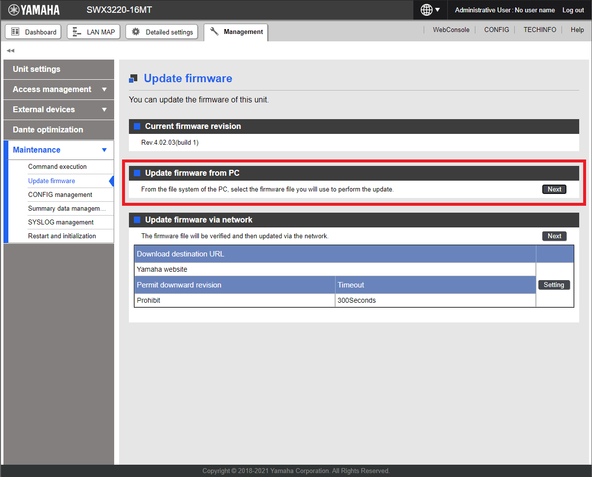
3.2 Using an HTTP client to update the firmware
This method of firmware update uses an HTTP client to obtain the firmware update from a specified URL, and then apply it to this product.
This function assumes that the firmware version will be upgraded. Downgrading to a previous version will only be permitted if “revision-down” is allowed.
The firmware cannot be rewritten with the same version of firmware.
An HTTP client can be used to update the firmware using the methods below.
- Use the firmware-update command in the CLI (command-line interface).
- Execute update firmware via the network in the Web GUI.
Updating the firmware with an HTTP client is done by using the settings value shown in the table below.
Firmware update using an HTTP client: setting parameters
| Setting parameter | Explanation |
|---|---|
| Download source URL | Sets the source URL from which the firmware is downloaded. A URL of up to 255 characters in length can be set. The URL must be entered in the form “http://<server IPv4/IPv6 address or host name>/<path name>”. If an IPv6 address is specified, it must be enclosed in square brackets. For server port numbers other than 80, the port number must be specified within the URL address, in the form “http://server IP address or host name:port number/path name.” The initial value is set as follows for each model. http://www.rtpro.yamaha.co.jp/firmware/revision-up/swx3220.bin http://www.rtpro.yamaha.co.jp/firmware/revision-up/swx2320.bin http://www.rtpro.yamaha.co.jp/firmware/revision-up/swx2322p.bin |
| Proxy Server URL | Specifies the proxy server to use for updating firmware. Specify it either as an IPv4/IPv6 address or FQDN. FQDNs can be up to 255 characters long. No proxy server is specified in default settings. Proxy servers must be specified as an IPv4/IPv6 address or in the form “http://<host name>/<path name port number>.” If an IPv6 address is specified, it must be enclosed in square brackets. |
| Permit downward revision | Sets whether the current version of firmware can be downgraded to a previous version. The default value is “Don’t allow”. Overwriting the firmware with the same version of firmware is not permitted. |
| Timeout | Specifies the timer for monitoring the completion of the processes shown below. ・ Check whether firmware version is new/old. ・ Download it from the designated URL. The monitoring timer can be set from 100 seconds to 86,400 seconds, but the default setting is 300 seconds. |
For instructions on using the firmware-update command, refer to “5 Examples of Command Execution” or the “Command Reference”.
To update firmware over the network using the Web GUI, execute [Maintenance] - [Firmware update] on the Web GUI. (Refer to the part shown in a red frame on the screenshot below.)
Refer to the help contents within the GUI for the specific operation method.
Initial Web GUI Screen for Updating Firmware via the Network
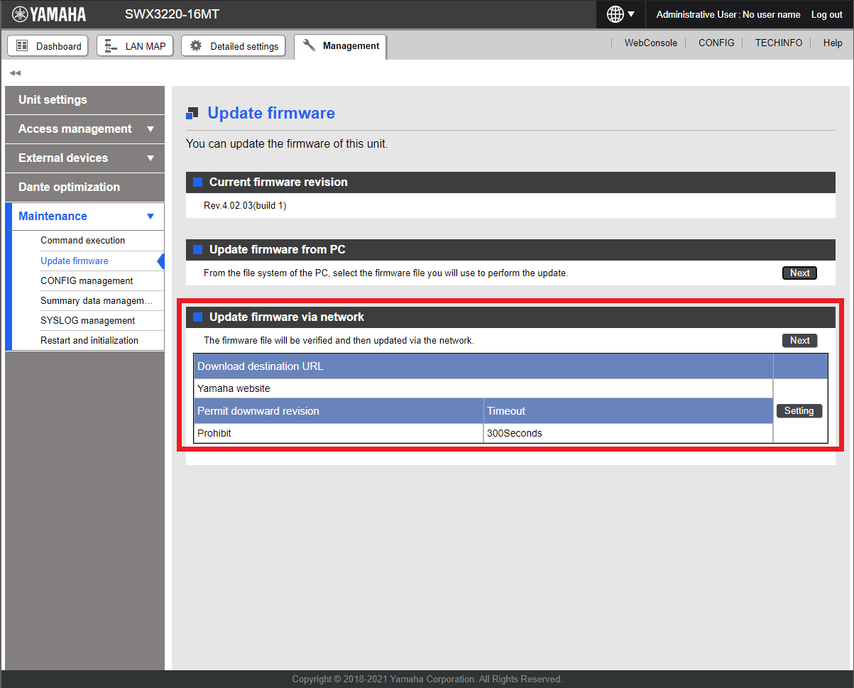
3.3 Using an SD card to update the firmware
This function takes a firmware update from the SD card and applies it as boot firmware.
For this update method, execute the firmware-update sd execute command in the CLI (command-line interface).
If a stack was configured, commands can only be executed from the main switch in the stack.
After entering the firmware update confirmation, the update will continue even if the SD card is removed. To unmount the SD card when executing the command, enter “n” when prompted to confirm whether to maintain the SD card mount status or specify the “sd-unmount” command option.
If the system is rebooted with the SD card inserted in the main unit, the system will be booted using the firmware in the SD card, as specified by the boot prioritize sd command.
- File path in the SD card
/swx3220/firmware/swx3220.bin
/swx2320/firmware/swx2320.bin
/swx2322p/firmware/swx2322p.bin
3.4 Reboot after writing
When successfully finished writing the firmware update, the system is automatically rebooted.
However, the system is not rebooted if the “no-reboot” option is specified for firmware-update execute or firmware-update sd execute commands.
If the firmware-update reload-time command is specified without specifying the “no-reboot” option, then the system is rebooted according to the reboot time setting.
The revision after the next reboot can be confirmed by executing the show firmware-update command.
If a stack is configured, the firmware update method can be selected using the firmware-update reload-method command.
- Method to update member switches during configuration simultaneously
- Method to update without stopping network services
For an overview of actions for firmware update methods, see Stack function.
4 Related Commands
Related commands are shown below.
For details, refer to the Command Reference.
List of related commands
| Operations | Operating commands |
|---|---|
| Set firmware update site | firmware-update url |
| Set proxy server | firmware-update http-proxy |
| Execute firmware update | firmware-update execute |
| Set firmware download timeout duration | firmware-update timeout |
| Permit downward revision | firmware-update revision-down |
| Show firmware update function settings | show firmware-update |
| Execute firmware update from SD card | firmware-update sd execute |
| Set firmware update reboot time | firmware-update reload-time |
| Setting the firmware update restart method during stack configuration | firmware-update reload-method |
5 Examples of Command Execution
5.1 Using an HTTP client to update the firmware
In this example, the firmware update is stored on the local HTTP server, and this product is set to manage the firmware in order to perform the update.
- Changes the firmware download URL to http://192.168.100.1/swx3220.bin .
- Leaves the proxy server setting blank.
- The downward revision setting is left disabled.
- The timeout value is left at 300 sec.
- A reboot time is not specified, but the system is rebooted immediately after updates.
- The download URL is changed, and the firmware update settings are confirmed.
Yamaha(config)#firmware-update url http://192.168.100.1/swx3220.bin … (Sets the download destination URL) Yamaha(config)#exit Yamaha#show firmware-update … (Shows the firmware update function setting) url: http://192.168.100.1/swx3220.bin http-proxy: - timeout: 300 (seconds) revision-down: Disable firmware revision for next boot: - reload-time: - reload-method: Normal - The firmware update is executed.
Yamaha#firmware-update execute … (Executes firmware update) Found the new revision firmware Current Revision: Rev.4.02.01 New Revision: Rev.4.02.03 Downloading... Update to this firmware? (y/n)y … (Enters y value) Updating... Finish (Reboots automatically) - Pressing “CTRL+C” during the firmware update process will interrupt the update.
    Yamaha#firmware-update execute
    Found the new revision firmware
    Current Revision: Rev.4.02.01
    New Revision:     Rev.4.02.03
    Downloading...                  … (“Ctrl-C” entered)
    ^CCanceled the firmware download
5.2 Using an HTTP client to update the firmware (in a proxy server environment)
This updates the firmware by specifying a proxy server.
- The initial download URL setting is left unchanged.
- The proxy server is set to http://192.168.100.1:8080.
- The downward revision setting is left disabled.
- The timeout value is left at 300 sec.
- A reboot time is not specified, but the system is rebooted immediately after updates.
- Specify the HTTP proxy settings and confirm the firmware update settings.
Yamaha(config)#firmware-update http-proxy http://192.168.100.1 8080 … (Sets the HTTP proxy server) Yamaha(config)#exit Yamaha#show firmware-update … (Shows firmware update function settings) url: http://www.rtpro.yamaha.co.jp/firmware/revision-up/swx3220.bin http-proxy: http://192.168.100.1:8080 timeout: 300 (seconds) revision-down: Disable firmware revision for next boot: - reload-time: - reload-method: Normal - The firmware update is executed.
    Yamaha#firmware-update execute … (Executes firmware update)
    Found the new revision firmware
    Current Revision: Rev.2.04.01
    New Revision:     Rev.2.04.02
    Downloading...
    Update to this firmware? (y/n)y … (Enters y value)
    Updating...
    Finish

    (Reboots automatically)
5.3 Using an SD card to update the firmware
In this example, the firmware update is placed on an SD card inserted in the unit, and this product is set to manage the firmware in order to perform the update.
This is an example of a two-stack configuration.
- Changes the reboot time to 23:30.
- Changes the reboot method to rebooting the stack main switch and then successively rebooting member switches.
- Change the reboot time and reboot method.
Yamaha(config)#firmware-update reload-time 23 30 … (Changes the reboot time setting) Yamaha(config)#firmware-update reload-method sequential … (Sets the reboot method) Yamaha(config)#exit - Insert the SD card into the main switch in the stack and execute the firmware update.
Yamaha#firmware-update sd execute … (Executes firmware update) Update the firmware. Current Revision: Rev.4.02.01 New Revision: Rev.4.02.03 Update to this firmware? (y/n)y … (Enters y value) Continue without unmounting the SD card? (y/n)n … (Enters n value) Unmounted the SD card. Pull out the SD card. Updating... Finish Yamaha# (Reboots at the specified reboot time) - The stack member firmware is updated at the same time as the stack main switch, but the members are rebooted after the firmware in the stack main switch has been rebooted.
The following log history is displayed on stack member consoles.
(The firmware update is received and the update is started after pressing ENTER on the stack main switch.) Receiving exec file... Testing received file... Writing to Nonvolatile memory... Done. (Reboots the device at the specified reboot time.) - After checking the version of the update firmware, you can enter “n” to cancel.
    Yamaha#firmware-update sd execute  … (Executes the firmware update)
    Update the firmware.
    Current Revision: Rev.4.02.01
    New Revision:     Rev.4.02.03

    Update to this firmware? (y/n)n … (Enters n value)
    Yamaha#
6 Points of Caution
If the system is rebooted or the power is turned off during firmware update, the update will be interrupted and the system will start with the firmware before the update operation.
7 Related Documentation
L2MS control
1 Function Overview
L2MS (Layer2 Management Service) is functionality for managing Yamaha network devices at the layer 2 level.
L2MS is configured with one L2MS manager unit (referred to as “manager” below) that manages multiple L2MS agent units (referred to as “agents” below).
Devices can be used as either a manager or agent.
The following illustrates how to connect the computer, manager, and agents.
L2MS Connections

Connect the computer to the manager via a serial connection or log in via Telnet or HTTP/HTTPS.
The manager includes commands for managing the agents and a Web GUI for specifying the settings or checking the status of agents. These can be used to operate the agents.
The manager is connected to agents via Ethernet cables and uses a proprietary protocol (L2MS) for communication.
This functionality has the following characteristics.
- Initial settings are not required
Although IP addresses must be specified if using Telnet or SSH, default settings do not need to be specified for agents, because the functionality uses a proprietary protocol (L2MS) for communication.
When Ethernet cables are connected, the manager automatically detects subordinate agents.
- Multiple supported devices can be controlled simultaneously
The manager can recognize and control multiple agents simultaneously.
The proprietary communication protocol used by L2MS is the same protocol as used for communication by the switch control functionality supported by Yamaha routers and SWX series and WLX series.
That means both SWX series and WLX series devices can be managed from the manager.
2 Definition of Terms Used
Manager
A manager is a device that manages Yamaha network devices functioning as an agent based on L2MS and switch control functionality.
It manages Yamaha switches and Yamaha wireless apps within the network.
Agent
A Yamaha switch or Yamaha wireless AP that is managed by a manager based on L2MS and switch control functionality.
Settings can be checked or changed from the manager.
3 Function Details
3.1 Supported models
Devices can be used as either an L2MS manager or agent.
If operating as a manager, each manager can control a maximum of 128 agent units.
The following models can be managed as an agent.
As described earlier, any device that supports switch control functionality (agents) can also be controlled.
- SWX2100 series (SWX2100-8G, SWX2100-16G, SWX2100-24G, SWX2100-5PoE, SWX2100-10PoE)
- SWX2110 series (SWX2110-5G, SWX2110-8G, SWX2110-16G)
- SWX2110P series (SWX2110P-8G)
- SWX2200 series (SWX2200-8G, SWX2200-24G, SWX2200-8PoE)
- SWX2210 series (SWX2210-8G, SWX2210-16G, SWX2210-24G)
- SWX2210P series (SWX2210P-10G, SWX2210P-18G, SWX2210P-28G)
- SWX2220 series (SWX2220-10NT)
- SWX2221P series (SWX2221P-10NT)
- SWX2300 series (SWX2300-8G, SWX2300-16G, SWX2300-24G)
- SWX2310 series (SWX2310-10G, SWX2310-18GT, SWX2310-28GT, SWX2310-52GT)
- SWX2310P series (SWX2310P-10G, SWX2310P-18G, SWX2310P-28GT)
- SWX2320 series (SWX2320-16MT)
- SWX2322P series (SWX2322P-16MT)
- SWX3100 series (SWX3100-10G, SWX3100-18GT)
- SWX3200 series (SWX3200-28GT, SWX3200-52GT)
- SWX3220 series (SWX3220-16MT, SWX3220-16TMs)
- WLX series (WLX202, WLX212, WLX222, WLX302, WLX313, WLX402, WLX413)
If operated as an agent, the unit is managed by the Yamaha router or Yamaha switch manager.
For details about compatible Yamaha router models, refer to Switch control functionality of Yamaha routers.
3.2 Usage
The L2MS operation and role is set by the l2ms command.
- L2MS Managers
L2MS managers manage the SWX and WLX series switches operating as agents.
The terminal-watch enable command can be used to periodically acquire and monitor information about computers and other terminals present in the network.
Yamaha(config)#l2ms configuration
Yamaha(config-l2ms)#l2ms enable
Yamaha(config-l2ms)#l2ms role manager
Yamaha(config-l2ms)#terminal-watch enable
- L2MS Agents
L2MS agents are managed by a Yamaha router or Yamaha switch operating as a manager.
Yamaha(config)#l2ms configuration
Yamaha(config-l2ms)#l2ms enable
Yamaha(config-l2ms)#l2ms role agent
The show l2ms command can be used to check an agent’s current action and role.
3.3 L2MS Protocol
L2MS control is performed using the proprietary protocol L2 frames indicated below.
Content of L2MS Protocol L2 Frames
| Item | Value |
|---|---|
| Destination MAC | 01:a0:de:00:e8:12 to 01:a0:de:00:e8:15 |
| Ether Type | 0xe812, 0xe813 |
If a firewall is specified between the manager and agents, the firewall settings must allow these L2 frames to pass through.
3.4 Monitoring agents
Managers monitor subordinate agents by sending query frames at regular intervals.
Agents respond to query frames by sending a response frame to notify the manager that they exist.
The interval between sending query frames is specified using the agent-watch interval command.
Increasing the setting value will decrease the sending frequency, but will lengthen the time for the manager to recognize an agent after it is contacted.
Decreasing the setting value will, conversely, increase the sending frequency, but shorten the time for the manager to recognize an agent after it is contacted.
If the manager does not receive a response frame from an agent after sending the specified number of query frames, the manager will decide that the corresponding agent has gone down.
The number of attempts is specified by the agent-watch down-count command.
If the Ethernet cable connected to the agent is disconnected, in some cases the manager might decide that the agent has gone down sooner than specified by the command.
Specify appropriate setting values for agent-watch interval and agent-watch down-count commands based on the given network environment being used.
3.5 Agent ownership
No agent may be simultaneously controlled by multiple managers.
Therefore, only specify one manager per network.
If an agent receives a query frame after rebooting, that agent will be managed by the manager that sent the query frame.
That relationship is canceled if any of the following occur.
- A query frame is not received for 30 seconds.
- The manager is rebooted.
- The l2ms reset command is executed by the manager.
3.6 Agent Operations
If a manager sets a setting for an L2MS-compliant agent or checks its operating status, such actions are referred to as “operating the agent”.
Agents are operated using the LAN map on the Web GUI.
To operate an agent, log into the manager Web GUI and select the applicable agent in the LAN map.
For more detailed LAN map operating instructions, refer to the Web GUI help page.
Note that agents cannot be operated using commands executed by the manager.
The following describes how to operate each operable agent via the LAN map.
3.6.1 Controlling SWX2100 Series Units
The following operations can be performed for agents.
- Display the status of the device and ports
- Show and control the power supply status of ports (PoE-equipped models only)
- Show/maintain switch settings (show function settings, update firmware, restart, etc.)
3.6.2 Controlling SWX2110, SWX2110P Series Units
The following operations can be performed for agents.
- Display the status of devices and ports
- Show and control the power supply status of ports (PoE-equipped models only)
- Set/maintain switch settings (change function settings, update firmware, reboot, etc.)
- Specify ports (VLAN tags, etc.)
- Save and restore config settings
3.6.3 Controlling SWX2200 Series Units
The following operations can be performed for agents.
- Display the status of devices and ports
- Show and control the power supply status of ports (PoE-equipped models only)
- Set/maintain switch settings (change function settings, update firmware, reboot, etc.)
- Save settings to the manager and synchronize settings with settings saved in the manager
If SWX2200 settings are set from the manager, the settings are saved in both the manager and SWX2200 unit.
The settings are saved as a separate file from the manager config file, but the startup-config select command can be used to change the config settings at the same time.
If the SWX2200 unit is managed by the manager, settings in the manager and SWX2200 unit will be kept synchronized.
For details on synchronization of settings, refer to “3.6.7 Synchronizing Settings”.
The status of settings in SWX2200 units managed by the manager can be checked using the show l2ms agent-config command.
3.6.4 Operations for SWR2210, SWX2210P, SWX2220, and SWX2221P Series Agents
The following operations can be performed for agents.
- Display the status of devices and ports
- Show and control the power supply status of ports (PoE-equipped models only)
- Change settings and perform maintenance (changing function settings, rebooting, etc.)
- Specify port settings (tagged VLAN, multiple VLANs, etc.)
- Specify link aggregation
- Change the IP address setting
- Save and restore config settings
- Use HTTP proxy functionality to log into the agent GUI
- Find this switch (SWX2220/SWX2221P models only)
If the HTTP proxy functionality is enabled, then it is possible to log into agent GUIs from the manager LAN map.
That eliminates the need to enter a username and password for logging into an agent.
If SWX2210, SWX2210P, SWX2220, or SWX2221P series units are managed by a manager configured with factory settings, then DHCP client settings are specified automatically.
For more details, refer to “3.6.8. HTTP Proxy Function and Setting IP Addresses”.
・ The SWX2210 model supports Rev.1.02.10 and later firmware.
・ The SWX2210P model supports Rev.1.03.08 and later firmware.
3.6.5 Controlling SWX2300, SWX2310, SWX2310P, SWX2320, SWX2322P, SWX3100, SWX3200, or SWX3220 Series Units
The following operations can be performed for agents.
- Display the status of the device and ports
- Show and control the power supply status of ports (PoE-equipped models only)
- Change the IP address setting
- Saving and restoring config settings
*Saving and restoring SWX2300 config settings is supported by Rev. 2.00.14 and later firmware. - Use HTTP proxy functionality to log into the agent GUI.
If the HTTP proxy functionality is enabled, then it is possible to log into agent GUIs from the manager LAN map.
That eliminates the need to enter a username and password for logging into an agent.
If SWX2300, SWX2310, SWX2310P, SWX2320, SWX2322P, SWX3100, SWX3200, or SWX3220 series units are managed by a manager configured with factory settings, then DHCP client settings are specified automatically.
For more details, refer to “3.6.8. HTTP Proxy Function and Setting IP Addresses.”
3.6.6 Controlling WLX Series Units
The following operations can be performed for agents.
- Display the status of devices, LAN ports, and wireless modules
- Change the IP address setting
- Save and restore config settings
- Use HTTP proxy functionality to log into the agent GUI
If the HTTP proxy functionality is enabled, then it is possible to log into agent GUIs from the manager LAN map.
That eliminates the need to enter a username and password for logging into an agent.
If a WLX series unit is managed by a manager configured with factory settings, then DHCP client settings are specified automatically.
For more details, refer to “3.6.8. HTTP Proxy Function and Setting IP Addresses”.
3.6.7 Synchronizing Settings
If an SWX2200 unit is managed by a manager, then settings held in the manager and SWX2200 unit are kept synchronized.
Synchronization is unidirectional from the manager to the SWX2200 unit, with the SWX2200 unit always operating based on settings in the manager.
When the manager starts managing an SWX2200 unit, it first checks whether the manager and SWX2200 settings match.
If they do not match, the following processes are performed.
- All SWX2200 settings are restored to default values.
- Function setting values held by the manager are sent to the SWX2200 unit.
The manager periodically monitors the settings of subordinate SWX2200 units and synchronizes them if a discrepancy is detected.
Synchronization may take some time (several tens of seconds to several minutes).
During synchronization, other SWX2200 operations are disabled.
Attempting to specify settings will cause an error without applying the settings to the manager or SWX2200 unit.
3.6.8 HTTP Proxy Function and Setting IP Addresses
The following actions are performed for SWX2300, SWX2310, SWX2310P, SWX2320, SWX2322P, SWX3100, SWX3200, SWX3220 series, or WLX series series units.
Given factory settings, a fixed IP address is specified immediately after executing the cold start command. (The L2MS operates as an agent.)
If the agent is managed by the manager, then DHCP client settings are specified automatically.
This is to avoid duplicate IP addresses if multiple agents exist.
Since IP addresses are assigned by the DHCP server within the network, agent Web GUIs can be accessed via the HTTP proxy server. However, that requires specifying the http-server enable setting in the agent.
If a DHCP server does not exist in the network, then IP addresses cannot be obtained and agent IP addresses must be specified on the manager LAN map.
Once the IP setting is specified and the startup config has been saved, it will not be automatically specified in the DHCP client thereafter.
3.7 Information Notifications from Agents
If an agent managed by a manager detects a change or error in its own status, it sends information to notify the manager.
Information sent from the agent is output in the manager SYSLOG or LAN map.
For details on messages output to the SYSLOG, refer to “7. SYSLOG Message List.”
The following information is included in notifications from agents.
Information in Notifications from Each Agent to the Manager
| Agent | Information sent |
|---|---|
| SWX2100 series | Port link up/down Loop detection SFP optical input level error (SWX2100-24G) Power supply function status for each port (PoE-equipped models only) Power supply function error for each device (PoE-equipped models only) |
| SWX2110 series SWX2110P series | Port link up/down Loop detection Power supply function status for each port (PoE-equipped models only) Power supply function error for each device (PoE-equipped models only) |
| SWX2200 series SWX2210 series SWX2210P series SWX2220 series SWX2221P series | Port link up/down Loop detection Fan error stop (SWX2200-24G, SWX2200-8PoE, SWX2210P, SWX2221P) Power supply function status for each port (PoE-equipped models only) Power supply function error for each device (PoE-equipped models only) Terminal monitoring status (SWX2220, SWX2221P) |
| SWX2300 series | Port link up/down Loop detection SFP optical input level error Sending queue usage rate error |
| SWX2310 series SWX2310P series SWX2320 series SWX2322P series SWX3100 series SWX3200 series SWX3220 series | Port link up/down Stack port link up/down (stack-compatible models only) Loop detection SFP optical input level error Sending queue usage rate error Power supply function status for each port (PoE-equipped models only) Power supply function error for each device (PoE-equipped models only) Temperature error (SWX2310-52GT, SWX2310P, SWX3200, SWX2320, SWX2322P, SWX3220) Fan error (SWX2310-52GT, SWX2310P, SWX3200, SWX2320, SWX2322P, SWX3220) Power supply error (SWX3200) Temperature sensor error (SWX2310P) Terminal monitoring status (operating or down) L2MS manager duplication |
| WLX series | Change in settings of the wireless function |
3.8 Monitoring Connected Terminals
Specifying the terminal-watch enable command in the manager enables functionality for monitoring connected terminals, so that information about terminals connected to the manager and agents can be managed.
The manager manages the following information about connected terminals.
- If the Manager and Agents are Yamaha Switches
- MAC address of the terminal
- Manager or agent port number to which the terminal is connected
- Date/time when terminal was detected
- If the Agent is a Yamaha Wireless AP
- MAC address of the terminal
- SSID to which the terminal is connected
- Frequency (2.4 or 5 GHz) of terminal connection
- Date/time when terminal was detected
This information can be viewed using the show l2ms detail command.
The recommended maximum number of terminals managed by this function is 200 units, regardless of network configuration.
Note that more than the recommended number of units in the network could cause LAN map actions on the Web GUI to be sluggish or unresponsive.
The manager will search for connected terminals or delete managed terminal information based on changes in the network.
The target and timing of manager searches for connected terminals are indicated below.
If new terminal information is found as a result of the search, it is determined that a terminal was detected.
Timing and Object of Terminal Searches
| Timing | Object |
|---|---|
| When the manager port is linked up | Corresponding port on the manager |
| When a new agent is detected | All ports on the detected agent |
| When link-up notification is received from a managed agent | Corresponding port on the agent |
| When the time specified by the terminal-watch interval command elapses | The manager and all agents |
The following indicates what managed terminal information is deleted and when it is deleted if the manager determines that the terminal has disappeared from a network.
Terminal for Which Information is Deleted and Deletion Timing
| Timing | Terminal |
|---|---|
| When the manager port is linked down | Terminal connected to the corresponding manager port |
| When an agent is detected to be down | All terminals connected to that agent |
| When a port link-down notification is received from a managed agent | Terminal connected to the corresponding agent port |
| When a previously-detected terminal is not found in connected terminal search | Terminals not found |
4 Related Commands
Related commands are indicated below.
For details, refer to the Command Reference.
List of L2MS-related commands
| Operations | Operating Command |
|---|---|
| Switch to L2MS mode | l2ms configuration |
| Enable L2MS function | l2ms enable |
| Set role of L2MS function | l2ms role |
| Set agent monitoring interval | agent-watch interval |
| Set number of times for deciding agent is down | agent-watch down-count |
| Enable terminal management function | terminal-watch enable |
| Set terminal information acquisition interval | terminal-watch interval |
| Set terminal information acquisition interval for terminals below wireless AP | wireless-terminal-watch interval |
| Enable event monitoring function | event-watch enable |
| Set event information acquisition interval | event-watch interval |
| Enable sending/receiving L2MS control frames | l2ms filter enable |
| Set whether to use agent zero-config function | config-auto-set enable |
| Reset agent management | l2ms reset |
| Show L2MS information | show l2ms |
| Show L2MS agent configuration information | show l2ms agent-config |
| Enable snapshot function | snapshot enable |
| Include/remove terminal for snapshot comparison | snapshot trap terminal |
| Create snapshot | snapshot save |
| Delete snapshot | snapshot delete |
| Set LAN map log output | logging event lan-map |
5 Examples of Command Execution
5.1 Agent monitoring settings
Set the time interval for monitoring agents.
Yamaha(config)#l2ms configuration
Yamaha(config-l2ms)#agent-watch interval 8
Set the number of monitoring times before deciding an agent is down.
Yamaha(config)#l2ms configuration
Yamaha(config-l2ms)#agent-watch down-count 7
5.2 Specifying Terminal Management Function Settings
Enable the terminal monitoring function.
Yamaha(config)#l2ms configuration
Yamaha(config-l2ms)#terminal-watch enable
Set the time interval for acquiring terminal information.
Yamaha(config)#l2ms configuration
Yamaha(config-l2ms)#terminal-watch interval 3600
Show the terminal information obtained by the manager.
Yamaha>show l2ms detail
Role : Manager

[Manager]
 Number of Terminals   : 0

[Agent]
 Number of Agents      : 2
  [ac44.f230.00a5]
   Model name          : SWX2100-24G
   Device name         : SWX2100-24G_Z5301050WX
   Route               : port2.1
   LinkUp              : 1, 3, 9
     Uplink            : 1
     Downlink          : 3
   Config              : None
   Appear time         : Tue Mar 13 18:43:18 2018
   Number of Terminals : 1
    [bcae.c5a4.7fb3]
     Port              : 9
     Appear time       : Wed Mar 14 14:01:18 2018

  [00a0.deae.b8bf]
   Model name          : SWX2300-24G
   Device name         : SWX2300-24G_S4L000401
   Route               : port2.1-3
   LinkUp              : 1
     Uplink            : 1
     Downlink          : None
   Config              : None
   Appear time         : Tue Mar 13 18:43:18 2018
   Number of Terminals : 0
5.3 Enabling/Disabling Sending/Receiving L2MS Control Frames
Disable sending or receiving L2MS control frames at port 1.5.
Yamaha(config)#interface port1.5
Yamaha(config-if)#l2ms filter enable
5.4 Enabling/Disabling the Event Monitoring Function
Disable the event monitoring function.
Yamaha(config)#l2ms configuration
Yamaha(config-l2ms)#event-watch disable
Set the time interval between acquiring event information.
Yamaha(config)#l2ms configuration
Yamaha(config-l2ms)#event-watch interval 60
5.5 Enabling/Disabling the Zero-Config Function
This specifies whether the manager uses the zero-config function for agents.
This setting must be specified in the manager.
Disable the zero config function.
Yamaha(config)#l2ms configuration
Yamaha(config-l2ms)#l2ms enable
Yamaha(config-l2ms)#l2ms role manager
Yamaha(config-l2ms)#config-auto-set disable
6 Points of Caution
6.1 Device Configuration
A maximum of 128 agents can be managed.
If the agents are used connected in series, a maximum of 8 agents can be connected from the manager.
Nine or more agents cannot be connected to the manager in series.
If up to 8 agents are connected in series from the manager, then the specified maximum number of managed agents can be controlled.
Connecting nine or more agents in series from the manager could prevent properly recognizing or controlling agents due to delays in L2MS communication or cause the following types of problems.
- The synchronization process might not function correctly.
- If agent settings are modified from the GUI, correct execution might not be possible.
If a non-Yamaha switch exists in the L2MS communication route, such as between the manager and an agent, it might not be possible to control the agent correctly.
If you are configuring a network that includes a non-Yamaha switch, verify its operation beforehand.
6.2 Terminal Monitoring
The recommended maximum number of managed units in a network is 200 units.
Including more than the recommended maximum number of managed units could cause the LAN map in the Web GUI to become sluggish or unresponsive.
If necessary, disable the terminal management function (terminal-watch disable command).
Terminal searches use the information registered in the FDB (MAC address table) for the applicable devices.
Therefore, depending on when the search is performed, a connected terminal might not be detected or a terminal no longer in the network might be detected.
If a link is detected to be down for a manager or Yamaha switch port, all information for the terminal connected to that port is deleted even if the terminal is registered in the FDB (MAC address table).
It may take L2MS several seconds to recognize an agent after it is connected to a port.
During that time, the corresponding agent is treated as a terminal.
Yamaha network devices that are not managed as an agent by the manager are treated as terminals.
Terminal searches performed at intervals specified by the terminal-watch interval command search for terminals connected to the manager or all agents, which might take twenty to thirty minutes to complete for some network configurations.
However, other processes are not disabled until terminal searches are completed.
If a non-Yamaha L2 switch is connected to an L2MS-compliant device, the terminals connected to the non-Yamaha L2 switch are detected as terminals connected to the L2MS-compliant device.
However, if a terminal and a Yamaha switch are connected in parallel to a non-Yamaha L2 switch, the terminal connected to the non-Yamaha L2 switch cannot be detected.
6.3 Use in Conjunction with Other Functionality
6.3.1 Use in Conjunction with a VLAN
If using a VLAN, ports used for L2MS communication must be specified as an access port or as a trunk port assigned by the native VLAN.
L2MS communication is not possible via a trunk port not assigned by the native VLAN.
6.3.2 Use in Conjunction with Mirroring
If the mirroring function is used, L2MS communications sent and received at the monitor port are also copied.
Therefore, L2MS might not function properly if the manager or an agent is connected to a mirror port, so do not connect a manager or an agent to a mirror port.
6.3.3 Use in Conjunction with ACL
L2MS communication is not subject to ACL control.
Although the ACL discards frames that are not specified in the permissions list (tacit rejection), L2MS communications are not subject to ACL control, so frames are forwarded without being discarded.
6.3.4 Use in Conjunction with STP or Loop Detection Functionality
L2MS communication is not possible on ports blocked by STP or loop detection functionality.
Link switching by STP could prevent the manager from recognizing the topology correctly, which could prevent finding agents or cause routing errors when agents are found.
In such cases, reset agent management after STP has finished switching the link by executing the l2ms reset command.
If multiple MST instances are operating, L2MS control frames are sent and received on the logical route (tree) formed by CIST (instance #0).
6.3.5 Use in Conjunction with Link Aggregation
If link aggregation is used, L2MS communication is considered to be occurring on “the lowest-numbered linked-up port associated with the logical interface.”
If link aggregation is used in conjunction with the monitoring function for connected terminals and a terminal is discovered at the end of a logical interface connection, then the terminal is considered to be connected to “the lowest-numbered linked-up port associated with the logical interface” and the corresponding port number is shown.
In Configuration 1, L2MS communication is assumed to be occurring between respective ports 1.1.
In Configuration 2, L2MS communication is assumed to be occurring between manager port 1.1 and agent port 1.1.

6.3.6 Use in Conjunction with the Stack Function
L2MS functions if even one unit is operating.
Even if the stack function is enabled, it is operated as one standalone unit if it cannot negotiate with a member switch.
L2MS will function even in that case.
- The L2MS manager can detect L2MS agents.
- L2MS agents are detected by the L2MS manager.
However, only devices connected below the standalone switch are detected, while not detecting devices connected to other switches assumed to be down.
7. SYSLOG Message List
L2MS outputs the following SYSLOG messages.
Output messages are appended with the "[ L2MS]” prefix.
SYSLOG messages displayed for units functioning as a manager are also appended with the "route (addr):” prefix.
“route” refers to the route and “addr” the agent MAC address (indicated in all lowercase, in the form “xxxx.xxxx.xxxx”).
SYSLOG Messages Displayed When the Unit Starts Up or the Operating Mode is Changed
| Type | Output Level | Message | Meaning |
|---|---|---|---|
| Operating Mode | informational | Start L2MS (manager) | The L2MS unit was started as the manager. |
| Start L2MS (agent) | The L2MS unit was started as an agent. | ||
| L2MS is disabled | The L2MS did not start because it was disabled in settings. | ||
| L2MS mode change mode_from to mode_to | The operating mode is changed from mode_from to mode_to. |
SYSLOG Messages Displayed When Operating as the Manager
| Type | Output Level | Message | Meaning |
|---|---|---|---|
| Agent Management | informational | Find agent | An agent was detected. |
| Detect down | An agent is down. | ||
| Synchronization Process | informational | Sync start | Agent synchronization process was started. |
| Sync done | Agent synchronization process is finished. | ||
| Sync failed | Agent synchronization process failed. | ||
| debug | Can’t get param of sync | Failed to obtain the agent information needed for synchronization process. | |
| Config Management | informational | Received config (file) | The manager received and saved the config file (file) from the agent. |
| Sent config (file) | The manager sent the config file (file) to the agent. | ||
| Removed config (file) | The config file (file) was deleted. | ||
| Terminal Management | debug | Update device info | Terminal information for the terminal connected to the agent was updated. |
| Fail to update device info | Failed to update terminal information for the terminal connected to the agent. | ||
| Terminal Information Database Management | debug | path : Format Version: Not found. | The format version is not indicated in the terminal information database file path. |
| path : Format Version: Illegal value. | An invalid value is included in the format version indicated in the terminal information database file path. | ||
| path : Device Information: Illegal value. (line) | An invalid value is indicated in the terminal information database file path (in the “line” line). | ||
| path : Device Information: Duplicate device. (line) | A conflicting device is indicated in device information in the terminal information database file path (in the “line” line). | ||
| path : Character Code: Not Shift_JIS. | Non-Shift JIS characters are included in the character string code in the terminal information database file path. | ||
| Manager Duplication | informational | L2MS manager duplication detected. (addr, port X) | A duplicate L2MS manager was detected. (MAC address, port number where duplication was detected) |
| L2MS manager duplication resolved. (addr, port X) | The L2MS manager duplication was resolved. (MAC address, port number where duplication was detected) |
SYSLOG Messages Displayed for Devices Operating as the Manager with the logging event lan-map Command Specified
Messages are appended with the "[ LANMAP]” prefix.
| Category | Output Level | Message | Meaning |
|---|---|---|---|
| Snapshot function | informational | SnapShot: Not found. [Device_Name: “ device_name”, MAC_Address: addr] | A Yamaha switch was not found. |
| SnapShot: Not found. [MAC_Address: addr] | A terminal was not found. | ||
| SnapShot: Unknown. [Device_Name: “ device_name” , MAC_Address: addr] | An unregistered Yamaha switch was found. | ||
| SnapShot: Unknown. [MAC_Address: addr] | An unregistered terminal was found. | ||
| SnapShot: Route difference. [Device_Name: “ device_name”, Route: route(UpLink: uplink_port), Route(SnapShot): route_snapshot(UpLink: uplink_port_snapshot), MAC_Address: addr] | A Yamaha switch with a different connection port was found. The correct route is route_snapshot and the uplink port is uplink_port_snapshot. | ||
| SnapShot: Route difference. [Route: route, Route(SnapShot): route_snapshot, MAC_Address: addr] | There is a terminal of a different connection port. The correct route is route_snapshot. | ||
| SnapShot: Status recovered. [Device_Name: “ device_name”, MAC_Address: addr] | The Yamaha switch status matched the snapshot file. | ||
| SnapShot: Status recovered. [MAC_Address: addr] | The terminal status matched the snapshot file. |
The manager receives the following information notifications from agents.
| Category | Output Level | Message | Meaning |
|---|---|---|---|
| Link Status | informational | port N link up(10-hdx) | Agent port N linked up at 10 Mbps half-duplex. |
| port N link up(10-fdx) | Agent port N linked up at 10 Mbps full-duplex. | ||
| port N link up(100-hdx) | Agent port N linked up at 100 Mbps full-duplex. | ||
| port N link up(100-fdx) | Agent port N linked up at 100 Mbps full-duplex. | ||
| port N link up(1000-fdx) | Agent port N linked up at 1 Gbps full-duplex. | ||
| port N link up(2500-fdx) | Agent port N linked up at 2.5 Gbps full-duplex. | ||
| port N link up(5000-fdx) | Agent port N linked up at 5 Gbps full-duplex. | ||
| port N link up(10000-fdx) | Agent port N linked up at 10 Gbps full-duplex. | ||
| port N link down | Agent port N linked down. | ||
| stack port(port N) link up | The agent stack port (port N) linked up. | ||
| stack port(port N) link down | The agent stack port (port N) linked down. | ||
| Loop Detection | informational | port N loop detect | A loop has occurred at agent port N. |
| Wireless Functions | informational | Airlink setting changed | An agent wireless functionality setting was changed. |
| PoE | informational | port N PoE state(supply-class0) | Power supply was started to a class 0 device at agent port N. |
| port N PoE state(supply-class1) | Power supply was started to a class 1 device at agent port N. | ||
| port N PoE state(supply-class2) | Power supply was started to a class 2 device at agent port N. | ||
| port N PoE state(supply-class3) | Power supply was started to a class 3 device at agent port N. | ||
| port N PoE state(supply-class4) | Power supply was started to a class 4 device at agent port N. | ||
| port N PoE state(supply-class5) | Power supply was started to a class 5 device at agent port N. | ||
| port N PoE state(supply-class6) | Power supply was started to a class 6 device at agent port N. | ||
| port N PoE state(supply-class7) | Power supply was started to a class 7 device at agent port N. | ||
| port N PoE state(supply-class8) | Power supply was started to a class 8 device at agent port N. | ||
| port N PoE state(terminate) | Power supply was stopped at agent port N. | ||
| port N PoE state(overcurrent) | Power supply was stopped at agent port N because an overcurrent occurred. | ||
| port N PoE state(forced-terminate) | Power supply was stopped at ports where class 3 (15.4 W) power was supplied by supplying class 4 (30 W) power at agent port N. | ||
| port N PoE state(over-supply) | Power supply was stopped because the peak power supply rate exceeded the maximum supply capacity at agent port N. | ||
| port N PoE state(over-temperature) | Power supply was stopped because a temperature error occurred at agent port N. | ||
| port N PoE state(fanlock) | Power supply was stopped because the fan stopped at agent port N. | ||
| port N PoE state(power-failure) | Power supply was stopped because the power supply failure occurred at agent port N. | ||
| port N PoE state(class-failure) | Power supply was stopped because a higher than specified power supply class was detected at agent port N. | ||
| PoE state(over-guardband) | The agent power supply level entered the guard band range. | ||
| port N PoE state(pd-failure) | Power supply was stopped because a power input error was detected at agent port N. | ||
| port N PoE state(guardband-restrict) | Power supply was stopped because a power supply that exceeded the guard band was detected at agent port N. | ||
| PoE state error(over-supply) | The agent power supply exceeded the maximum power supply capacity. | ||
| PoE state error(stop-supply) | The agent power supply stopped. | ||
| PoE state error(power-failure) | An agent power supply error occurred. | ||
| PoE state error (over-temperature, stop) Stack N PoE state error (over-temperature, stop) | Power supply was stopped due to an agent temperature error. Power supply was stopped due to an agent (stack ID: N) temperature error. | ||
| PoE state error (over-temperature, normal) Stack N PoE state error (over-temperature, normal) | Power supply that stopped due to an agent temperature error was restored. Power supply stopped due to an agent (stack ID: N) temperature error was restored. | ||
| PoE state error (fanlock, stop) Stack N PoE state error fanlock, stop) | Power supply was stopped because the agent fan stopped. Power supply was stopped because the agent (stack ID: N) fan stopped. | ||
| PoE state error (fanlock, normal) Stack N PoE state error (fanlock, normal) | Power supply stopped because an agent fan stopped was restored. Power supply stopped because an agent (stack ID: N) fan stopped was restored. | ||
| PoE state error (power-failure, stop) Stack N PoE state error (power-failure, stop) | Power supply was stopped due to an agent power supply error. Power supply was stopped due to an agent (stack ID: N) power supply error. | ||
| SFP Optical Input Level | informational | port N SFP RX power(low) | The SFP optical input level decreased below the lower limit threshold value at agent port N. |
| port N SFP RX power(high) | The SFP optical input level exceeded the upper limit threshold value at agent port N. | ||
| port N SFP RX power(normal) | The SFP optical input level at agent port N returned to normal. | ||
| Send Queue Usage | informational | port N queue Q usage rate(busy) | The sending load at agent port N is high (QoS sending queue: Q). |
| port N queue Q usage rate(full) | The sending load at agent port N reached the upper limit (QoS sending queue: Q). | ||
| port N queue Q usage rate(recovered) | The sending load at Agent port N returned to normal (QoS sending queue: Q). | ||
| Terminal monitoring | informational | ping: ip-address(description) state(DOWN) | Ping monitoring indicated ip-address(description) has gone down. |
| ping: ip-address(description) state(UP) | ping monitoring indicated ip-address(description) is now operating. | ||
| ping: ip-address(description) state(IDLE) | ip-address(description) is not being monitored by ping monitoring. | ||
| Frame Counter: port(description) state(DOWN) | Frame input volume monitoring indicates port(description) has gone down. | ||
| Frame Counter: port(description) state(UP) | Frame input volume monitoring indicates port(description) is now operating. | ||
| Frame Counter: port(description) state(IDLE) | port(description) is not being monitored based on frame volume received. | ||
| LLDP: port(description) state(DOWN) | LLDP frame monitoring indicates port(description) has gone down. | ||
| LLDP: port(description) state(UP) | LLDP frame monitoring indicates port(description) is now operating. | ||
| LLDP: port(description) state(IDLE) | port(description) is not being monitored by LLDP frame monitoring. | ||
| Power supply | informational | Power voltage (high) Stack N power voltage (high) | The agent power supply voltage exceeded the upper threshold value. The agent (stack ID: N) power supply voltage exceeded the upper threshold value. |
| Power current (high) Stack N power current (high) | An overcurrent occurred in the agent power supply. An overcurrent occurred in the agent (stack ID: N) power supply. | ||
| Fan | informational | Fan lock | The agent fan stopped. |
| Fan control (high) Stack N fan control (high) | The agent fan rpm increased. The agent (stack ID: N) fan rpm increased. | ||
| Fan control (low) Stack N fan control (low) | The agent fan rpm decreased. The agent (stack ID: N) fan rpm decreased. | ||
| Fan X (stop) Stack N fan X (stop) | The agent fan (fan X) is stopped. The agent (stack ID: N) fan (fan X) is stopped. | ||
| Fan X (normal) Stack N fan X (normal) | The agent fan (fan X) was restored. The agent (stack ID: N) fan (fan X) was restored. | ||
| Temperature | informational | CPU temperature (high) Stack N CPU temperature (high) | The agent CPU temperature exceeded the threshold value. The agent (stack ID: N) CPU temperature exceeded the threshold value. |
| CPU temperature (normal) Stack N CPU temperature (normal) | The agent CPU temperature returned to normal. The agent (stack ID: N) CPU temperature returned to normal. | ||
| CPU temperature error (alarm) Stack N CPU temperature error (alarm) | An agent CPU temperature error occurred. An agent (stack ID: N) CPU temperature error occurred. | ||
| CPU temperature error (normal) Stack N CPU temperature error (normal) | The agent CPU temperature error was resolved. The agent (stack ID: N) CPU temperature error was resolved. | ||
| PHY temperature (high) Stack N PHY temperature (high) | The agent PHY temperature exceeded the threshold value. The agent (stack ID: N) PHY temperature exceeded the threshold value. | ||
| PHY temperature (normal) Stack N PHY temperature (normal) | The agent PHY temperature returned to normal. The agent (stack ID: N) PHY temperature returned to normal. | ||
| PHY temperature error (alarm) Stack N PHY temperature error (alarm) | An agent PHY temperature error occurred. An agent (stack ID: N) PHY temperature error occurred. | ||
| PHY temperature error (normal) Stack N PHY temperature error (normal) | The agent PHY temperature error was resolved. The agent (stack ID: N) PHY temperature error was resolved. | ||
| SFP temperature (high) Stack N SFP temperature (high) | The agent SFP module temperature exceeded the threshold value. The agent (stack ID: N) SFP module temperature exceeded the threshold value. | ||
| SFP temperature (normal) Stack N SFP temperature (normal) | The agent SFP module temperature returned to normal. The agent (stack ID: N) SFP module temperature returned to normal. | ||
| SFP temperature error (alarm) Stack N SFP temperature error (alarm) | An agent SFP module temperature error occurred. An agent (stack ID: N) SFP module temperature error occurred. | ||
| SFP temperature error (normal) Stack N SFP temperature error (normal) | The agent SFP module temperature error was resolved. The agent (stack ID: N) SFP module temperature error was resolved. | ||
| Unit temperature (high) Stack N unit temperature (high) | The agent unit temperature exceeded the threshold value. The agent (stack ID: N) unit temperature exceeded the threshold value. | ||
| Unit temperature (normal) Stack N unit temperature (normal) | The agent unit temperature returned to normal. The agent (stack ID: N) unit temperature returned to normal. | ||
| Unit temperature error (alarm) Stack N unit temperature error (alarm) | A temperature error occurred in an agent unit. A temperature error occurred in an agent (stack ID: N) unit. | ||
| Unit temperature error (normal) Stack N unit temperature error (normal) | The temperature error in the agent unit was resolved. The temperature error in the agent (stack ID: N) unit was resolved. | ||
| PSE temperature (high) Stack N PSE temperature (high) | The agent PSE temperature exceeded the threshold value. The agent (stack ID: N) PSE temperature exceeded the threshold value. | ||
| PSE temperature (normal) Stack N PSE temperature (normal) | The agent PSE temperature returned to normal. The agent (stack ID: N) PSE temperature returned to normal. | ||
| PSE temperature error (alarm) Stack N PSE temperature error (alarm) | An agent PSE temperature error occurred. An agent (stack ID: N) PSE temperature error occurred. | ||
| PSE temperature error (normal) Stack N PSE temperature error (normal) | The agent PSE temperature error was resolved. The agent (stack ID: N) PSE temperature error was resolved. | ||
| MAC temperature (high) Stack N MAC temperature (high) | The agent MAC temperature exceeded the threshold value. The agent (stack ID: N) MAC temperature exceeded the threshold value. | ||
| MAC temperature (normal) Stack N MAC temperature (normal) | The agent MAC temperature returned to normal. The agent (stack ID: N) MAC temperature returned to normal. | ||
| MAC temperature error (alarm) Stack N MAC temperature error (alarm) | An agent MAC temperature error occurred. An agent (stack ID: N) MAC temperature error occurred. | ||
| MAC temperature error (normal) Stack N MAC temperature error (normal) | The agent MAC temperature error was resolved. The agent (stack ID: N) MAC temperature error was resolved. | ||
| Thermal sensor (alarm) Stack N thermal sensor (alarm) | An agent temperature sensor error occurred. An agent (stack ID: N) temperature sensor error occurred. | ||
| Config Management | informational | Executing a config ... progress % (file) | Agent config file (file) settings are being restored. (progress%). |
| Finished executing a config (file) | Finished restoring the agent config file (file). | ||
| line: errmsg (file) | An errmsg error occurred on line line while restoring the agent config file (file). | ||
| Manager Duplication | informational | l2ms-manager-duplication (occur). (addr, port X) | A duplicate L2MS manager was detected at an agent. (MAC address, port number where duplication was detected) |
| l2ms-manager-duplication (stop). (addr, port X) | The L2MS manager duplication at the agent was resolved. (MAC address, port number where duplication was detected) | ||
| Function | informational | unsupported function(function) | The agent firmware does not support the corresponding protocol. The following settings are entered in function. |
SYSLOG Messages Displayed When Operating as an Agent
| Type | Output Level | Message | Meaning |
|---|---|---|---|
| Agent Management | informational | Start management by manager (addr) | Agent is now managed by the manager. |
| Release from manager (addr) | Agent is no longer managed by the manager. | ||
| Restart | informational | Restart by manager request. | This restarts the switch as requested by a manager. |
| Config Management | informational | Sent config to manager (addr) | Config file was sent to the manager. |
| Received config from manager (addr) | Config file was received from the manager. | ||
| Restart for update settings. | The unit will restart in order to update the received config file. | ||
| Manager Duplication | informational | L2MS manager duplication detected. (addr, port X) | A duplicate L2MS manager was detected. (MAC address, port number where duplication was detected) |
| L2MS manager duplication resolved. (addr, port X) | The L2MS manager duplication was resolved. (MAC address, port number where duplication was detected) |
8 Related Documentation
Mail notification
1 Function Overview
The email notification function sends email notifications of information detected by the L2MS function or terminal monitoring function.
By specifying the following settings, email notifications can be sent with information detected by various functions.
- Specify settings for the mail server used to send emails.
- Specify the email template.
2 Definition of Terms Used
Email Template
The email template defines the collection of information needed for sending email.
- Mail server to use
- Sender email address
- Recipient email address
- Subject of email
- Content of notification
- Transmission wait time
3 Function Details
3.1 Operation
After mail server settings and email template settings having been configured correctly, the email notification function will enter the send-standby state whenever a notification event occurs for a function that supports email notification.
When the email notification function is in the send-standby state, the function will wait until the specified email transmission wait time specified in each email template elapses.
When the email transmission wait time has elapsed, the email notification function combines the information for notification events that occurred during the wait time into a single email and sends it to the recipient.
3.2. Mail Server Settings
Settings can be specified in the List of Registered Mail Servers displayed by clicking [Advanced settings] - [Email notification] in the Web GUI.
To display the Mail server settings, click the [New] button or the [Setting] button for existing settings.
In Mail server settings, make the following settings.
- Account identification name
Name for uniquely identifying the mail server settings. This setting may be omitted.
- SMTP server address
- Port number of the SMTP server
- SMTP encryption
Selects either “SMTP over SSL” or “STARTTLS” as the encryption method.
- SMTP authentication
To use SMTP authentication, enter the username and password.
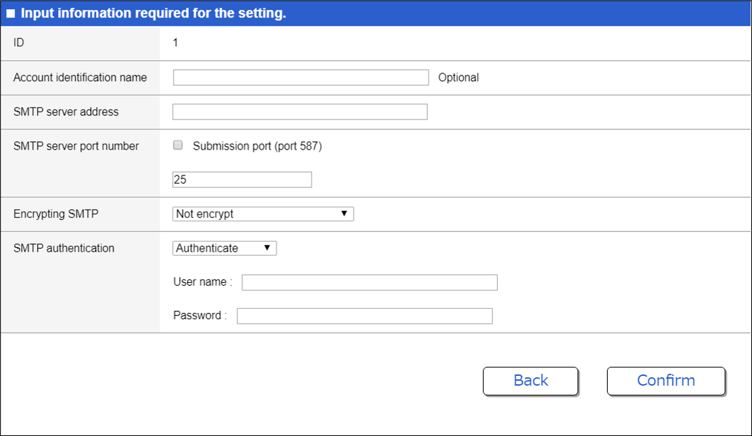
3.3 Email Template Settings
Email template settings can be specified by clicking [Advanced settings] - [Email notification] in the Web GUI to display the List of email notification settings.
Press the [New] button or the [Setting] button for an existing setting to display email notification settings.
In email notification settings, specify the following settings.
- Source (From)
- Recipient (To)
- Subject
If the Use default subject box is checked, then the email subject will always be in the form Notification from (device name).
- Content of notification
Error types can be specified in detail for Detect LAN map errors, so that only the specified type of notifications are output.
- Email sending wait time
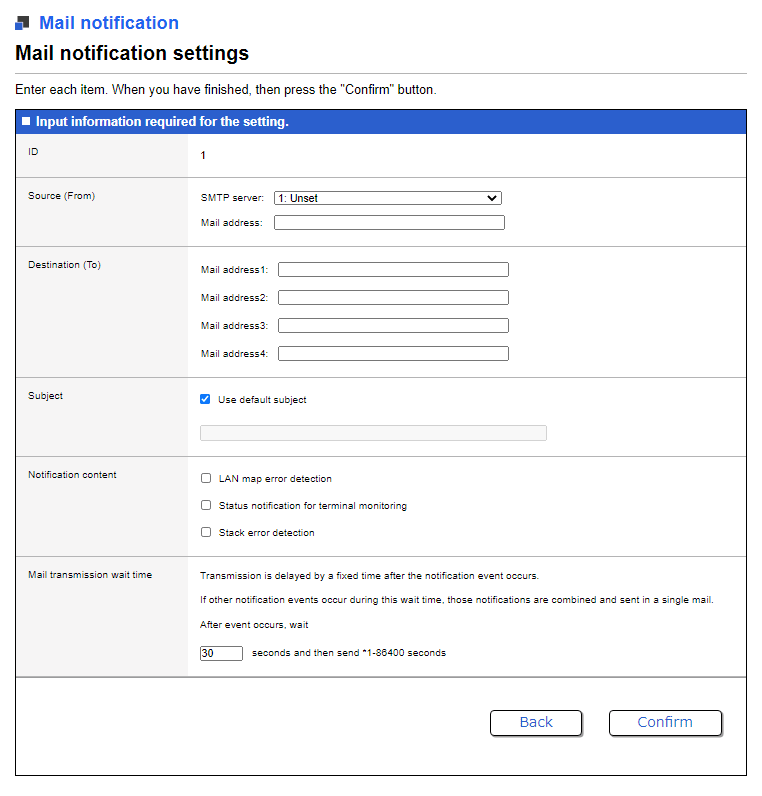
3.4 Functions that Support Email Notification
The following functions support email notification.
LAN map
The following notification events can be included in email notifications.
| Category | Type | Event | Description |
|---|---|---|---|
| Main Unit Error | Fan error | Fan lock | Fan stopped |
| Fan speed | Fan rotation speed increased | ||
| Fan stop | A specific fan stopped | ||
| Power supply error | Power voltage | Power supply voltage exceeded the upper threshold value | |
| Power supply | Overcurrent occurred in power supply | ||
| Temperature error | CPU temperature CPU temperature error PHY temperature PHY temperature error SFP temperature SFP module temperature error Unit temperature Unit temperature error PSE temperature PSE temperature error MAC temperature MAC temperature error | Yamaha switch temperature (CPU, PHY, SFP module, main unit, PSE, or MAC temperature) exceeded the upper threshold value | |
| The Yamaha switch temperature returned to normal | |||
| Thermal sensor invalid | A Yamaha switch temperature sensor error occurred | ||
| Loop Detection | Loop was detected | Loop detect | Loop was detected at a port |
| The loop detected at the port was resolved | |||
| SFP Optical Input Level Error | SFP optical input level error | SFP RX power | SFP optical input level exceeded the threshold value |
| SFP optical input level returned to the normal range | |||
| Transmission Queue Monitoring | Sending queue usage ratio error | Queue usage rate | Sending queue usage ratio increased |
| Sending queue usage ratio reached upper limit | |||
| Sending queue usage ratio returned to normal value | |||
| PoE Power Supply | Temperature error | Over temperature | Power supply stopped due to a temperature error |
| Maximum power supply capacity was exceeded | Over supply | The power supply exceeded the maximum supply capacity | |
| Power supply error | Power failure | The power supply source malfunctioned | |
| Power supply stopped due to a power supply class error | Class failure | Power supply was stopped because a class greater than the power supply class setting was detected at the power supply port | |
| Power supply stopped due to a class 4 power supply | Forced terminate | Power supply to a port that was being supplied class 3 (15.4 W) power was stopped due to a class 4 (30 W) power supply at the port | |
| Power supply stopped due to overcurrent | Over current | Power supply stopped because an excessive current was supplied to a port | |
| Power supply stopped because power supply capacity was exceeded | PoE state error(over-supply) | The power supply exceeded the maximum supply capacity | |
| Maximum power supply capacity exceeded has been resolved | |||
| Power supply stopped due to temperature error | PoE state error (over-temperature) | Power supply stopped due to a temperature error | |
| Power supply stop due to temperature error was resolved | |||
| Power supply stopped due to stoppage of fan | PoE state error (fanlock) | Power supply stopped because the fan stopped | |
| Power supply stop due to stopped fan was resolved | |||
| Power supply stopped due to power supply error | PoE state error(power-failure) | Power supply stopped due to a PoE power supply error | |
| Snapshot | Invalid device connected | Illegal equipment (SnapShot) | Device not registered in snapshot was detected |
| Invalid device connection was resolved | |||
| Connection port mismatch | Port mismatch (SnapShot) | Device with a connection port that differs from snapshot was detected | |
| Connection port mismatch was resolved | |||
| Device lost | Disappearance equipment (SnapShot) | A device registered in the snapshot is not connected | |
| Device loss was resolved | |||
| L2MS Manager Duplication | L2MS manager duplication | L2MS manager duplication | A duplicate L2MS manager was detected |
| The L2MS manager duplication was resolved |
Terminal monitoring function
The following notification events can be included in email notifications.
| Category | Type | Description |
|---|---|---|
| Ping monitoring | Up detection | Terminal up was detected |
| Down detection | Terminal down was detected | |
| Frame input volume monitoring | Up detection | Terminal up was detected |
| Down detection | Terminal down was detected | |
| LLDP monitoring | Up detection | Terminal up was detected |
| Down detection | Terminal down was detected |
Stack function
The following notification events can be included in email notifications.
| Type | Description |
|---|---|
| Stack port link down | The stack port connected to the member switch went link-down |
| Heartbeat error detection | A member switch heartbeat error was detected |
| Member switch was upgraded | A member switch was upgraded to a main switch |
3.5 Email Body Example
The body of a notification email includes content such as the following.
For details, refer to the technical reference for each function.
Up to 100 items can be included in one notification email.
Model: SWX3220-16MT                  *Model name
Revision: Rev.4.02.00                *Firmware version
Name: SWX3220-16MT_XXXXXXXX          *Host name
Time: 2017/06/13 11:42:56            *Email sending time
Template ID: 1                       *Email template ID

<<<<<<<<<<<<<<<<<<<<<<<<    Lan Map Information    >>>>>>>>>>>>>>>>>>>>>>>>>

[SFP RX Power]

  Type                                Device_Name
  MAC_Address                         Err_Port
  Route
  State
============================================================================
(Detected: 2017/06/13 10:09:40  Recovered: 2017/06/13 10:10:10)
  SWX2310P-10G                        SWX2310P-10G_S4K000398
  00a0.deae.b89c                      1.9
  port1.7(UpLink:1.5)
  Low
----------------------------------------------------------------------------

[Queue Usage Rate]

  Type                                Device_Name
  MAC_Address                         Err_Port
  Route
  State
============================================================================
(Detected: 2017/06/13 10:15:42  Recovered: 2017/06/13 10:17:24)
  SWX2310P-10G                        SWX2310P-10G_S4K000398
  00a0.deae.b89c                      1.6
  port1.7(UpLink:1.5)
  Full(Queue:2)
----------------------------------------------------------------------------

[Fan Lock]

  Type                                Device_Name
  MAC_Address
  Route
============================================================================
(Detected: 2017/06/13 10:28:43  Recovered: ----/--/-- --:--:--)
  SWX2200-8PoE                        SWX2200-8PoE_S45000345
  00a0.de83.4146
  port1.5(UpLink:2)
----------------------------------------------------------------------------
(Detected: 2017/06/13 10:42:13  Recovered: 2017/06/13 10:42:22)
  SWX2200-24G                         SWX2200-24G_X00000344
  00a0.de2a.dbbb
  port1.1(UpLink:23)
----------------------------------------------------------------------------

<<<<<<<<<<<<<<<<<<    Terminal Monitoring Information    >>>>>>>>>>>>>>>>>>>

[via Ping]

 Date                      Status    IP Address        Description
----------------------------------------------------------------------------
 2017/06/13 Thu 10:42:56   UP        192.168.100.155   IP_Camera_1
 2017/06/13 Thu 10:51:00   DOWN      192.168.100.155   IP_Camera_1
 2017/06/13 Thu 10:54:02   UP        192.168.100.10    Wireless_AP_1
 2017/06/13 Thu 11:29:27   UP        192.168.100.155   IP_Camera_1
 2017/06/13 Thu 11:30:31   DOWN      192.168.100.10    Wireless_AP_1

[via Bandwidth Usage]

 Date                      Status    Interface         Description
----------------------------------------------------------------------------
 2017/06/13 Thu 10:45:43   UP        port1.4           IP_Camera_2
 2017/06/13 Thu 10:45:56   UP        port1.6           Note_PC_1
 2017/06/13 Thu 10:50:00   DOWN      port1.6           Note_PC_1
 2017/06/13 Thu 10:53:27   DOWN      port1.4           IP_Camera_2

[via LLDP]

 Date                      Status    Interface         Description
----------------------------------------------------------------------------
 2017/06/13 Thu 10:53:56   UP        port1.3           Note_PC_2
 2017/06/13 Thu 11:11:54   DOWN      port1.3           Note_PC_2
 2017/06/13 Thu 11:14:24   UP        port1.3           Note_PC_2

<<<<<<<<<<<<<<<<<<<<<<<<<<    Stack Information    >>>>>>>>>>>>>>>>>>>>>>>>>

 Date                      Information
----------------------------------------------------------------------------
 2017/06/13 Thu 10:53:44   The stack port changed state to down. (port1.27)
 2017/06/13 Thu 10:53:46   Promoted to a main. (Old main ID : 1)
 2017/06/13 Thu 10:59:10   Occurred the heartbeat error. (ID : 1)
3.5.1 Content of LAN map notifications
Content of notifications for each event
The content of LAN map notification emails differs depending on the event type.
The content of notifications for each event type is indicated below.
| Event | Type Device_Name MAC_Address | Comment | Stack_ID | Err_Port | Fan_number | Route | Route(SnapShot) | State |
|---|---|---|---|---|---|---|---|---|
| Fan lock | ✓ | - | - | - | - | ✓ | - | - |
| Fan speed | - | ✓ | - | - | ✓ | - | - | |
| Fan stop | - | ✓ | - | ✓ | ✓ | - | - | |
| Power voltage Power supply | - | ✓ | - | - | ✓ | - | - | |
| CPU temperature CPU temperature error PHY temperature PHY temperature error SFP temperature SFP module temperature error Unit temperature Unit temperature error PSE temperature PSE temperature error MAC temperature MAC temperature error Thermal sensor invalid | - | ✓ | - | - | ✓ | - | - | |
| Loop detect | - | - | ✓ | - | ✓ | - | - | |
| SFP RX power | - | - | ✓ | - | ✓ | - | ✓ | |
| Queue usage rate | - | - | ✓ | - | ✓ | - | ✓ | |
| Over temperature Over supply Power failure | - | - | - | - | ✓ | - | - | |
| Class failure Forced terminate Over current | - | - | ✓ | - | ✓ | - | - | |
| PoE state error(over-supply) PoE state error (over-temperature) PoE state error (fanlock) PoE state error(power-failure) | - | ✓ | - | - | ✓ | - | - | |
| Illegal equipment (SnapShot) | ✓ | - | - | - | ✓ | - | - | |
| Port mismatch (SnapShot) | ✓ | - | - | - | ✓ | ✓ | - | |
| Disappearance equipment (SnapShot) | ✓ | - | - | - | - | ✓ | - | |
| L2MS manager duplication | ✓ | - | ✓ | - | ✓ | - | - |
Detailed content of notification
A detailed description of the various information included notifications is indicated below.
| Content of notification | Example of content | Description |
|---|---|---|
| Detected | Detected: 2021/10/01 8:25:40 | Indicates the date/time the error occurred. |
| Recovered | Recovered: 2021/10/01 10:09:40 | Indicates the date/time the error was resolved. |
| Type | SWX3220-16MT | Indicates the model name. |
| Device_Name | SWX3220-16MT_XXXXXXXXXX | Indicates the device name. |
| MAC_Address | ac44.f2xx.xxxx | Indicates the MAC address. |
| Comment | Snapshot: Comment | Indicates comments specified in the LAN map device list. |
| L2MS manager duplication: ac44.f2xx.xxxx | Indicates the MAC address of duplicate L2MS managers. | |
| Stack_ID | 1 | Indicates the stack ID. |
| Err_Port | 1.5 | Indicates the port number where the error occurred. |
| Fan_number | 1 | Indicates the fan number where the error occurred. |
| Route | port 1.20 (UpLink: 1.2) | Indicates routing information for applicable devices. |
| Route(SnapShot) | port 1.20 (UpLink: 1.2) | Indicates routing information on the snapshot for applicable devices. |
| State | SFP optical input level error: Low | Indicates SFP optical input level as either “Low” or “High”. |
| Transmission queue monitoring: Full (Queue: 2) | Indicates either “Busy” or “Full” as the transmission queue usage status and the transmission queue number. |
4 Related Commands
Related commands are indicated below.
For details on the commands, refer to the Command Reference.
List of related commands
| Operations | Operating Command |
|---|---|
| SMTP mail server setting | mail server smtp host |
| SMTP mail server name setting | mail server smtp name |
| Email notification trigger settings | mail notify trigger |
| Email sending template setting mode | mail template |
| Email sending server ID setting | send server |
| Email sender address setting | send from |
| Email recipient address setting | send to |
| Email subject setting | send subject |
| Email wait time setting | send notify wait-time |
| Email certificate setting | mail send certificate |
| Email certificate notification setting | mail send certificate-notify |
| Certificate expiration date notification timing setting | mail certificate expire-notify |
| Show email information | show mail information |
5 Points of Caution
The following are precautions related to SMTP authentication.
- The SMTP authentication only supports the LOGIN method.
- PLAIN, CRAM-MD5, and other methods are not supported.
Precautions for using firmware not compatible with the email notification function.
- If the firmware is updated from a version that does not support a command to a version that does support the command, commands specified in the Web GUI are directly carried over as command settings.
- To revert to the firmware version that does not support the commands, any changes to settings made using the firmware that does support the commands are not migrated and must be specified again after restoring the older version.
- If no settings were changes, then the current settings can be maintained.
The following are precautions related to LAN map error detection.
- Errors are indicated in notifications as active until the error is resolved, even if the error notification is disabled without resolving the error.
- Specifically, even after a notification is disabled, an email is sent after the error is resolved and is included in emails about the occurrence of other errors.
6 Related Documentation
LLDP
1 Function Overview
LLDP is a protocol for passing device management information between a device and its neighboring devices.
This is a simple protocol in which a device unidirectionally advertises its own information and neighbor devices receive this information. However, since LLDP-compliant devices maintain the information received from neighbor devices as MIB objects, the user can access this information via SNMP and ascertain what type of devices are connected to which interfaces are.
2 Definition of Terms Used
- LLDP
- Link Layer Discovery Protocol.
This is defined in IEEE 802.1AB.
- LLDP-MED
- LLDP for Media Endpoint Devices.
This is defined in ANSI/TIA-1057.
3 Function Details
3.1 Operating Specifications
3.1.1 Basic Specifications
This product supports the following operations.
- LLDP frames are transmitted from any LAN/SFP port to convey information about the device itself.
- LLDP frames are received at any LAN/SFP port to obtain information about neighboring devices.
- Information transmitted via LLDP about the device itself, and information obtained via LLDP about neighbor devices, etc., can be referenced via SNMP.
LLDP sends and receives information using Type, Length, and Value (TLV) attributes.
For details on the TLV information sent by this product, refer to 3.2 TLV list.
This product’s LLDP supports the following MIBs of SNMP. For details, refer to 3.3 Supported MIBs.
- LLDP-MIB
- LLDP-V2-MIB
- LLDP-EXT-MED-MIB
The following settings are required in order to use the LLDP function.
- Use the lldp run command to enable the system-wide LLDP function.
- Use the lldp-agent command to create an LLDP agent for the applicable interface.
- Use the set lldp command to specify the LLDP frame transmit/receive mode.
With the default settings of this product, the LLDP function is disabled.
LLDP frames are always transmitted without tags, regardless of the VLAN settings of the transmitting switch port.
They are also transmitted without tags from a trunk port without a native VLAN.
3.1.2 Transmitted information settings
Use the following commands to specify the LLDP frames that are transmitted from the device itself. There are also some TLVs (required TLVs) that are transmitted regardless of the settings of the following commands.
- tlv-select basic-mgmt command (basic management TLV)
- tlv-select ieee-8021-org-specific command (IEEE 802.1 TLV)
- tlv-select ieee-8023-org-specific command (IEEE 802.3 TLV)
- tlv-select med command (LLDP-MED TLV)
The system name and description that are transmitted in the basic management TLVs are specified by the lldp system-name command and the lldp system-description command.
The type of management address is set by the set management-address-tlv command.
3.1.3 Transmission timer setting
The interval at which LLDP frames are sent is specified by the set timer msg-tx-interval command.
The multiplier for calculating the hold time (TTL) for device information is set by the set msg-tx-hold command.
The TTL for LLDP transmission is the result of the following calculation. The default is 121 seconds.
- TTL = ( value set by the “set timer msg-tx-interval” command ) × ( value set by the “set msg-tx-hold” command ) + 1 (second)
When a neighbor device is connected to a LAN/SFP port for which LLDP frame transmission is enabled, LLDP frames are transmitted rapidly at a fixed interval according to the high-speed transmission interval setting.
The transmission interval and the number of transmissions for high speed transmission are set by the set timer msg-fast-tx command and the set tx-fast-init.
If from a state in which LLDP frame transmission is enabled, the set lldp command is used to disable it, this product transmits a shut-down frame, notifying the neighbor device that LLDP frame transmission has stopped.
Subsequently, even if LLDP frame transmission is once again enabled, LLDP frame transmission to the neighbor device is stopped for a time.
The stopped duration until the next transmission occurs after transmitting the shutdown frame is set by the set timer reinit-delay command.
3.1.4 Maximum connected devices setting
The maximum number of connected devices that can be managed by the corresponding port is set by the set too-many-neighbors limit command.
The default value for the maximum number of connected devices is 5 devices.
3.1.5 Checking LLDP information
LLDP interface settings and received information about neighbor devices can be checked by using the show lldp interface command or the show lldp neighbors command.
To clear the LLDP frame counter, use the clear lldp counters command.
3.1.6 Other functions using LLDP
This product provides a function that uses LLDP to automatically make optimal settings for the Dante digital audio network. The Dante optimization settings function is set by the lldp auto-setting command. For details, refer to Dante optimization setting function.
This product also provides a function that uses LLDP to monitor the live/dead state of a specific connected terminal. For details, refer to Terminal monitoring.
For the voice VLAN function, you can use LLDP-MED to make voice traffic settings for IP telephony. For details, refer to VLAN.
3.2 TLV list
The TLVs supported by this product are listed below.
- Required TLVs
- Basic management TLVs
- IEEE 802.1 TLV
- IEEE 802.3 TLV
- LLDP-MED TLV
For the detailed specification of each TLV, refer to IEEE 802.1AB (LLDP) and ANSI/TIA-1057 (LLDP-MED).
The TLVs that are transmitted by this product are explained below.
3.2.1 Required TLVs
If LLDP frame transmission is enabled, these TLVs are always transmitted.
Three TLVs are transmitted: chassis ID, port ID, and TTL.
The required TLVs are shown below.
Required TLVs
| Type | Description | Length | Value (only fixed values are listed) |
|---|---|---|---|
| Chassis ID | Chassis ID | 6 bytes | MAC address of the device |
| Port ID | Port ID | 7–8 bytes | Port name (portX.X) |
| Time To Live (TTL) | Time to keep device information (seconds) | 2 bytes |
3.2.2 Basic management TLVs
These TLVs are transmitted if LLDP frame transmission is enabled and the tlv-select basic-mgmt command is specified.
System-related management information is transmitted, such as name, system capabilities, and address.
The basic management TLVs are as follows.
Basic management TLVs
| Type | Description | Length | Value (only fixed values are listed) |
|---|---|---|---|
| Port Description | Port description text string | 0–255 bytes | |
| System Name | System name text string Default: Host name | 0–255 bytes | |
| System Description | System description text string Default: device name + firmware revision | 0–255 bytes | |
| System Capabilities | The functions supported by the system | 2 bytes | 0x0004 (bridge) |
| The system’s functions that are in an enabled state | 2 bytes | 0x0004 (bridge) | |
| Management Address | The management address IP address (4 bytes) or MAC address (6 bytes) | 4 or 6 bytes | |
| Interface sub-type | 1 byte | 0x02 (ifIndex) | |
| Interface number | 4 bytes | ifIndex value |
3.2.3 IEEE 802.1 TLV
These TLVs are transmitted if LLDP frame transmission is enabled and the tlv-select ieee-8021-org-specific command is specified.
These transmit information such as VLAN and link aggregation for the corresponding port.
The IEEE 802.1 TLVs are shown below.
IEEE 802.1 TLV
| Type | Description | Length | Value (only fixed values are listed) |
|---|---|---|---|
| Port VLAN ID | Port VLAN number | 2 bytes | |
| Port and Protocol VLAN ID | Support for protocol VLAN, and whether enabled or disabled | 1 byte | 0x00 (no support) |
| Protocol VLAN number | 2 bytes | 0x0000 | |
| Protocol Identity | bytes string that identifies the protocol | 0–255 bytes | |
| Link Aggregation | Link aggregation capability and status | 1 byte | |
| ifIndex number of aggregation logical interface | 4 bytes | ||
| VLAN Name | Name of VLAN to which the port is associated | 0–32 bytes |
3.2.4 IEEE 802.3 TLV
These TLVs are transmitted if LLDP frame transmission is enabled and the tlv-select ieee-8023-org-specific command is specified.
Auto negotiation support information etc. for the corresponding port is transmitted.
The IEEE 802.3 TLVs are shown below.
IEEE 802.3 TLV
| Type | Description | Length | Value (only fixed values are listed) |
|---|---|---|---|
| MAC/PHY Configuration/Status | Auto negotiation support, and whether enabled or disabled | 1 byte | |
| Communication methods for which auto negotiation is possible | 2 bytes |
| |
| Operational MAU Type Communication speed and duplex mode (IETF RFC 4836) | 2 bytes | ||
| Link Aggregation | Link aggregation capability and status | 1 byte | |
| ifIndex number of aggregation logical interface | 4 bytes | ||
| Maximum Frame Size | Maximum frame size | 2 bytes |
3.2.5 LLDP-MED TLV
These TLVs are transmitted if LLDP frame transmission is enabled and the tlv-select med command is specified.
These are used to transmit network policy information, for example.
The LLDP-MED TLVs are shown below.
LLDP-MED TLV
| Type | Description | Length | Value (only fixed values are listed) |
|---|---|---|---|
| LLDP-MED Capabilities | LLDP-MED TLVs that can be transmitted | 2 bytes | 0x0003 (LLDP-MED Capabilities, Network Policy)
|
| Device type | 1 byte | 0x04 (Network Connectivity) | |
| Network Policy | Application type | 1 byte | 0x01 (Voice) |
| Voice VLAN information | 3 bytes |
Network policy is only transmitted via the port specified by Voice VLAN.
3.3 Supported MIBs
Refer to the following SNMP MIB Reference for information on the MIBs that are supported.
4 Related Commands
Related commands are shown below.
For details on the commands, refer to the Command Reference.
List of related commands
| Operations | Operating Commands |
|---|---|
| Enable LLDP function | lldp run |
| Set system description text string | lldp system-description |
| Set system name | lldp system-name |
| Create LLDP agent | lldp-agent |
| Set LLDP transmission/reception mode | set lldp |
| Set management address type | set management-address-tlv |
| Set basic management TLV | tlv-select basic-mgmt |
| Set IEEE-802.1 TLV | tlv-select ieee-8021-org-specific |
| Set IEEE-802.3 TLV | tlv-select ieee-8023-org-specific |
| Set LLDP-MED TLV | tlv-select med |
| Set LLDP frame transmission interval | set timer msg-tx-interval |
| Set duration to stop transmission following LLDP transmission stop until transmission is once again possible | set timer reinit-delay |
| Set multiplier for calculating the time to maintain device information (TTL) | set msg-tx-hold |
| Set LLDP frame transmission interval for high-speed transmission term | set timer msg-fast-tx |
| Set number of LLDP frames transmitted for high-speed transmission term | set tx-fast-init |
| Set maximum number of devices that can be managed by an individual port | set too-many-neighbors limit |
| Show interface status | show lldp interface |
| Show connected device information for all interfaces | show lldp neighbors |
| Clear LLDP frame counters | clear lldp counters |
| Set Dante optimization function using LLDP | lldp auto-setting |
5 Examples of Command Execution
5.1 Set LLDP frame transmission/reception
For port1.1, enable LLDP frame transmission/reception.
Basic management TLVs, IEEE 802.1 TLVs, IEEE 802.3 TLVs, and LLDP-MED TLVs are transmitted.
Set the LLDP frame transmission interval to 60 seconds. Set the LLDP frame TTL to 181 seconds.
Set “SWITCH1” as the name of the transmitting system.
Specify 10 as the maximum number of connected devices managed by the port.
Yamaha#configure terminal
Yamaha(confif)#lldp system-name SWITCH1 ... (Set system name)
Yamaha(config)#interface port1.1
Yamaha(config-if)#lldp-agent ... (Create LLDP agent and transition modes)
Yamaha(lldp-agent)#tlv-select basic-mgmt ... (Set basic management TLV)
Yamaha(lldp-agent)#tlv-select ieee-8021-org-specific ... (Set IEEE 802.1 TLV)
Yamaha(lldp-agent)#tlv-select ieee-8023-org-specific ... (Set IEEE 802.3 TLV)
Yamaha(lldp-agent)#tlv-select med ... (Set LLDP-MED TLV)
Yamaha(lldp-agent)#set timer msg-tx-interval 60 ... (Set transmission interval)
Yamaha(lldp-agent)#set msg-tx-hold 3 ... (Set multiplier for TTL calculation: TTL = 60 × 3 + 1 = 181 seconds)
Yamaha(lldp-agent)#set too-many-neighbors limit 10 ... (Set maximum number of connected devices)
Yamaha(lldp-agent)#set lldp enable txrx ... (Set LLDP transmission/reception mode)
Yamaha(lldp-agent)#exit
Yamaha(config-if)#exit
Yamaha(config)#lldp run ... (Enable LLDP function)
Yamaha(config)#exit
5.2 Show LLDP interface status
Show the port1.1 LLDP interface status.
Yamaha#show lldp interface port1.1  ... (Show interface information)
Agent Mode                    : Nearest bridge
Enable (tx/rx)                : Y/Y
Message fast transmit time    : 1
Message transmission interval : 30
Reinitialization delay        : 2
MED Enabled                   : Y
Device Type                   : NETWORK_CONNECTIVITY
LLDP Agent traffic statistics
  Total frames transmitted       : 0
5.3 Show LLDP connected device information
Show LLDP connected device information.
Yamaha#show lldp neighbors  ... (Show connected device information)
Interface Name           : port1.1
System Name              : SWX3100-10G
System Description       : SWX3100 Rev.4.01.02 (Mon Dec  4 12:33:18 2019)
Port Description         : port1.3
System Capabilities      : L2 Switching
Interface Numbering      : 2
Interface Number         : 5003
OID Number               :
Management MAC Address   : ac44.f230.0000
Mandatory TLVs
  CHASSIS ID TYPE
    IP ADDRESS           : 0.0.0.0
  PORT ID TYPE
    INTERFACE NAME       : port1.3
  TTL (Time To Live)     : 41
8021 ORIGIN SPECIFIC TLVs
  Port Vlan id                : 1
  PP Vlan id                  : 0
  Remote VLANs Configured
    VLAN ID                   : 1
    VLAN Name                 : default
  Remote Protocols Advertised :
    Multiple Spanning Tree Protocol
  Remote VID Usage Digestt    : 0
  Remote Management Vlan      : 0
  Link Aggregation Status     :
  Link Aggregation Port ID    :
8023 ORIGIN SPECIFIC TLVs
  AutoNego Support            : Supported Enabled
  AutoNego Capability         : 27649
  Operational MAU Type        : 30
  Power via MDI Capability (raw data)
    MDI power support         : 0x0
    PSE power pair            : 0x0
    Power class               : 0x0
    Type/source/priority      : 0x0
    PD requested power value  : 0x0
    PSE allocated power value : 0x0
  Link Aggregation Status     :
  Link Aggregation Port ID    :
  Max Frame Size              : 1522
LLDP-MED TLVs
  MED Capabilities            :
    Capabilities
    Network Policy
  MED Capabilities Dev Type   : End Point Class-3
  MED Application Type        : Reserved
  MED Vlan id                 : 0
  MED Tag/Untag               : Untagged
  MED L2 Priority             : 0
  MED DSCP Val                : 0
  MED Location Data Format    : ECS ELIN
    Latitude Res      : 0
    Latitude          : 0
    Longitude Res     : 0
    Longitude         : 0
    AT                : 0
    Altitude Res      : 0
    Altitude          : 0
    Datum             : 0
    LCI length        : 0
    What              : 0
    Country Code      : 0
    CA type           : 0
  MED Inventory
6 Points of Caution
None
7 Related Documentation
- SWX3220 Series Technical Data (Basic Functions)
- Maintenance and operation functions
- LLDP automatic setting
LLDP automatic setting
1 Function Overview
The LLDP automatic setting function automatically sets settings based on information in LLDP notifications in proprietary LLDP frames sent and received between Yamaha switches and Yamaha wireless AP.
The following functionality can be achieved by LLDP automatic settings.
- RADIUS server automatic settings
- This automatic specifies information about RADIUS servers currently operating at the Yamaha wireless AP in the Yamaha switch. That makes it easy to configure an authentication function in Yamaha wireless APs as a RADIUS server or in Yamaha switches as a RADIUS client.
- Yamaha wireless AP dead/alive monitoring
- This uses LLDP to automatically monitor whether Yamaha wireless APs connected to the product are dead or alive.
To determine Yamaha switch and wireless AP models that support LLDP automatic setting function, refer to the following.
2 Definition of Terms Used
LLDP
Link Layer Discovery Protocol。
This is defined in IEEE 802.1AB.
3 Function Details
3.1 Key specifications
If LLDP automatic setting function is enabled, proprietary LLDP frames will be sent and received between Yamaha switches and Yamaha wireless AP.
LLDP automatic settings are specified using the lldp auto-setting command.
LLDP automatic setting function is enabled in default settings.
In order to use this function, reception of LLDP frames must be enabled.
For this reason, check in advance that the following settings have been made.
- Enable LLDP functionality for the overall system using the lldp run command.
- Create LLDP agents at applicable interfaces using the lldp-agent command.
- Specify the LLDP frame transmit/receive mode using the set lldp command.
LLDP frame transmission and reception are enabled in product default settings.
3.2 RADIUS server automatic settings
This function automatically specifies information in the product about RADIUS servers currently operating at Yamaha wireless APs (clusters). That makes it easy to configure an authentication function in Yamaha wireless APs as a RADIUS server or in Yamaha switches as a RADIUS client.
Authentication settings for each port on the product must be set manually by the user based on the given environment. For more details about authentication settings, refer to Port authentication functions in the technical reference.
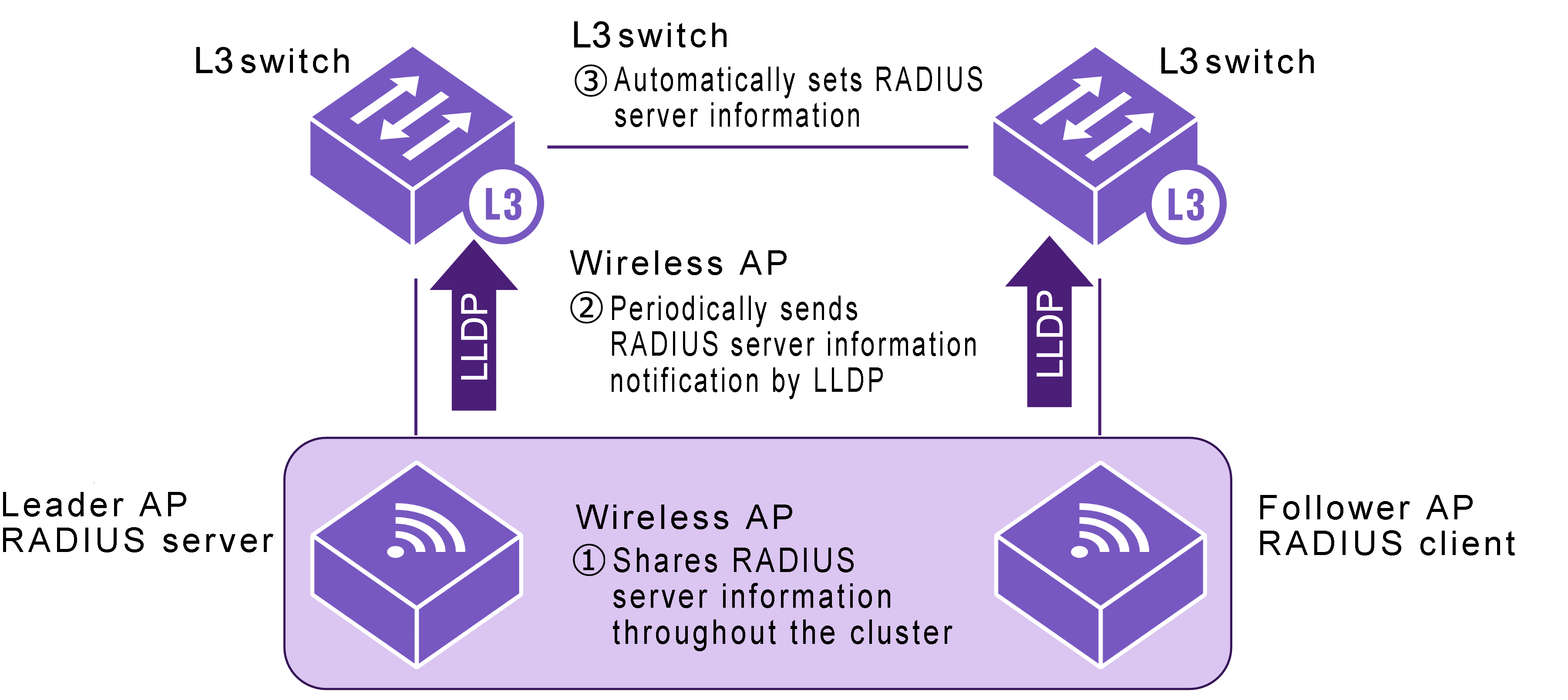
3.2.1 RADIUS server information sent by Yamaha wireless APs
Yamaha wireless APs send RADIUS server information based on the following criteria.
- LLDP and LLDP automatic settings are enabled
- Cluster functionality is enabled
- Cluster leader APs are functioning as a RADIUS server
- Cluster follower APs are functioning as RADIUS client that connects to a leader AP RADIUS server.
For details about Yamaha wireless AP settings, refer to the Yamaha wireless AP technical reference.
If the criteria for sending information are satisfied, Yamaha wireless APs send notifications with the following RADIUS server information at regular intervals.
- IP address of the RADIUS server
- UDP port number for RADIUS server authentication
- Shared password for communicating with RADIUS server
3.2.2 RADIUS server entry control
If the product LLDP automatic setting function is enabled and RADIUS server information is received from a Yamaha wireless AP, then a radius-server host command with an optional dynamic string added to the end is automatically specified in the running-config.
In the remaining explanation below, the radius-server host command appended by an optional dynamic string is referred to as a “dynamic entry”, whereas the manually specified radius-server host command is referred to as a “static entry”.
Dynamic entries appended with the optional dynamic string are not saved in the startup-config file, even if the write command is executed.
After dynamic entry is set by automatic settings, static entry can be set by manually deleting the dynamic option.
However, static entry cannot be changed to dynamic entry by manually adding the dynamic option.
- Example of Dynamic Entry of radius-server host Command
radius-server host 192.168.100.241 auth-port 1234 key EXAMPLE dynamic
Dynamic entries specified by LLDP automatic settings are appended with LLDP reception port number and validity period information.
If identical RADIUS server information is received from multiple ports, the RADIUS server information received from the port with the smallest port number is retained.
The TTL (Time to Live) value included in the received LLDP frame is specified as the validity period.
The default TTL value for LLDP frames sent from Yamaha wireless APs is 120 seconds.
If new RADIUS server information is received within TTL seconds, then the validity period is updated, whereas if new RADIUS server information is not received within TTL seconds, then the dynamic entry is deleted.
However, if an LLDP shutdown frame with TTL = 0 is received, then the dynamic entry is immediately deleted.
The show radius-server command can be used to confirm RADIUS server information, with the automatically specified RADIUS server host marked with an asterisk and
the LLDP reception port number (LLDP received port) and validity period (Expires) information also listed.
- Example of using the show radius-server command to show dynamic entry information
SWX#show radius-server
Server Host : 192.168.100.241*
 LLDP Received port : port1.2
 Expires : 00:00:33
 Authentication Port : 1234
 Secret Key : EXAMPLE
 Timeout : 10 sec
 Retransmit Count : 5
 Deadtime : 0 min

* - Assigned by LLDP.
A total of up to 8 RADIUS server information entries, including dynamic and static entries, can be specified for the product.
Using static entries is prioritized over using dynamic entries.
Therefore, even if the maximum number of RADIUS server information entries are already specified, new static entries can be specified if there are any dynamic entries among existing entries.
In that case, the dynamic entry with the highest LLDP reception port number is deleted.
3.2.3 Precautions
If the above functionality is used, note the following precautions.
- Connection to Yamaha wireless AP unit
- To enable automatic setting of RADIUS server information, Yamaha switches must be connected directly to Yamaha wireless AP that support LLDP automatic setting functionality.
- For Yamaha switches not directly connected to a Yamaha wireless AP, specify RADIUS server settings manually.
- Command input mode restrictions when the stack function is enabled
- If the stack function is enabled, users permitted to transition to the global configuration mode are restricted. For details, refer to Stack function.
- Because settings automatically transition to the global configuration mode if RADIUS server settings are received by LLDP from a Yamaha wireless AP and applied, users that are already in the global configuration mode via the console or who are in an individual configuration mode are forced to transition to the privileged EXEC mode.
- Characters permitted in shared passwords for communicating with RADIUS servers
- Question mark and space characters cannot be used. Do not use those characters when setting shared passwords (RADIUS server, client, or secret) for Yamaha wireless AP units.
- Set response wait time for the entire RADIUS server
- If multiple RADIUS servers are configured, set the auth timeout server-timeout command setting value, which sets the total wait time for all RADIUS servers, to a value equal to or larger than the product of the radius-server timeout command setting value times the radius-server retransmit command setting value plus one times the number of RADIUS servers. For command details, refer to the command reference.
3.3 Yamaha wireless AP dead/alive monitoring
When a Yamaha switch receives a request from a Yamaha wireless AP to start dead/alive monitoring, it automatically starts monitoring by LLDP whether the Yamaha wireless AP is dead or alive.
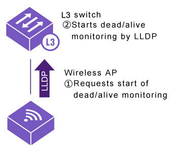
Yamaha wireless APs send dead/alive monitoring requests based on the following criteria.
- LLDP and LLDP automatic settings are enabled
If the dead/alive monitoring request is received with the LLDP automatic setting function enabled in the Yamaha switch, then an LLDP reception interval monitoring setting is registered for the LLDP reception port.
If no LLDP frame was received during a given period of dead/alive monitoring at the port where the setting was registered, then notification is sent that a communication interruption was detected at the SNMP trap and L2MS trap.
For details, refer to the technical reference for Terminal monitoring.
3.3.1 Precautions
If the above functionality is used, note the following precaution.
- If dead/alive monitoring is no longer necessary, such as after the Yamaha wireless AP connection port was changed, manually delete the settings that became unnecessary after the Yamaha wireless AP connection port was changed.
4 Related Commands
Related commands are indicated below.
For details, refer to the Command Reference.
List of related commands
| Operations | Operating commands |
|---|---|
| Enable LLDP automatic settings | lldp auto-setting |
| Enable LLDP function | lldp run |
| Create LLDP agent | lldp-agent |
| Set LLDP transmission/reception mode | set lldp |
| Set LLDP frame transmission interval | set timer msg-tx-interval |
| Set RADIUS server host | radius-server host |
| Set response wait time for a single RADIUS server | radius-server timeout |
| Set number of times to retransmit request to RADIUS server | radius-server retransmit |
| Show RADIUS server setting status | show radius-server |
| Set response wait time for the entire RADIUS server | auth timeout server-timeout |
5 Setting Examples
For instructions on how to configure respective Yamaha switch and wireless AP settings, function refer to the following.
6 Points of Caution
See the precautions indicated for each function.
7 Related Documentation
- SWX3220 Series Technical Data (Basic Functions)
- Maintenance and operation functions
- Terminal monitoring
Terminal monitoring
1 Function Overview
The terminal monitoring function checks the dead-or-alive state of specific terminals connected to the network switch.
The operating specifications for the terminal monitoring function are shown below.
Terminal monitoring function overview
Examples of an L2MS manager with an L3 switch and an L2MS agent with an intelligent L2 PoE switch are shown below.
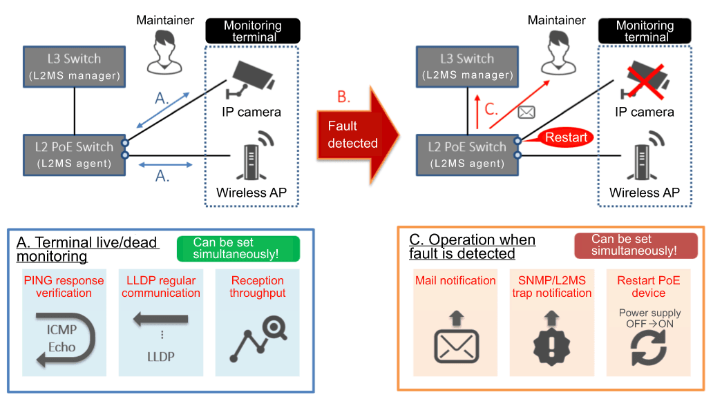
As dead/alive monitoring methods, the following three types are provided.
- Monitoring by ping
Ping (ICMP Echo request/reply) is issued at regular intervals to a terminal that has an IP address, and the terminal is determined to be down if there is no longer a response.
The user can specify the ping response wait time and the number of failures before the connection is determined to be down.
- Frame reception amount monitoring
The frame reception amount is monitored at regular intervals for an individual port, and the terminal is determined to be down if the traffic falls below a specified amount.
The user can specify the monitoring start threshold value and the threshold value at which a down condition is determined.
Monitoring starts when the traffic exceeds the monitoring start threshold value, and a down condition is determined when the traffic falls below the down decision threshold.
- LLDP reception interval monitoring
The LLDP received at regular intervals by an individual port is monitored.
Using the TTL which is a required item in the data portion of an LLDP packet, a down condition is determined if LLDP is not received within the TTL interval.
If monitoring detects a terminal fault (down), the following processing is automatically performed.
- Alert shown in dashboard screen
An indication that a fault (down) occurred for the monitored terminal is displayed in the alert screen of the dashboard.
- Alert shown in LAN map screen
If L2MS manager switch is used for terminal monitoring:
An indication that a fault (down) occurred for the monitored terminal is shown in the LAN map notification and history information.
If L2MS agent switch is used for terminal monitoring:
The L2MS trap function is used to notify the L2MS manager.
When the L2MS manager receives a notification, it uses the LAN map screen to indicate an error (down) occurred in a monitored terminal.
By the user’s choice, the following operations can be applied in parallel.
- Fault detection notification by mail
Notification that a monitored terminal has experienced a fault is sent to the desired recipient.
- Notification to the SNMP manager
A trap is sent to the SNMP manager specified by a command.
- Restart terminal by temporarily stopping the PoE power supply
If a down condition is detected on a port to which PoE power is being supplied, PoE power supply is temporarily turned off in an attempt to recover the monitored terminal.
2 Definition of Terms Used
None
3 Function Details
3.1 Monitoring by ping (ICMP Echo request/reply)
Specifications for terminal monitoring by ping are given below.
- The interval of ICMP Echo request transmission from the network switch is fixed at 5 seconds.
- The ICMP Echo request that is transmitted has the following format.
- As the ID field of the ICMP header, the unique ID assigned to each monitored terminal is specified.
- As the sequence field of the ICMP header, a number that is sequentially incremented from 0 is specified.
- The validity of the ICMP Echo reply is checked as follows.
- Whether the ID field of the ICMP header contains the ID that was specified when sending the request
- Whether the sequence field of the ICMP header contains the sequence number that was specified when sending the request
- The wait time for ICMP Echo reply can be changed in the range of 1–60 sec, and the default is 2 sec.
- The number of failures to receive the ICMP Echo reply from the monitored terminal after which a fault is determined can be set in the range of 1–100, and the default is twice.
- Monitoring via ping can be done for a maximum of 64 units.
- If sending an email notification or SNMP trap is enabled, they are sent in the following cases.
- When a terminal is detected to be down (sent every 24 hours while down)
- When a terminal is detected to be up (sent when monitoring is started or restored)
3.2 Monitoring by frame reception amount
The way in which this device monitors by frame reception amount is described below.
Overview of frame reception amount monitoring
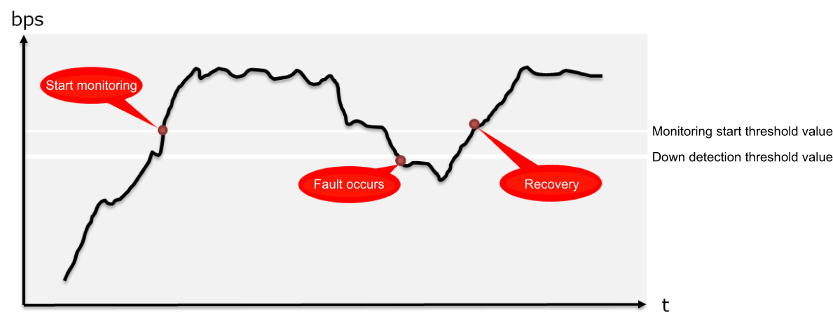
- At one-second intervals, the number of octets received at the port is referenced, and the number of octets received during one second is calculated.
- All ports are the object of observation.
- Using the number of octets received during one second and the link speed, the reception throughput (bps) and reception ratio (%) are calculated.
- Monitoring by frame reception amount starts when the monitoring start threshold value (bps) specified by the user is exceeded.
- After monitoring has started, a fault (down) is detected if the amount falls below the down detection threshold value (bps) specified by the user.
- If sending an email notification or SNMP trap is enabled, they are sent in the following cases.
- When a terminal is detected to be down
- When a terminal is detected to be up (sent when monitoring is started or restored)
3.3 Monitoring by LLDP
- Using the TTL which is a required item in the data portion of an LLDP frame, a down condition is determined if LLDP is not received within the TTL time.
- Monitoring starts when an LLDP frame is first received.
- This monitoring can be specified individually by port.
- If sending an email notification or SNMP trap is enabled, they are sent in the following cases.
- When a terminal is detected to be down
- When a terminal is detected to be up (sent when monitoring is started or restored)
- When a terminal stopped LLDP functionality
4 Related Commands
This function does not support settings via commands.
5. Settings via the Web GUI
Terminal monitoring settings can be done from [Advanced settings]-[Terminal monitoring] of the Web GUI.
Details on the settings in each screen can be referenced via the Web GUI help.
5.1 Terminal monitoring top page
The top page of terminal monitoring is shown below.
Terminal monitoring top page
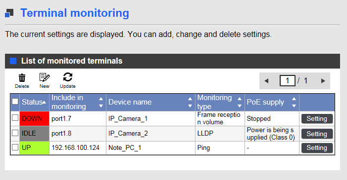
- If you want to newly add a terminal for monitoring, press the New icon.
- If you want to change a currently-specified monitored terminal, press the [Setting] button in the list.
If you want to delete a currently-specified monitored terminal, select the check box of that terminal, and press the [Delete] button.
- If you want to ascertain the current state of the monitored terminal for which you are making settings, press the [Update] button to acquire the latest state.
5.2 Adding or modifying a monitored terminal
The method for adding a new monitored terminal, or for making changes, is shown below for each method of monitoring.
- Monitoring by ping
- Monitoring frame input volumes
- Monitoring LLDP receiving intervals
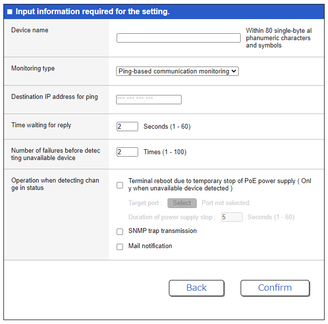
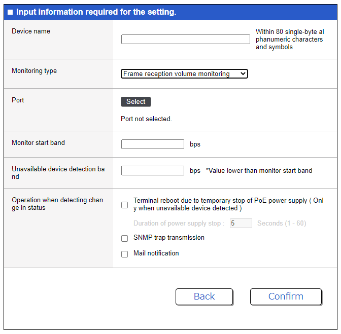
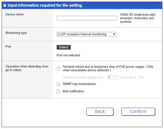
- Restart terminal by controlling PoE power supply can be specified only for models that support PoE power supply.
- Use the traffic observation function when deciding the monitoring start threshold value and the down detection threshold value settings for frame input volume monitoring.
- If you want mail notification to be sent in the event of a fault, you must separately make mail notification settings.
For details, refer to Technical reference: [Maintenance and operation functions] - [Mail notification] and to Web GUI help: [Advanced settings] - [Mail notification].
5.3. Checking the state of a monitored terminal
The state of a specified monitored terminal can be checked in the terminal monitoring gadget of the dashboard.
Dashboard terminal monitoring gadget
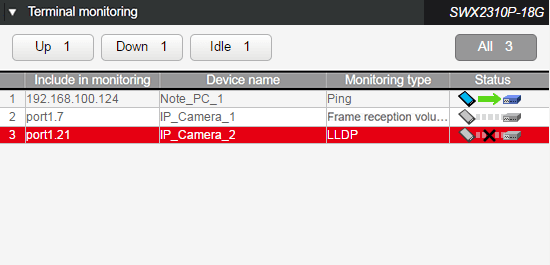
- For each monitored terminal, this shows the monitoring target, model name, monitoring type, and status.
- The following three states are shown as the state of the monitored terminal.
- Idle: Monitoring is not yet being performed:
- Up: The monitored terminal is operating correctly:
- Down: The monitored terminal is not operating correctly:
- Idle: Monitoring is not yet being performed:
- When you place the mouse cursor on the status field, the status of the monitored terminal is shown.
- If you click the [Idle] , [Up], or [Down] button in the upper part of the dashboard, only the monitored terminals that are in the corresponding state are shown. (The [All] button shows terminals of all states.)
- If not even one monitor terminal is registered, the display indicates “No monitored terminals are registered.”
6 Points of Caution
None
7 Related Documentation
- SWX3220 Series Technical Data (Basic Functions)
- Maintenance and operation functions
- Performance observation
Performance observation
1 Function Overview
This product provides a mechanism for constantly observing the system’s performance.
An overview of the function is given below.
Performance observation
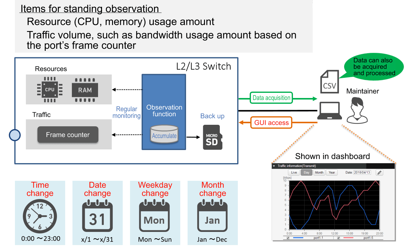
This product constantly observes the following two types of data.
- Resource usage: CPU and memory usage
- Traffic amount: The amount of communication port bandwidth used (transmission/reception)
Based on the results of observation, one year’s worth of the following change data is accumulated inside this product.
- Hourly change: Change for each hour (e.g. 0:00, 1:00, ...)
- Daily change: Change for each day of each month (e.g. 1/1, 1/2, ...)
- Weekly change: Change for each day of the week (e.g. SUN, MON, ...)
- Monthly change: Change for each month (e.g. Jan, Feb, ...)
The accumulated data can be backed up to an SD card. By accessing this product via the Web GUI, the maintainer can view the various types of change data including live data in the dashboard, and can also acquire the accumulated result in a PC.
Since the acquired data is in CSV format, it can also be manipulated using spreadsheet software on a PC.
By using this function, the maintainer can accomplish the following:
- Ascertain the short-term communication status
- Predict long-term future demand for network facilities
2 Definition of Terms Used
None
3 Function Details
3.1 Resource and traffic usage observation
Starting immediately after boot, this device automatically observes the CPU and memory and the transmit/receive throughput of each port every second.
The observed data is normalized using a moving average, and one year of data is saved in RAM.
3.3 Observation data backup
Backup of observation data can be specified only in the Web GUI.
Backup of observation data assumes that an SD card is inserted in this device.
If backup is enabled, the most recent hour of observation data every hour starting at the point it was enabled (e.g., 1:00, 2:00 ...) is saved on the SD card.
The saved data is dedicated binary data of this device.
The save-destination on the SD card and the file name of the backup data file are as follows.
Resource information
- Hourly change data
/[model name]/data/resource/YYYYMM_smsys_res_monitor_hour.bin
- Daily change data (data for each day)
/[model name]/data/resource/YYYYMM_smsys_res_monitor_day.bin
- Weekly change data
/[model name]/data/resource/YYYYMM_smsys_res_monitor_week.bin
- Monthly change data
/[model name]/data/resource/YYYY_smsys_res_monitor_month.bin
- Hourly change data
Traffic information
- Hourly change data
/[model name]/data/trf/YYYYMM_trf_bandwidth_hour.bin
- Daily change data
/[model name]/data/trf/YYYYMM_trf_bandwidth_day.bin
- Weekly change data
/[model name]/data/trf/YYYYMM_trf_bandwidth_week.bin
- Monthly change data
/[model name]/data/trf/YYYY_trf_bandwidth_month.bin
- Hourly change data
- [Model name] is the following.
- For the SWX2320-16MT: swx2320
- For the SWX2322P-16M: swx2322p
- For the SWX3220-16MT/16TMs : swx3220
- YYYY: year, MM: month are specified.
- Since this is a proprietary Yamaha format, it cannot be referenced.
3.4. Observation data export
Export of observation data to a PC can be executed only in the Web GUI.
As with backup data, export of observation data to a PC assumes that an SD card is inserted in this device.
The exported data is multiple CSV files compressed in zip format. The structure of the compressed files are given below.
- When resource observation data is exported
- zip file name: YYYYMMDDhhmmss_resource_csv.zip
- Folder structure
YYYYMMDDhhmmss_resource_csv +- 20170922_resource_hour.csv ... (CPU and memory data for each hour of 2017/9/22) +- : +- 20170925_resource_hour.csv ... (CPU and memory data for each hour of 2017/9/25) +- 201709_resource_day.csv ... (CPU and memory data for each day of 2017/9) - When transmission traffic observation data is exported
- zip file name: YYYYMMDDhhmmss_trf_tx_csv.zip
- Folder structure
YYYYMMDDhhmmss_trf_tx_csv +- 20170922_trf_tx_hour.csv ... (Transmission traffic data for each hour of 2017/9/22) +- : +- 20170925_trf_tx_hour.csv ... (Transmission traffic data for each hour of 2017/9/25) +- 201709_trf_tx_day.csv ... (Transmission traffic data for each day of 2017/9) - When reception traffic observation data is exported
- zip file name: YYYYMMDDhhmmss_trf_rx_csv.zip
- Folder structure
YYYYMMDDhhmmss_trf_rx_csv
    +- 20170922_trf_rx_hour.csv  ... (Reception traffic data for each hour of 2017/9/22)
    +-     :
    +- 20170925_trf_rx_hour.csv  ... (Reception traffic data for each hour of 2017/9/25)
    +- 201709_trf_rx_day.csv     ... (Reception traffic data for each day of 2017/9)
- YYYYMMDDhhmmss specifies the date and time at which export was executed (the date and time that the file was generated).
4 Related Commands
This function does not support settings via commands.
5. Settings via the Web GUI
Performance observation can be controlled from the following pages of the Web GUI.
- Viewing the resource usage amount
- This can be viewed in the [Dashboard] item [Resource information (graph)].
- Viewing the traffic usage amount
- This can be viewed in the [Dashboard] item [Traffic information (graph)].
- Backing up, clearing, or exporting observation data
- Select [Management], and then use [Maintenance] - [Summary data management] to make these settings.
Details on how to view and make settings in each screen can be referenced via the Web GUI help.
5.1 Viewing the resource usage amount
The resource information (graph) screen is shown below.
Example when Live is selected for resource information (graph)
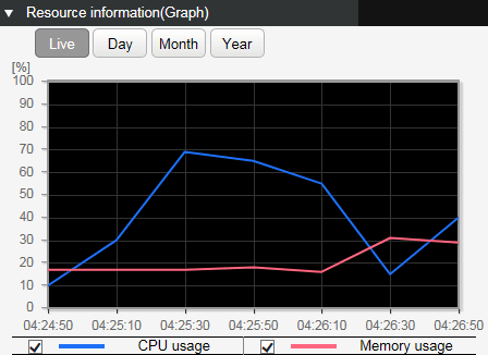
- The graph rendering can be changed using the following buttons.
Current status: [Live]
The various current usage ratios are obtained at one-second intervals and shown on the graph.
Hourly change: [Day]
The various usage ratios for the specified day are shown at one-hour intervals on the graph.
To specify the day, use the day-specifying box in the upper right of the gadget.
Daily change: [Month]
The various usage ratios for the specified month are shown at one-day intervals.
To specify the month, use the month-specifying box in the upper right of the gadget.
Monthly change: [Year]
The various usage ratios for the specified year are shown at one-month intervals.
To specify the year, use the select box in the upper right of the gadget.
- It is not currently possible to reference changes in the day of the week.
- If the CPU and memory usage ratios exceed 80%, then a warning message is shown on the dashboard.
If the ratio falls below 80% after having exceeded 80%, the warning is automatically cleared.
5.2 Viewing the traffic usage amount
The traffic usage amount (graph) screen is shown below.
Example of when traffic usage amount (graph) Day is selected / Example of transmission traffic
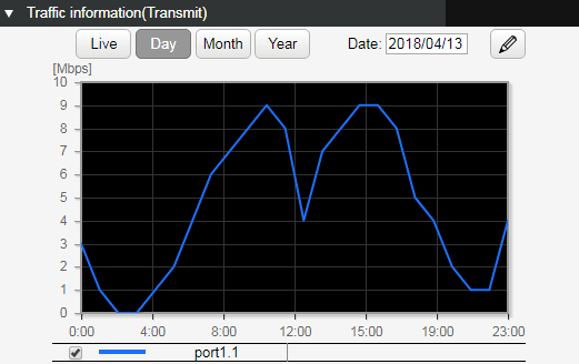
- The traffic usage amount of each port can be shown separately for transmission and reception.
- The graph rendering can be changed using the following buttons.
Current status: [Live]
The various current usage ratios are obtained at one-second intervals and shown on the graph.
The most recent two minutesof the obtained data is held and rendered on the graph.
Hourly change: [Day]
The various usage ratios for the specified day are shown at one-hour intervals on the graph.
To specify the day, use the day-specifying box in the upper right of the gadget.
Daily change: [Month]
The various usage ratios for the specified month are shown at one-day intervals.
To specify the month, use the month-specifying box in the upper right of the gadget.
Monthly change: [Year]
The various usage ratios for the specified year are shown at one-month intervals.
To specify the year, use the select box in the upper right of the gadget.
- It is not currently possible to reference changes in the day of the week.
To select the interface to be shown, click the interface select button (
), and then make a selection in the following screen.
- If the traffic usage ratio exceeds 60%, a warning message is shown on the dashboard. If the ratio falls below 50% after having exceeded 60%, the warning is automatically cleared.
 ), and then make a selection in the following screen.
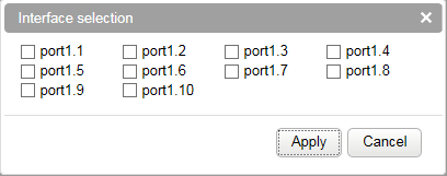
5.3 Backing up, clearing, or exporting observation data
Backup, clearing, and exporting of observation data is performed from [Management] - [Maintenance] - [Summary data management].
The Summary data management screen is shown below.
Summary data management screen (top page)
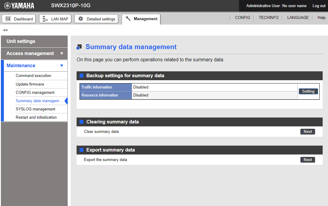
5.3.1 Observation data backup settings
Backup settings for observation data are performed from [Top page] - [Backup settings for summary data].
The screen that appears when you press the [Settings] button is shown below.
- Observation data backup settings screen
- Place a check mark in the check box of the summary data for which you want to enable backup, and then press the [Confirm] button.
After you press the button, the following screen appears.
- If you decide to cancel this setting, press the [Back] button in each screen.
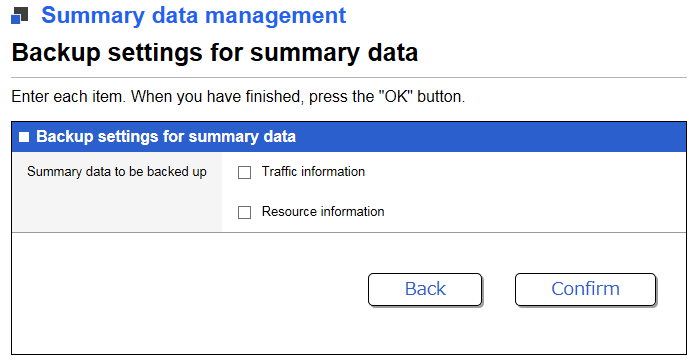
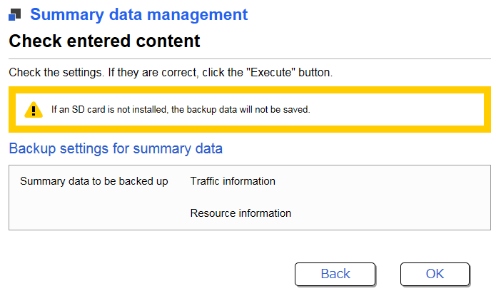
5.3.2 Clearing observation data
Clearing the observation data is performed from [Top page] - [Clearing summary data].
The screen that appears when you press the [Next] button is shown below.
- Clear observation data screen
- In the select box, choose the statistical data that will be cleared, and press the [Confirm] button. After you press the button, the following screen appears.
- If you decide to cancel this operation, press the [Back] button in each screen.
5.3.3 Exporting observation data
Exporting observation data is performed from [Top screen] - [Export summary data].
The screen that appears when you press the [Next] button is shown below.
- Observation data export screen
- From the select box, choose the observation data that you want to export to the PC that is accessing the Web GUI, and then specify the term of observation data that you want to export.
After making the selection, press the [OK] button, and the following screen will appear.
- If you decide to cancel this operation, press the [Back] button in each screen.
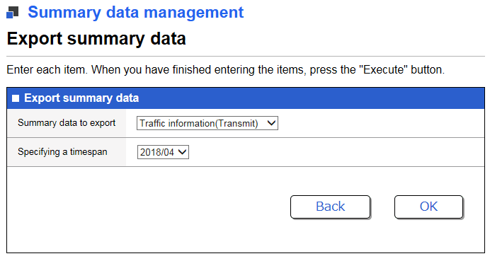
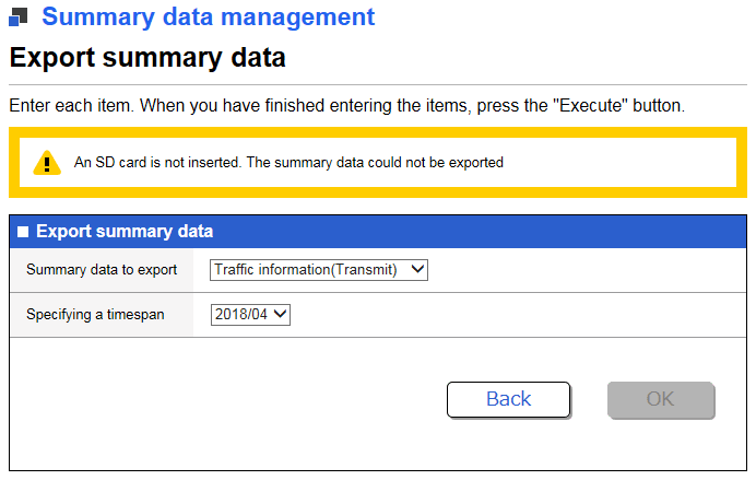
6 Points of Caution
None
7 Related Documentation
None
- SWX3220 Series Technical Data (Basic Functions)
- Maintenance and operation functions
- Scheduling function
Scheduling function
1 Function Overview
Scheduling functionality is used to execute specific processes when any particular time or event occurs.
This functionality enables the following types of actions using a Yamaha switch.
- Apply QoS to a specific VLAN only during a specific period.
- Supplies PoE power to wireless LAN access points only during the specified period.
- Periodically saves “tech-support” information in microSD memory.
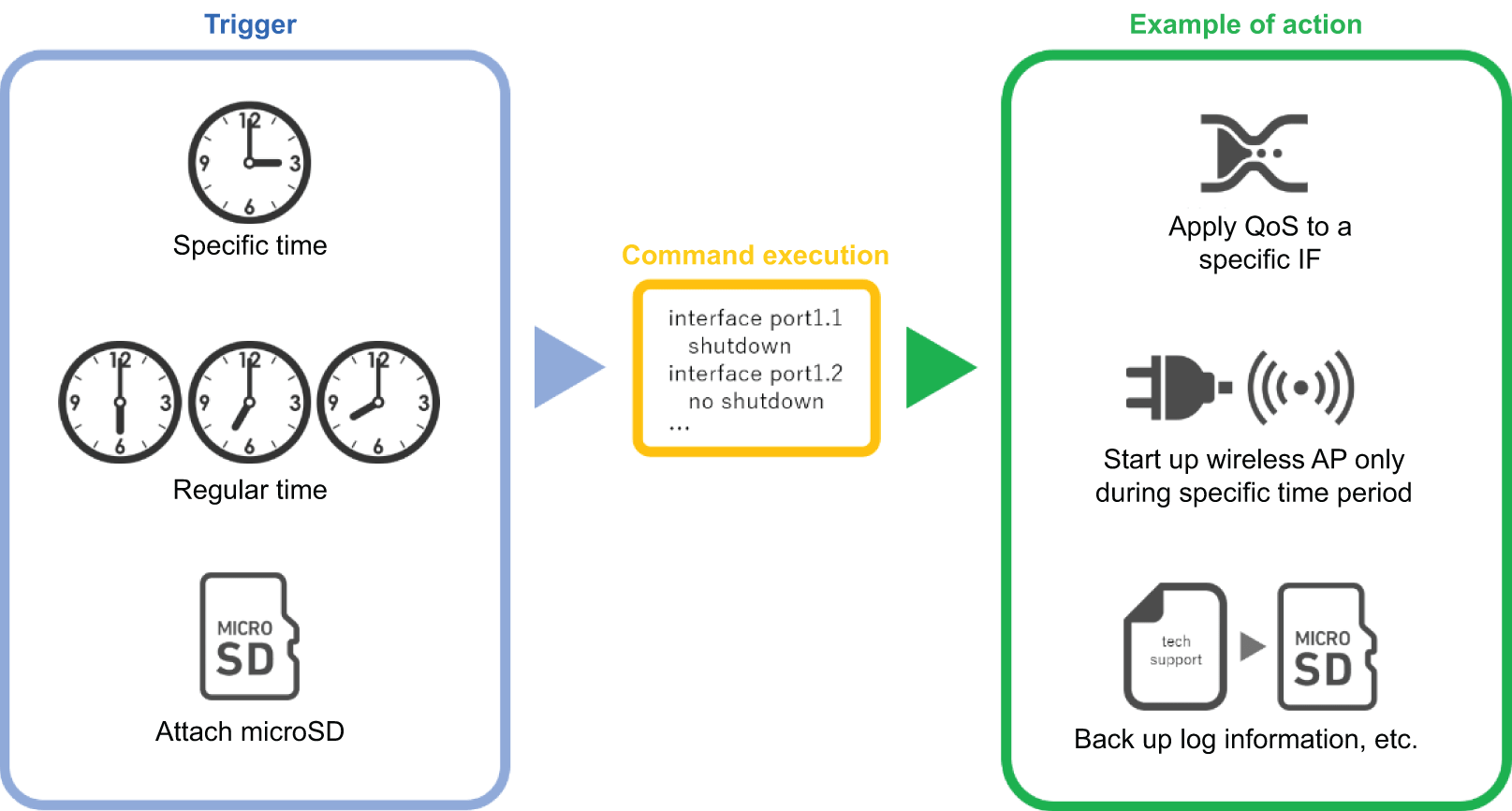
2 Definition of Terms Used
- Trigger
General term for conditions/criteria, such as that the internal clock time matches a specified time or that a specific event occurs.
- Time Trigger
Condition that the internal clock time matches a specified time.
- Event Trigger
Condition that a specific event occurs.
- Action
Action executed when a trigger is activated.
3 Function Details
Scheduling functionality involves specifying triggers and actions, which are the two parameter settings for executing specific process actions when a particular specified time or event trigger occurs.
3.1 Time Trigger
Time triggers can be specified in terms of year, month, day, hour, minute, and second.
Time triggers are specified using the schedule command.
Available setting parameters are indicated below.
| Type | Setting Method | Setting Value Example | |
|---|---|---|---|
| Date | Month 1 - 12 | One specific month (such as only December) | 12 |
| Multiple specific months (such as only January and February) | 1,2 | ||
| Range from specific month to December (such as February to December) | 2- | ||
| Range from specific month to specific month (such as February to July) | 2-7 | ||
| Range from January to specific month (such as January to July) | -7 | ||
| Every month | * | ||
| Day 1 - 31 | One specific day (such as day 1 only) | 1 | |
| Multiple specific days (such as days 1 and 2 only) | 1,2 | ||
| Range from specific day to last day (such as day 2 to month-end) | 2- | ||
| Range from specific day to specific day (such as days 2 to 7) | 2-7 | ||
| Range from day 1 to specific day (such as days 1 to 7) | -7 | ||
| Every day | * | ||
| Specific day-of-week only (such as Monday only) | mon | ||
| Multiple specific days of the week only (such as Saturday and Sundays only) | sat,sun | ||
| Range from specific day-of-week to specific day-of-week (such as Monday to Friday) | mon-fri | ||
| Range from Sunday to specific day-of-the-week (such as Sunday to Friday) | -fri | ||
| Hours, Minutes, Seconds | Hour 0 - 23 | Specific hour only (such as 23:00 only) | 23 |
| Multiple specific hours only (such as 01:00 and 22:00 only) | 1,22 | ||
| Range from specific hour to 23:00 (such as 02:00 to 23:00) | 2- | ||
| Range from specific hour to specific hour (such as 02:00 to 21:00) | 2-21 | ||
| Range from hour 00:00 to specific hour (such as 00:00 to 21:00) | -21 | ||
| Each hour | * | ||
| Minute 0 - 59 | One specific minute only (such as minute 59 only) | 59 | |
| Multiple specific minutes only (such as minutes 1 and 50 only) | 1,50 | ||
| Range from specific minute to minute 59 (such as minutes 2 to 59) | 2- | ||
| Range from specific minute to specific minute (such as minutes 2 to 50) | 2-50 | ||
| Range from minute 0 to specific minute (such as minutes 0 to 50) | -50 | ||
| Each minute | * | ||
| Second 0 - 59 | One specific second only (such as second 59 only) May be omitted | 59 | |
3.2 Event Triggers
Either of the following events can be specified as an event trigger.
Event triggers are specified using the schedule command.
Events that can be specified are indicated below.
| Type | Description |
|---|---|
| startup | Action is executed when startup occurs. |
| sd-attached | Action is executed when a microSD card is inserted. |
3.3 Actions
Processes executed when a time trigger or event trigger is activated are called actions.
To specify actions, use the schedule template command to switch to the schedule template mode and then specify the action using the cli-command command or script command.
The following two actions are available.
| Operation | Command for settings | Description |
|---|---|---|
| Execute Specified Commands | cli-command command | Execute the specified commands in ascending order of ID numbers. |
| Execute Specified Script | script command | Execute the character strings in the first 100 lines of the specified file /(model)/schedule/script.txt in external memory (microSD) as a command. |
4 Related Commands
Related commands are indicated below.
For details on the commands, refer to the Command Reference.
List of related commands
| Operating Mode | Command | Description |
|---|---|---|
| Global Configuration Mode | schedule | Specifies a schedule template ID that specifies the trigger and defines the action. |
| schedule template | Specifies the schedule template ID and switches to the schedule template mode. | |
| Schedule Template Mode | description | Specifies description of the schedule template. |
| action | Enables/disables schedule template Use disable to temporarily disable schedule function. | |
| cli-command | Defines command executed when trigger is activated. | |
| script | Enables execution of commands indicated in specified file in external memory. |
5 Setting Examples
5.1 Supplying PoE Power to Wireless LAN Access Points Only During Specified Hours
Supply PoE power to wireless LAN access points connected to port1.1 and port1.2 on weekdays only between 8:00 and 17:00.
Yamaha#
Yamaha# configure terminal
Yamaha(config)# schedule 1 time */mon-fri 8:00:00 1
Yamaha(config)# schedule template 1
Yamaha(config-schedule)# cli-command 1 configure terminal
Yamaha(config-schedule)# cli-command 2 interface port1.1-2
Yamaha(config-schedule)# cli-command 3 power-inline enable
Yamaha(config-schedule)# exit
Yamaha(config)#
Yamaha(config)# schedule 2 time */mon-fri 17:00:00 2
Yamaha(config)# schedule template 2
Yamaha(config-schedule)# cli-command 1 configure terminal
Yamaha(config-schedule)# cli-command 2 interface port1.1-2
Yamaha(config-schedule)# cli-command 3 power-inline disable
Yamaha(config-schedule)# end
Yamaha#
5.2 Obtaining Internal Information when microSD Memory is inserted
Automatically saves tech-support in microSD memory when microSD card is inserted.
Yamaha#
Yamaha# configure terminal
Yamaha(config)# schedule 1 event sd-attached 1
Yamaha(config)# schedule template 1
Yamaha(config-schedule)# cli-command 1 copy tech-support sd
Yamaha(config-schedule)# end
Yamaha#
6 Unavailable Commands
The following commands cannot be executed for the schedule function.
- backup system
- baudrate select
- boot prioritize sd / no boot prioritize sd
- certificate user
- Commands that begin with “clock”
- cold start
- copy radius-server local
- crypto pki generate ca / no crypto pki generate ca
- disable
- enable password
- exit
- firmware-update execute
- firmware-update sd execute
- logout
- Commands that begin with “ntpdate” or “no ntpdate”
- password / no password
- password-encryption / no password-encryption
- ping /ping6
- quit
- reload
- remote-login
- restart
- restore system
- schedule / no schedule
- schedule template / no schedule template
- Commands that begin with “show”
- ssh
- ssh-server host key generate
- Commands that begin with “stack” or “no stack”
- startup-config select / no startup-config select
- telnet
- traceroute / traceroute6
7 SYSLOG
The schedule function outputs the following syslog messages.
| Level | Output | Description |
|---|---|---|
| Info | [SCHEDULE]:inf:ID:X command is done | The schedule template ID:X command was executed when the trigger was activated. |
| [SCHEDULE]:inf:ID:X script is done | The schedule template ID:X script was executed when the trigger was activated. | |
| Error | [SCHEDULE]:err:ID:X cmd[ID][COMMAND] is prohibited to execute | Execution of the prohibited command COMMAND in schedule template ID:X was suppressed. |
| [SCHEDULE]:err:ID:X cmd[ID][COMMAND] is failed to execute | Command failed in schedule template ID:X due to invalid command format or in parameter setting. | |
| [SCHEDULE]:err:ID:X microSD is not mounted | Script execution failed at schedule template ID:X because microSD was not inserted. | |
| [SCHEDULE]:err:ID:X failed to get the schedule forlder path | Script execution failed at schedule template ID:X because the expected directory containing the script was not found. | |
| [SCHEDULE]:err:ID:X script is not found | Script execution failed at schedule template ID:X because the script file was not found. | |
| [SCHEDULE]:err:ID:X failed to add action to queue | Action failed at schedule template ID:X because action was discarded due to the many actions waiting for execution in the queue. |
8 Points of Caution
- When actions are executed, the cli-command executes actions in ascending ID number order.
- When actions are executed, even a command specified by the cli-command results in an execution error, the remaining commands are executed.
- If both a cli-command and script command are specified in the same schedule template, then the script command is executed and the cli-command is not executed.
- If multiple triggers are activated simultaneously, then actions are executed in ascending order of schedule template ID number.
- The following precautions apply for devices that include a stack.
- A “startup” event trigger is not activated in stack member switches.
- A “sd-attached” event trigger is not activated in stack member switches.
- The trigger is not activated if a stack is enabled and is in the standalone state.
- If the trigger activation time elapses due to the time setting being set manually by the clock set command or being changed by NTP, then any existing triggers scheduled to be activated within 59 seconds of when the current time setting was changed will be activated.
- If the trigger activation time was changed backward manually by the clock set command or by NTP, then the time triggers are checked again starting from the time to which it was set back.
- This function can be used to periodically save the configuration, but periodic rewriting will consume ROM capacity more quickly. ROM failures due to frequent rewriting are not warranted for free repairs, even if they occur during the warranty period.
9 Related Documentation
- None
- SWX3220 Series Technical Data (Basic Functions)
- Maintenance and operation functions
- Dante optimization setting function
Dante optimization setting function
1 Function Overview
Dante optimization settings is a function that makes it easy to specify the optimal environment for the Dante digital audio network.
This allows the user to easily make settings such as QoS settings, IGMP snooping settings, flow control disable settings, and EEE disable settings.
The following items can be set using the Dante optimization setting function.
| Object of setting | Function | Command |
|---|---|---|
| Entire system | Disable flow control | flowcontrol disable |
| Enable QoS | qos enable | |
| Optimize transmission queue by DSCP value | qos dscp-queue | |
| VLAN interface | Enable IGMP snooping | ip igmp snooping enable |
| Enable IGMP query transmission function | ip igmp snooping querier | |
| Set IGMP query transmission interval | ip igmp snooping query-interval | |
| Disable IGMP packet TTL value checking function | ip igmp snooping check ttl disable | |
| LAN/SFP port | Set QoS trust mode to DSCP | qos trust dscp |
| Disable flow control | flowcontrol disable | |
| Disable EEE | eee disable |
Use the Dante optimization setting function after you have made all of the basic switch settings (such as VLAN and IP).
If you make new changes to the settings, the Dante optimization settings will not follow.
2 Definition of Terms Used
- Dante
- A digital audio network specification developed by the Audinate Corporation.
3 Function Details
This function provides the following operations.
- Automatic optimization settings using LLDP
- Manual optimization settings via the Web GUI
3.1 Automatic optimization settings using LLDP
By receiving special LLDP frames from certain Dante-enabled devices made by Yamaha, optimal settings for using Dante can be automatically applied.
Automatic optimization settings via LLDP are set by the lldp auto-setting command.
By default, this product is set to enable automatic optimization settings via LLDP.
Certain Dante-enabled devices made by Yamaha transmit Yamaha-proprietary LLDP frames that include the following content.
- EEE (Energy-Efficient Ethernet) disable setting
- Flow control disable setting
- Diffserve base QoS setting
- IGMP snooping setting
If this function is enabled and the corresponding LLDP frame is received, the following settings are automatically applied to running-config.
[System-wide]
flowcontrol disable ... (Disable flow control)
qos enable ... (Enable QoS)
qos dscp-queue 0 0 ... (Set the DSCP-transmission queue ID conversion table; same for the following)
qos dscp-queue 1 0
qos dscp-queue 2 0
qos dscp-queue 3 0
qos dscp-queue 4 0
qos dscp-queue 5 0
qos dscp-queue 6 0
qos dscp-queue 7 0
qos dscp-queue 8 2
qos dscp-queue 9 0
qos dscp-queue 10 0
qos dscp-queue 11 0
qos dscp-queue 12 0
qos dscp-queue 13 0
qos dscp-queue 14 0
qos dscp-queue 15 0
qos dscp-queue 16 0
qos dscp-queue 17 0
qos dscp-queue 18 0
qos dscp-queue 19 0
qos dscp-queue 20 0
qos dscp-queue 21 0
qos dscp-queue 22 0
qos dscp-queue 23 0
qos dscp-queue 24 0
qos dscp-queue 25 0
qos dscp-queue 26 0
qos dscp-queue 27 0
qos dscp-queue 28 0
qos dscp-queue 29 0
qos dscp-queue 30 0
qos dscp-queue 31 0
qos dscp-queue 32 0
qos dscp-queue 33 0
qos dscp-queue 34 0
qos dscp-queue 35 0
qos dscp-queue 36 0
qos dscp-queue 37 0
qos dscp-queue 38 0
qos dscp-queue 39 0
qos dscp-queue 40 0
qos dscp-queue 41 0
qos dscp-queue 42 0
qos dscp-queue 43 0
qos dscp-queue 44 0
qos dscp-queue 45 0
qos dscp-queue 46 5
qos dscp-queue 47 0
qos dscp-queue 48 0
qos dscp-queue 49 0
qos dscp-queue 50 0
qos dscp-queue 51 0
qos dscp-queue 52 0
qos dscp-queue 53 0
qos dscp-queue 54 0
qos dscp-queue 55 0
qos dscp-queue 56 7
qos dscp-queue 57 0
qos dscp-queue 58 0
qos dscp-queue 59 0
qos dscp-queue 60 0
qos dscp-queue 61 0
qos dscp-queue 62 0
qos dscp-queue 63 0
[VLAN interface that received LLDP]
interface vlanX *Applies to the VLAN
  ip igmp snooping enable ... (Enable IGMP snooping)
  ip igmp snooping query-interval 30 ... (Set query transmission interval)
  ip igmp snooping querier ... (Set query)
  ip igmp snooping check ttl disable ... (Disable IGMP packet TTL value checking function)
[LAN/SFP port that received LLDP]
interface portX.X
  qos trust dscp ... (Set DSCP trust mode)
  flowcontrol disable ... (Disable flow control)
  eee disable ... (Disable EEE)
If you save using the copy running-config startup-config command or the write command, the settings are also applied to the startup-config that is used for the next and subsequent startups.
Even if the port to which the device is connected experiences a link-down state after automatic optimization settings, the automatically added settings are maintained.
This function can be used only for a physical interface (LAN/SFP port). It cannot be used with a link aggregated logical interface.
This does not apply to the trunk port.
In order to use this function, reception of LLDP frames must be enabled.
For this reason, check in advance that the following settings have been made.
- Use the lldp run command to enable the system-wide LLDP function.
- Use the lldp-agent command to create an LLDP agent for the applicable interface.
- Use the set lldp command to specify the LLDP frame transmit/receive mode.
With the default settings of this product, LLDP frame transmission and reception is enabled.
3.2 Manual optimization settings via the Web GUI
The Web GUI of this product allows you to manually specify Dante optimization settings and to enable/disable automatic settings using LLDP.
If manual settings are executed, the settings shown in 3.1 Automatic optimization settings via LLDP are specified for all LAN/SFP ports and VLAN interfaces.
In addition, the no shutdown command is set for the VLAN interface.
Dante optimization settings are performed from [Management] - [Dante optimization].
The Dante optimization screen is shown below.
Dante optimization screen (top page)
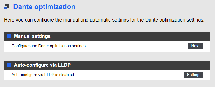
To execute manual settings, press the [Next] button for Manual settings.
To enable/disable automatic settings, press the [Setting] button for Automatic settings using LLDP.
3.2.1 Manual settings
The screen that appears when you press the [Next] button for Manual settings is shown below.
Manual settings - execution screen
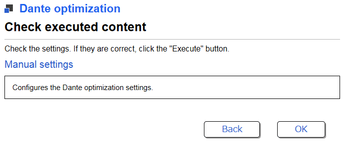
To execute manual settings, press the [OK] button.
3.2.2 Auto-configure via LLDP
The screen that appears when you press the [Setting] button for Auto-configure via LLDP is shown below.
Auto-configure via LLDP - execution screen
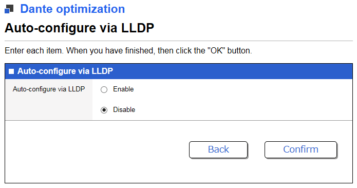
To enable/disable the automatic setting function using LLDP, select the [Enable] or [Disable] radio button, and then press the [Confirm] button.
The screen that appears when you press the [Confirm] button is shown below.
Auto-configure via LLDP - confirmation screen
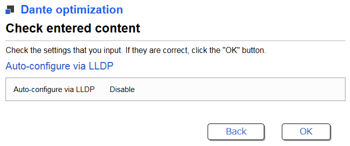
To enable/disable automatic settings using LLDP, press the [OK] button.
4 Related Commands
Related commands are shown below.
For details on the commands, refer to the Command Reference.
List of related commands
| Operations | Operating Commands |
|---|---|
| Set Dante automatic optimization settings function using LLDP | lldp auto-setting |
| Enable LLDP function | lldp run |
| Create LLDP agent | lldp-agent |
| Set LLDP transmission/reception mode | set lldp |
| Set flow control (system) | flowcontrol |
| Enable QoS | qos |
| Set DSCP - transmission queue ID conversion table | qos dscp-queue |
| Enable/disable IGMP snooping | ip igmp snooping |
| Set IGMP query transmission function | ip igmp snooping querier |
| Set IGMP query transmission interval | ip igmp snooping query-interval |
| Set IGMP packet TTL value checking function | ip igmp snooping check ttl disable |
| Set flow control (interface) | flowcontrol |
| Set QoS trust mode | qos trust |
| Set EEE | eee disable |
5 Examples of Command Execution
5.1 Automatic optimization settings using LLDP
Enable automatic optimization settings using LLDP.
Enable LLDP transmission and reception on port1.1.
Yamaha#configure terminal
Yamaha(config)#interface port1.1
Yamaha(config-if)#lldp-agent ... (Create LLDP agent and transition modes)
Yamaha(lldp-agent)#set lldp enable txrx ... (Set LLDP transmission/reception mode)
Yamaha(lldp-agent)#exit
Yamaha(config-if)#exit
Yamaha(config)#lldp run ... (Enable LLDP function)
Yamaha(config)#lldp auto-setting enable ... (Enable automatic optimization settings using LLDP)
6 Points of Caution
- Note that if you use this function when settings such as QoS settings, flow control settings, EEE settings, and IGMP snooping have already been made, those settings are overwritten by Dante-optimized settings.
- It is assumed that you will use the Dante optimization setting function after you have made all of the basic switch settings (such as VLAN and IP).
If you make new changes to the settings (such as adding a VLAN), the Dante optimization settings will not follow. - The setting values requested from Dante-enabled devices must be consistent between all devices. If the values are different, operation cannot be guaranteed.
- In general, IGMP snooping operates as version “3”.
7 Related Documentation
- SWX3220 Series Technical Data (Basic Functions)
- Maintenance and operation functions
- SDVoE setting optimization function
SDVoE setting optimization function
1 Function Overview
The SDVoE setting optimization function can be used to easily optimize settings for Software Defined Video over Ethernet (SDVoE).
More specifically, it enables users to easily specify multicasting settings and IGMP snooping settings.
The following settings can be set using the SDVoE setting optimization function.
| Object of setting | Function | Commands |
|---|---|---|
| Entire system | Set the method for processing unknown multicasting frames | l2-unknown-mcast |
| VLAN interface | Enable or disable IGMP snooping | ip igmp snooping |
| Set IGMP version | ip igmp snooping version | |
| Set IGMP snooping fast-leave | ip igmp snooping fast-leave | |
| Set IGMP query transmission function | ip igmp snooping querier | |
| Set IGMP query transmission interval | ip igmp snooping query-interval |
Use the SDVoE setting optimization function after all basic switch settings (such as VLAN and IP address settings) have been specified.
The SDVoE setting optimization function will not track new changes to settings.
2 Definition of Terms Used
- SDVoE
An AV standard for using software to transmit AV signals via an IP address.
3 Function Details
The function is available by clicking [Management] - [SDVoE optimization] in the Web GUI.
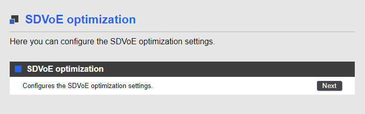
Press the Next button to display the execution screen.
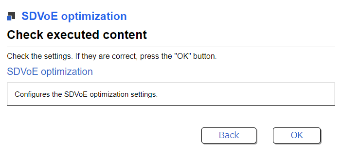
Press the Execute button to apply the settings optimized for SDVoE.
Executing the SDVoE setting optimization function will specify the following commands and save the settings.
- [System-wide]
l2-unknown-mcast discard ... (Discard multicasting frames not registered in the MAC address table)
- [VLAN interface]
interface vlanX Note: Applies to all enabled VLANs
  no shutdown                        ... (Enable VLAN interface)
  ip igmp snooping enable            ... (Enable IGMP snooping)
  ip igmp snooping version 2         ... (Specify IGMP version 2)
  ip igmp snooping fast-leave        ... (Enable IGMP snooping fast-leave)
  ip igmp snooping query-interval 60 ... (Set IGMP query interval to 60 seconds)
  ip igmp snooping querier           ... (Enable IGMPquery transmission function)
4 Related Commands
Related commands are indicated below.
For details on the commands, refer to the Command Reference.
List of related commands
| Operations | Operating commands |
|---|---|
| Set the method for processing unknown multicasting frames | l2-unknown-mcast |
| Enable/disable IGMP snooping | ip igmp snooping |
| Set IGMP version | ip igmp snooping version |
| Set IGMP snooping fast-leave | ip igmp snooping fast-leave |
| Set IGMP query transmission function | ip igmp snooping querier |
| Set IGMP query transmission interval | ip igmp snooping query-interval |
5 Points of Caution
- This function cannot be used if the stack function is enabled.
- Note that if this function is used while IGMP snooping or other settings are specified, the SDVoE setting optimization function will overwrite those settings.
- The SDVoE setting optimization function assumes all other basic switch settings (such as VLAN and IP address settings) have already been specified.
If new changes were made (such as additional VLANs), the optimized SDVoE settings are not tracked.
6 Related Documentation
Stack function
1 Function Overview
A stack is a function that connects multiple switches and operates as a single virtual switch.
The features of the stack are shown below.
Realization of highly efficient redundancy
There are two methods for removing single points of failure (SPOF) in the network configuration: the method composed of VRRP and STP, and the method composed of stack and link aggregation.
By using the stack, unlike VRRP, there is no standby switch, so you can increase the usage efficiency of the switch while ensuring redundancy.
Easy port expansion
You can easily increase the number of available ports by adding switches.
Stack overview
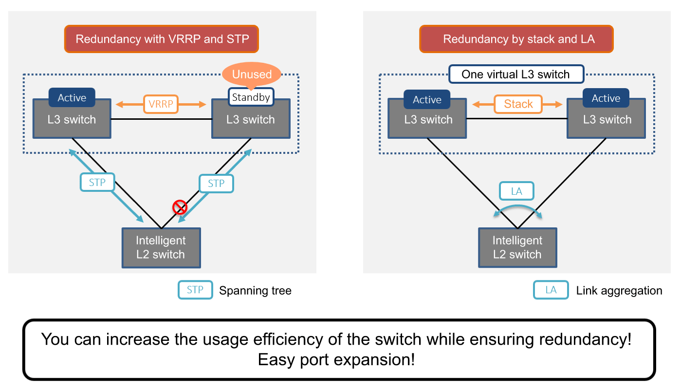
The stack function is disabled when shipped from the factory.
2 Definition of Terms Used
- Member switch
Network switches that make up the stack.
Each switch is identified by a stack ID.
- Stack ID
An ID that identifies the member switches that make up the stack.
The stack ID can be set from 1 to the maximum number of stacks that can be configured (currently 2).
- Main switch
The main switch is selected from among member switches for managing other member switches.
Given default settings, the switch with stack ID 1 operates as the main switch.
- Virtual switch
A single logical switch consisting of multiple member switches using the stack function.
- Stack port
SFP+ slot used to connect the network switches that make up the stack.
- Stack link
A connection between member switches that make up a stack.
3 Function Details
3.1 Stack configuration
The configurations that can be stacked for each model are shown below.
Only two units of the same model are supported.
Note that the stack must be configured with two stack links in order to reduce the impact of failure.
SWX2320-16MT stack configuration
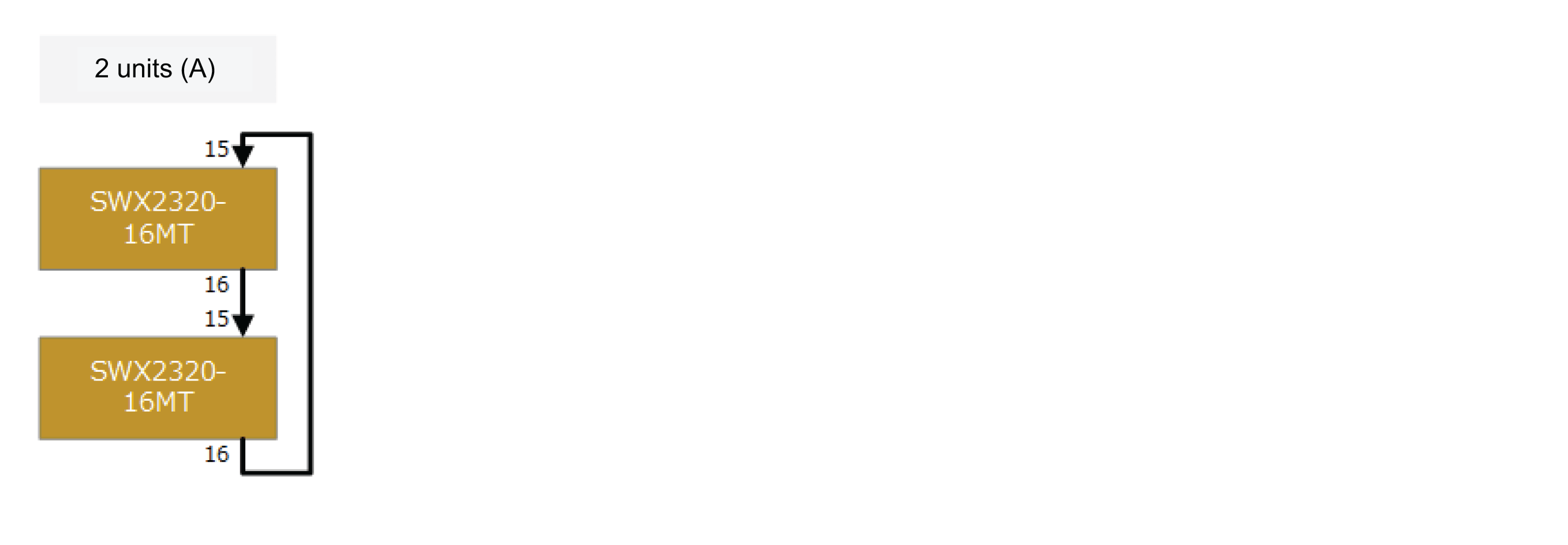
SWX2322P-16MT stack configuration
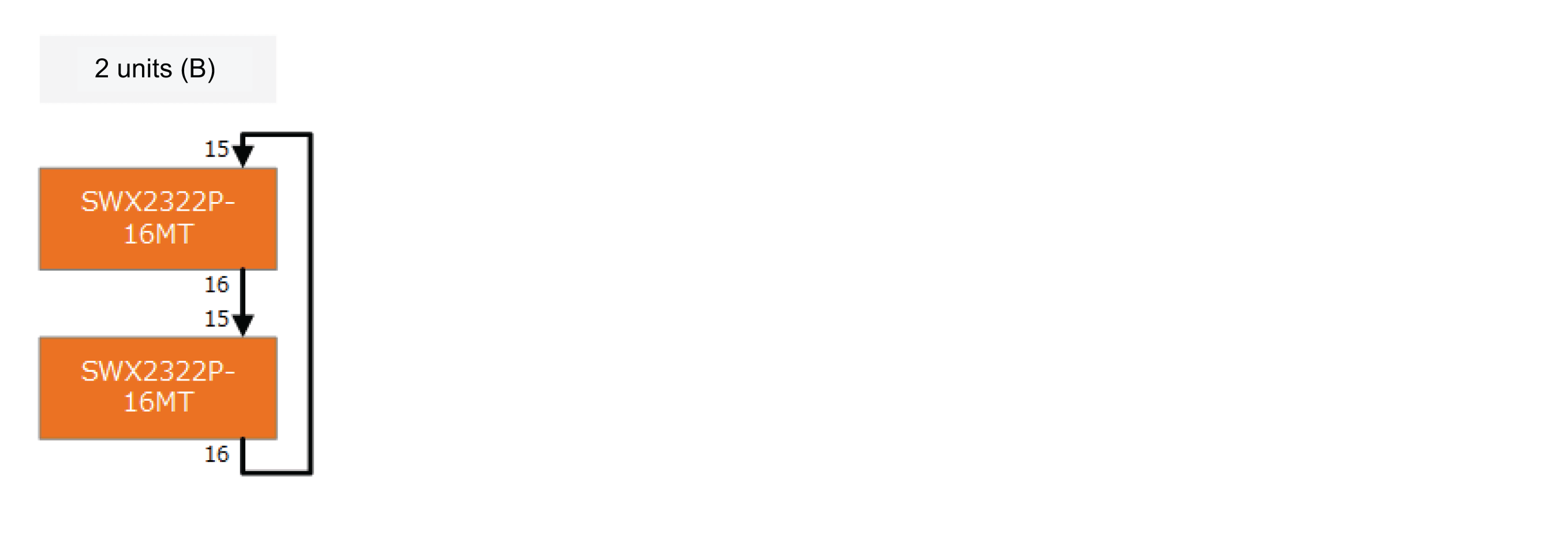
SWX3220-16MT stack configuration
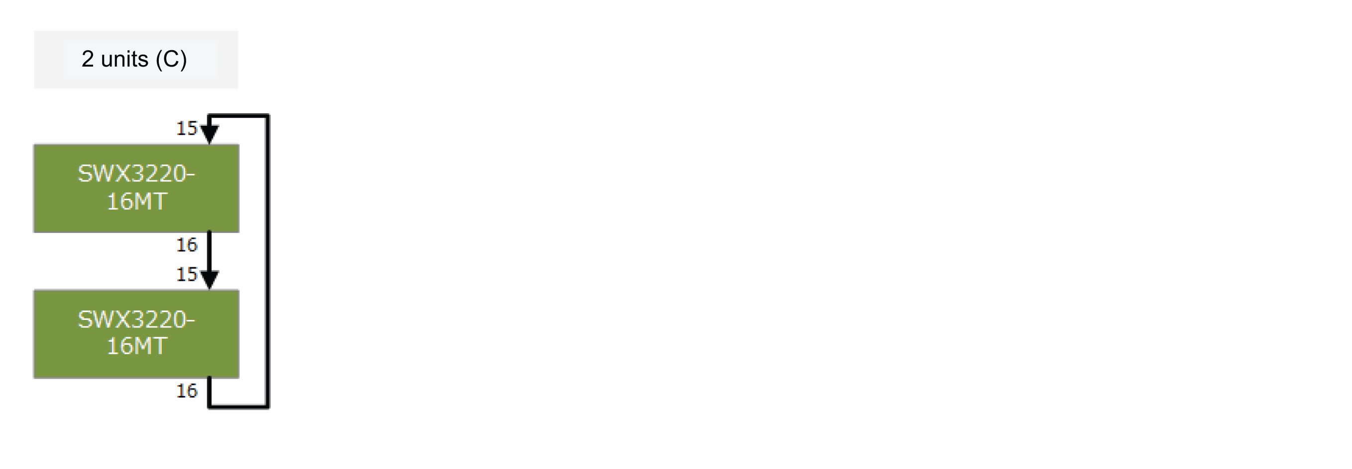
SWX3220-16TMs stack configuration
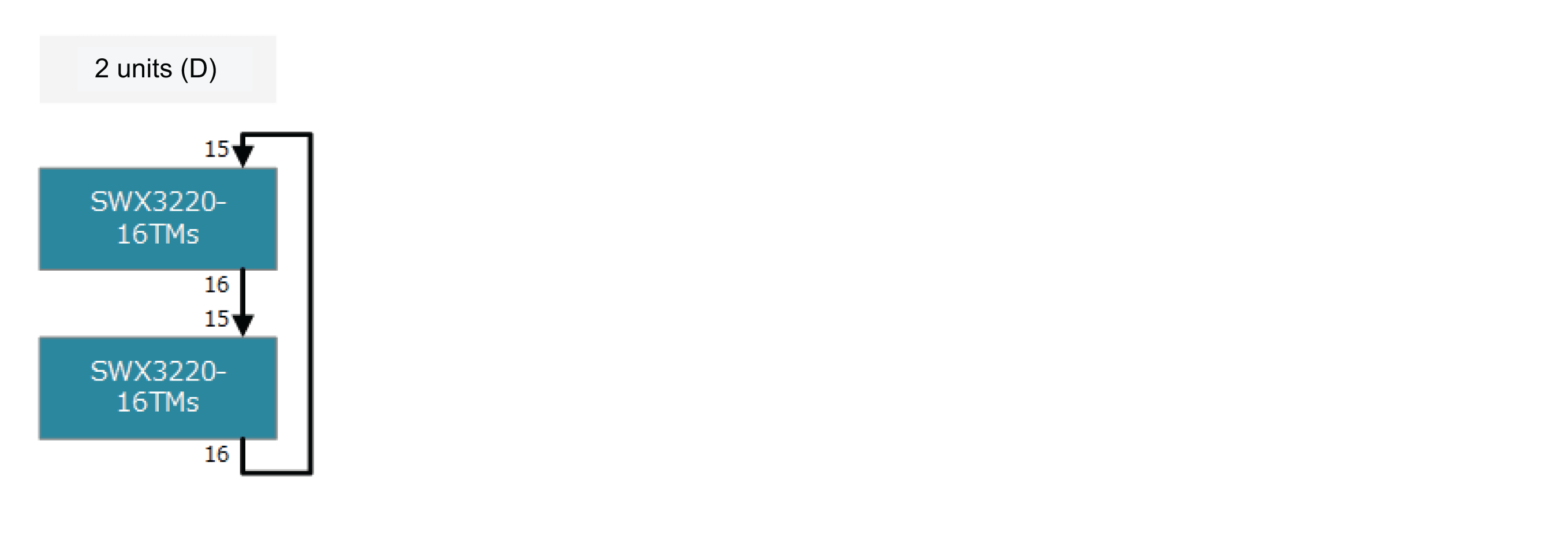
3.2 Connection between member switches
When the stack function is enabled, the following SFP+ slots are switched to stack ports as connecting ports between members.
- SWX2320-16MT: ports 15, 16
- SWX2322P-16MT: ports 15,16
- SWX3220-16MT: ports 15, 16
- SWX3220-16TMs: ports 15,16
Unlike normal communication ports, stack ports are used only for communication between member switches.
Connection between member switches is only possible with the direct attach cable (YDAC-10G-1M/3M) or SFP+ module (YSFP-10G-SR/LR) provided by Yamaha.
When connecting with another company’s product, the stack link will be forced down.
The stack port to be connected connects the lower number port and the higher number port of the member switch.
3.3 Main switch selection and MAC address assignment
The main switch selection and MAC address assignment rules are shown below.
Note that the MAC address used in the stack configuration is applied according to the following rules in order to eliminate the impact on communication.
- In the default stack configuration, the MAC address of the main switch (switch with ID 1) is used as the MAC address for the virtual switch.
- If a member switch other than the main switch is disconnected (due to an error) during stack configuration, then the virtual switch will continue to use the specified MAC address.
- If the main switch is disconnected (due to an error) during stack configuration, the virtual switch will continue to use the specified MAC address.
In other words, the MAC address of the switch that is not included in the stack configuration is used.
- Even when a switch other than the failed switch (a switch with a different MAC address) is installed as a member switch, the virtual switch continues to use the configured MAC address.
If you want to reconfigure the stack with the current configuration status, restart the virtual switch at the same time to perform reconstruction.
(The stack with ID 1 becomes the main switch and the virtual switch uses the MAC address of the main switch.)
Main switch selection and MAC address assignment
| No | Stack configuration | Main switch selection rule | |
|---|---|---|---|
| 1 | Initial composition | 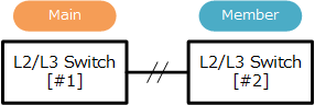 | The stack with ID 1 specified is selected as the main switch. At this time, the MAC address of stack ID 1 is used as the virtual switch MAC address. |
| 2 | Fault occurrence | 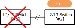 | If an error occurs in the main switch, the member switch with the smallest stack ID number is selected as the main switch. At this time, the virtual switch MAC address retains the MAC address of stack ID 1. |
| 3 | Abnormal state recovery | 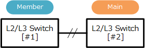 | If a switch with a failure is reinstalled in the stack, the switch currently selected as the main switch will continue to function as the main switch. At this time, the virtual switch MAC address retains the MAC address of the faulty stack ID 1. |
3.4 Operations on virtual switches
Operations on virtual switches in a stack configuration are basically controlled from the master switch.
The specifications related to operation are shown below.
- Logging in to a virtual switch always logs into the main switch.
If necessary, the remote-login command can be used to log into another member switch.- Prompt when logging in to main switch
Yamaha>
- Prompt when logging in to member switch
Yamaha-2> ... (Stack ID is displayed after the host name)
- Prompt when logging in to main switch
- The configuration (running-config, startup-config) for the virtual switch is always synchronized between member switches.
After completing the configuration, be sure to save running-config with the write command.
The write command can only be executed from the main switch side.
- When operating a virtual switch, the information stored in the L2 network switch (e.g. FDB learning information, ARP cache, etc.) is automatically synchronized.
There is no need for the user to be aware of this.
- Use the show logging command to show logging for the virtual switch after logging in.
In that state, the log shown is for the main switch. To view the log for a member switch, use the remote-login command to log into the applicable member switch and view the corresponding log.
3.5 Switch status when stacking
The member switch manages the status in the stack configuration as follows.
This state can be shown using the show stack command.
Setting
- A state in which one or more stack port links are up, and the settings necessary for stacking between member switches are performed.
Specifically, the configuration is automatically ascertained between member switches.
- A state in which one or more stack port links are up, and the settings necessary for stacking between member switches are performed.
Active
- A state in which automatic recognition of the configuration between member switches is completed, various settings are synchronized, and virtualization is performed by multiple member switches.
Virtualization is performed by two or more switches.
- A state in which automatic recognition of the configuration between member switches is completed, various settings are synchronized, and virtualization is performed by multiple member switches.
Inactive
- A state in which a failure has occurred and the virtual switch has been removed.
All communication ports including the stack port are forcibly shut down and communication cannot be established. (Closed state)
- A state in which a failure has occurred and the virtual switch has been removed.
Standalone
- The stack function is enabled, but since negotiation cannot be performed with the member switch, it is operating on one unit.
Transition to this state occurs when there is no opposing switch temporarily, such as during initial installation.
In this state, the stack ID that has been set must be enabled, so it is operated with the set ID.
- The stack function is enabled, but since negotiation cannot be performed with the member switch, it is operating on one unit.
Standalone(separated)
- Same status as Standalone status indicated above.
However, it remembers that a stack was once configured, so it retains main switch selection information that can be used when reconfiguring the stack.
- Same status as Standalone status indicated above.
Disable
- The stack function is disabled.
In this state, the stack ID is forcibly operated at 1. (Even if the stack ID is set to other than 1)
- The stack function is disabled.
3.6 Detection and measures for abnormal conditions
When a member switch in the stack configuration detects an error, it tries to resolve it autonomously within the virtual switch so that the network service is not affected.
This switch monitors the following abnormal conditions.
Abnormality detection on the local node
- Does not meet stack configuration conditions (stack ID error, firmware version error)
- Stack link error (down detection)
- Fan stopped
- Voltage value error
- Current value error
Connection node error detection
- Heartbeat frame reception timeout
Heartbeat is a function to check whether member switches are operating normally.
If the heartbeat frame is not received for a certain period (currently 4 seconds), it is determined that an error has occurred in the member switch.
The operation when an error is detected is shown below.
Operation when fault is detected
| Detected node | Detected content | Operation after detection | State after detection | Remarks | |
|---|---|---|---|---|---|
| Main switch | Setting error | Abnormal stack ID or firmware version | As a virtual switch, it is determined that processing cannot be continued, and the network port and stack link are forcibly taken down and disconnected from the stack configuration. | Inactive | |
| Stack link down | One of the two links down | The status as the main switch is maintained, but two-way communication is achieved via one link. | Active | ||
| Both links down | The status as the main switch is maintained. | Standalone (separated) | Possible double-main status | ||
| HW error | Fan stopped due to voltage/current value error | In this state, it is determined that the switch cannot continue to be treated as the main switch, so the network ports and stack links are forcibly disabled to disconnect the switch from the stack configuration. | Inactive | ||
| Heartbeat error | Notifications from member switches stopped | Continues to be operated as the main switch. | Standalone (separated) or Active | If there is only one remaining configuration, Standalone (separated) | |
| Member switch that is not the main switch | Setting error | Abnormal stack ID or firmware version | As a virtual switch, it is determined that processing cannot be continued, and the network port and stack link are forcibly taken down and disconnected from the stack configuration. | Inactive | |
| Stack link down | One of the two links down | The member switch status is maintained, but two-way communication is achieved with one switch. | Active | ||
| Both links down | Upgraded to the main switch to continue service. | Standalone (separated) | Possible double-main status | ||
| HW error | Fan stopped due to voltage/current value error | As a member switch, it is determined that processing cannot be continued, and the network port and stack link are forcibly taken down and disconnected from the stack configuration. | Inactive | ||
| Heartbeat error | Notifications from the main switch stopped | Upgraded to the main switch to continue service. | Standalone (separated) or Active | If there is only one remaining configuration, Standalone (separated) | |
4 Related Commands
Related commands are shown below.
For details, refer to the Command Reference.
List of stack related commands
| Operations | Operating Commands |
|---|---|
| Setting stack functions | stack |
| Changing the stack ID number | stack renumber |
| Setting the IP address range used for stack ports | stack subnet |
| Show stack information | show stack |
5 stack initial settings
The initial setting flow for stack configuration is shown below.
- Preparation of necessary equipment
- Member switch settings
- Connecting member switches
5.1 Preparation of necessary equipment
Prepare the equipment necessary to configure the stack.
Member switch
Prepare member switches for stack configuration.
For the stackable configuration, refer to 3.1 Stack configuration.
Stack port connection cable
Determine and prepare the interface to which the member switches are connected.
Use direct attach cables when configuring the stack in a rack, and SFP+ modules when a certain distance is required such as between floors or buildings.
For details, refer to 3.2 Connection between member switches.
External memory (SD card)
It is recommended to use external memory to save backup data such as configs and logs during stack operation.
By using external memory, you can use it to recover the config if a failure occurs.
5.2 Member switch settings
Set the member switches that constitute the stack.
Consider the following before you begin configuration.
Determine the stack IDs assigned to the member switches
The stack IDs assigned to the member switches must be determined statically.
Given default settings, the switch with stack ID 1 will be operated as the main switch.
Determine the startup config save destination
Determine the save destination for the startup config during stack configuration.
Select the config ID in the flash ROM as the save destination and make it clear that it is to be used for saving the stack in the description.
After reviewing, configure member switches individually as follows.
Activate member switches
Start the member switches individually and access them from the serial console.
Check and update firmware version
Check the current firmware version with the show environment command.
Yamaha> show environment
SWX3220-16MT BootROM Ver.1.00
SWX3220-16MT Rev.4.02.XX (Fri Jan  1 00:00:00 2021) ... (Check firmware version)
main=SWX3220-16MT ver=00 serial=Z0000000XX MAC-Address=ac44.f200.0000
...
Check the latest public firmware on Rt pro.
If the public firmware version of the relevant switch is newer than the firmware that is running, update it.- It is recommended that member switches be updated to the latest firmware with improvements made to known issues.
- By default, Firmware update using an SD card is enabled.
Refer to Firmware update for how to update using an SD card.
Set the save destination for startup config
Use the startup-config select command to select the config to be used during stack operation.
At this time, it is recommended to set the description to use for the config during stack operation.
Yamaha> enable
Yamaha# startup-config description 1 Stack ... (Set “Stack” and the description in startupconfig#1)
Yamaha# startup-config select 1 ... (Select startup-config#1)
reboot system? (y/n): y  ... (Reboot)
Stack ID settings
Check the switch status with show stack and confirm that the stack function is disabled.
Also check the stack ID. The initial value of the stack ID is set to 1.
Yamaha> enable
Yamaha#
Yamaha# show stack
Stack: Disable

Configured ID        : 1
Subnet on stack port : Auto-ip
Virtual MAC-Address  : 00a0.de00.0000

ID  Model          Status      Role     Serial       MAC-Address
------------------------------------------------------------------------

Interface    Status
------------------------------------------------------------------------

Yamaha#
If necessary, change the stack ID using the stack renumber command.Yamaha(config)# stack 1 renumber 2 ... (Change the stack ID number from #1 to #2) Yamaha(config)# do show stack Stack: Disable Configured ID : 2 Subnet on stack port : Auto-ip Virtual MAC-Address : 00a0.de00.0000 ID Model Status Role Serial MAC-Address ------------------------------------------------------------------------ Interface Status ------------------------------------------------------------------------ Yamaha#
Enabling the stack function
Use the stack enable command to enable the stack function.
After entering the command, reboot the device.
After the reboot is complete, default-config is applied.
Yamaha(config)#stack enable ... (enable stack function)
reset configuration and reboot system? (y/n): y ... (execute reboot)
After rebooting, check the switch status with show stack and confirm that the stack function is enabled.
Also check the save destination of the startup config.Yamaha> enable Yamaha# Yamaha# show stack Stack: Enable ... (Stack function is enabled) Configured ID : 1 Running ID : 1 Status : Standalone Subnet on stack port : Auto-ip Virtual MAC-Address : 00a0.de00.0000 ID Model Status Role Serial MAC-Address ------------------------------------------------------------------------ 1 SWX3220-16MT Standalone Main Z0000000XX 00a0.de00.0000 ... (Standalone units operated as a single unit are operated as the main unit) Interface Status ------------------------------------------------------------------------ port1.15 down port1.16 down Yamaha>show environment SWX3220-16MT BootROM Ver.1.00 SWX3220-16MT Rev.4.02.XX (Fri Jan 1 00:00:00 2021) main=SWX3220-16MT ver=00 serial=Z0000000XX MAC-Address=ac44.f200.0000 CPU: 7%(5sec) 8%(1min) 8%(5min) Memory: 11% used Fan status: Normal Fan speed: FAN1=3174RPM FAN2=3220RPM FAN3=3187RPM Startup firmware: exec1 Startup Configuration file: config1 ... (Confirm that the set startup config is applied) selected file: config1 Serial Baudrate: 9600 Boot time: 2021/01/23 17:41:34 +09:00 Current time: 2021/01/29 16:25:57 +09:00 Elapsed time from boot: 5days 22:44:41 Temperature status: Normal Temperature: 40 degree C
5.3 Connecting member switches
Connect the enabled switches to the stack using a direct attach cable or SFP+ module.
Refer to 3.2 Connection between member switches for the connection method.
The member switches can be connected with the power turned off or the power turned on.
After connecting the member switches, check the system status using the show stack command.
Yamaha# show stack
Stack: Enable

Configured ID        : 1
Running ID           : 1
Status               : Active
Subnet on stack port : Auto-ip
Virtual MAC-Address  : 00a0.de00.0000

ID  Model          Status      Role     Serial       MAC-Address
------------------------------------------------------------------------
1   SWX3220-16MT   Active      Main     Z0000000XX   00a0.de00.0000
... (The switch with stack ID 1 operates as the main switch)
2   SWX3220-16MT   Active      Member    Z0000000XX   00a0.de00.0000
... (The switch with stack ID 2 operates as a member switch)

Interface    Status
------------------------------------------------------------------------
port1.15     up
port1.16     up
port2.15     up
port2.16     up
Use the backup system command to back up the initial setting status of the member switch to the SD card.
By saving swx3220.bin (firmware file) in the /swx3220/firmware folder in the SD card, both settings and firmware can be backed up during backup execution.
Yamaha> enable
Yamaha# backup system  ... (Copies all main switch settings to the SD card)
Succeeded to backup system files and firmware file.
Yamaha# remote-login 2 ... (Logs in remotely to the member switch (stack ID: 2))

Entering character mode
Escape character is '^]'.

SWX3220-16MT Rev.4.02.XX (Fri Jan  1 00:00:00 2021)
  Copyright (c) 2018-2021 Yamaha Corporation. All Rights Reserved.

Yamaha-2> enable
Yamaha-2# backup system  ... (Copies all member switch (stack ID: 2) settings to the SD card)
Succeeded to backup system files and firmware file.
This completes the initial stack settings.
Install the virtual switch in the network to be used and perform the settings required for operation.
After completing the settings required for operation, backup should be performed in case of an abnormality, just as with the initial settings.
6 Exchanging member switches
This section describes the exchange procedure when an error occurs in a member switch in a configuration that uses two SWX3220-16MTs.
The following shows each case of using and not using an SD card.
6.1 Exchange procedure using an SD card
Member switches are exchanged by backup/restore using an SD card.
Exchange procedure
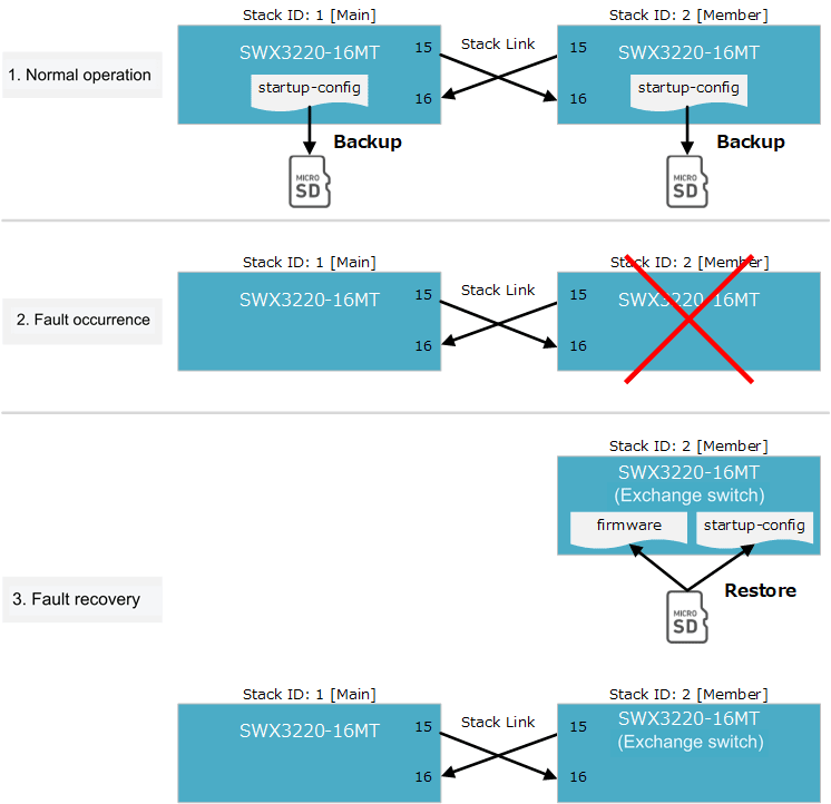
During normal operation
After completing the setting to the member switches, back up the system information to the SD card in consideration of failure.
To back up system information, execute the backup system command.
Before performing backup, save swx3220.bin (firmware file) in the /swx3220/firmware folder on the SD card to back up the firmware.
Fault occurrence
The following assumes a fault occurred in the member switch with stack ID: 2.
Fault recovery
Prepare the member switches to be exchanged and connect the SD card that contains the backup of the failed switches.
Apply the firmware and system information by executing the restore system command.
After it is applied, restore the stack configuration by turning off the power, connecting it to the main switch currently operating, and then turning on the power.
6.2 Exchange procedure without using an SD card
Exchange the member switches without using an SD card.
At the start of operation
After installation of the member switches is completed, store the same revision firmware as the firmware written in the member switches on a PC, etc.
Record the serial number, config ID being used, and stack ID of each member switch.
Yamaha> show environment
SWX3220-16MT BootROM Ver.1.00
SWX3220-16MT Rev.4.02.XX (Fri Jan  1 00:00:00 2021)
main=SWX3220-16MT ver=00 serial=Z0000000XX MAC-Address=ac44.f200.0000   ... (Serial number)
CPU:   7%(5sec)   8%(1min)   8%(5min)    Memory:  11% used
Fan status: Normal
Fan speed: FAN1=3174RPM FAN2=3220RPM FAN3=3187RPM
Startup firmware: exec1
Startup Configuration file: config1   ... (config ID)
             selected file: config1
Serial Baudrate: 9600
Boot time: 2021/01/23 17:41:34 +09:00
Current time: 2021/01/29 16:25:57 +09:00
Elapsed time from boot: 5days 22:44:41
Temperature status: Normal
Temperature: 40 degree C

Yamaha> show stack
Stack: Enable

Configured ID        : 1  ... (Stack ID)
Running ID           : 1
Status               : Active
Subnet on stack port : Auto-ip
Virtual MAC-Address  : 00a0.de00.0000

ID  Model          Status      Role     Serial       MAC-Address
------------------------------------------------------------------------
1   SWX3220-16MT   Active      Main     Z0000000XX   00a0.de00.0000
2   SWX3220-16MT   Active      Member   Z0000000XX   00a0.de00.0000

Interface    Status
------------------------------------------------------------------------
port1.15     up
port1.16     up
port2.15     up
port2.16     up
Fault occurrence
The following assumes a fault occurred in the member switch with stack ID: 2.
Fault recovery
Prepare the member switches to be exchanged and write the saved firmware.
Start the member switches and change the config ID used at startup.
* If the config ID used at the start of operation is 0, there is no need to change it.
Yamaha> enable
Yamaha# startup-config select 1
reboot system? (y/n): y
After rebooting, enable the stack function.
For the stack ID to be set, refer to the member switch serial number and stack ID recorded at the start of operation.Yamaha> enable Yamaha# configure terminal Yamaha(config)# stack 1 renumber 2 ... (Set stack ID 2) Yamaha(config)# stack enable ... (Enable stack function) reset configuration and reboot system? (y/n): y
After enabling the stack function, restore the stack configuration by turning off the power, connecting the switch to the switch functioning as the main switch, and then turning on the power.
7 Firmware update
The following two methods are provided for updating the firmware during stack configuration.
- Method to update member switches during configuration simultaneously (parallel update)
- Method to update without stopping network services (sequential update)
Parallel update is an effective method if you have enough time to allow a service outage.
However, during stack configuration, it is recommended to perform a sequential update without service interruption.
Note that firmware updates during stack configuration are supported only for the following.
- Update by sending update firmware using tftp client or Web GUI
- Using an SD card to update the firmware
If the firmware is updated while the SD card is inserted, SD card boot may be performed when restarting.
You can disable SD card boot with the boot prioritize sd command.
Yamaha> enable
Yamaha# boot prioritize sd disable   ... (Disable SD card boot)
reboot system? (y/n): y
For details, refer to Firmware update.
7.1 Firmware parallel update
Firmware parallel update updates the firmware of the member switches in the stack configuration at the same time.
The service will be stopped because the entire virtual switch is restarted for the update.
Note the following points when performing parallel update.
- Confirm that the firmware update method is set to normal (firmware-update reload-method command)
- Confirm that the firmware update application time is set to the set time (firmware-update reload-time command)
An overview of parallel update is shown below.
Parallel update process flow
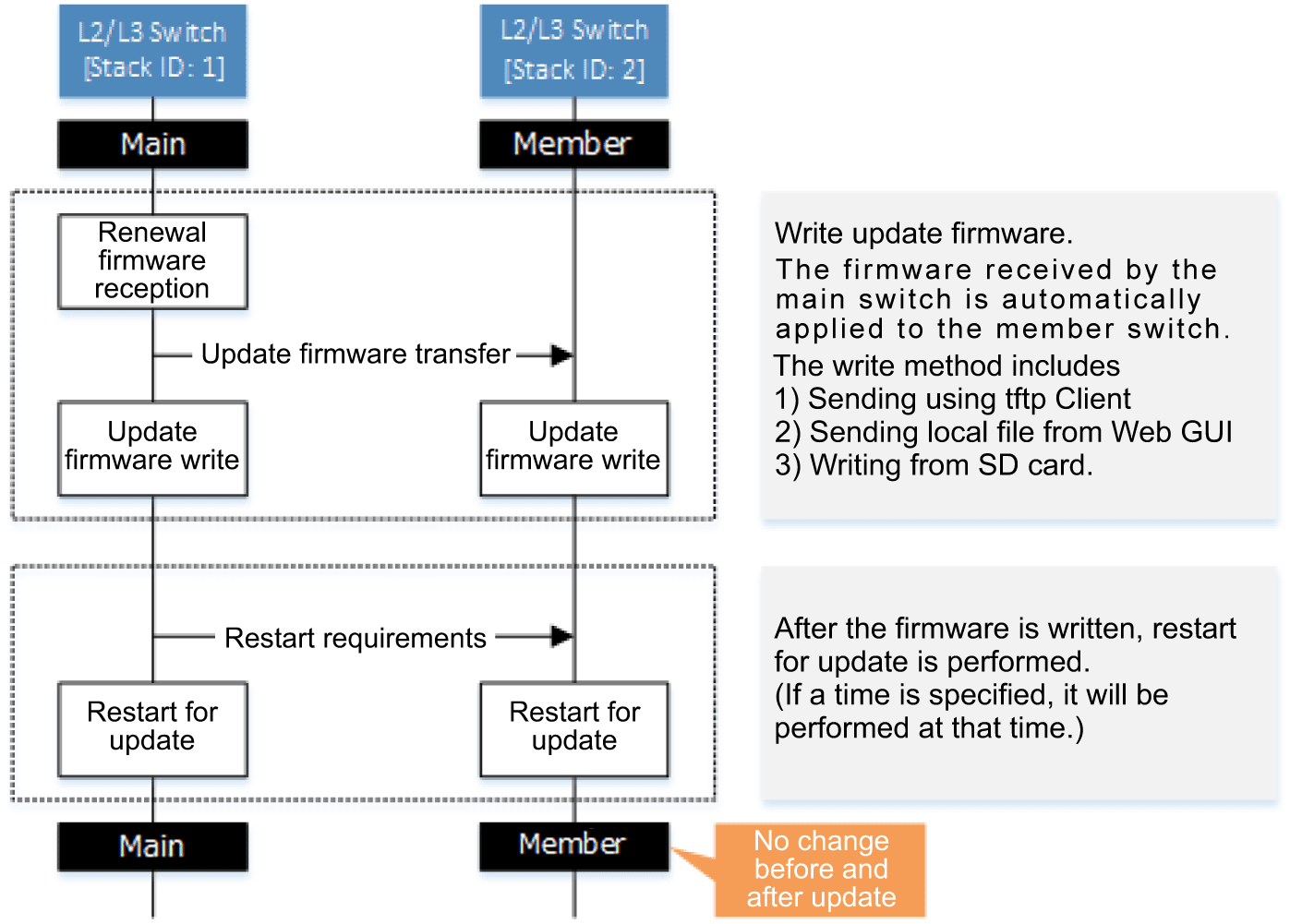
7.2 Firmware sequential update
Firmware serial update updates the firmware of the member switches in the stack configuration sequentially.
The service will not be stopped because the entire virtual switch is not restarted for the update. (* See Points of Caution 6)
Note the following points when performing sequential update.
- Confirm that the firmware update method is set to sequential (firmware-update reload-method command)
- Confirm that the firmware update application time is set to the set time (firmware-update reload-time command)
An overview of sequential update is shown below.
Sequential update process flow
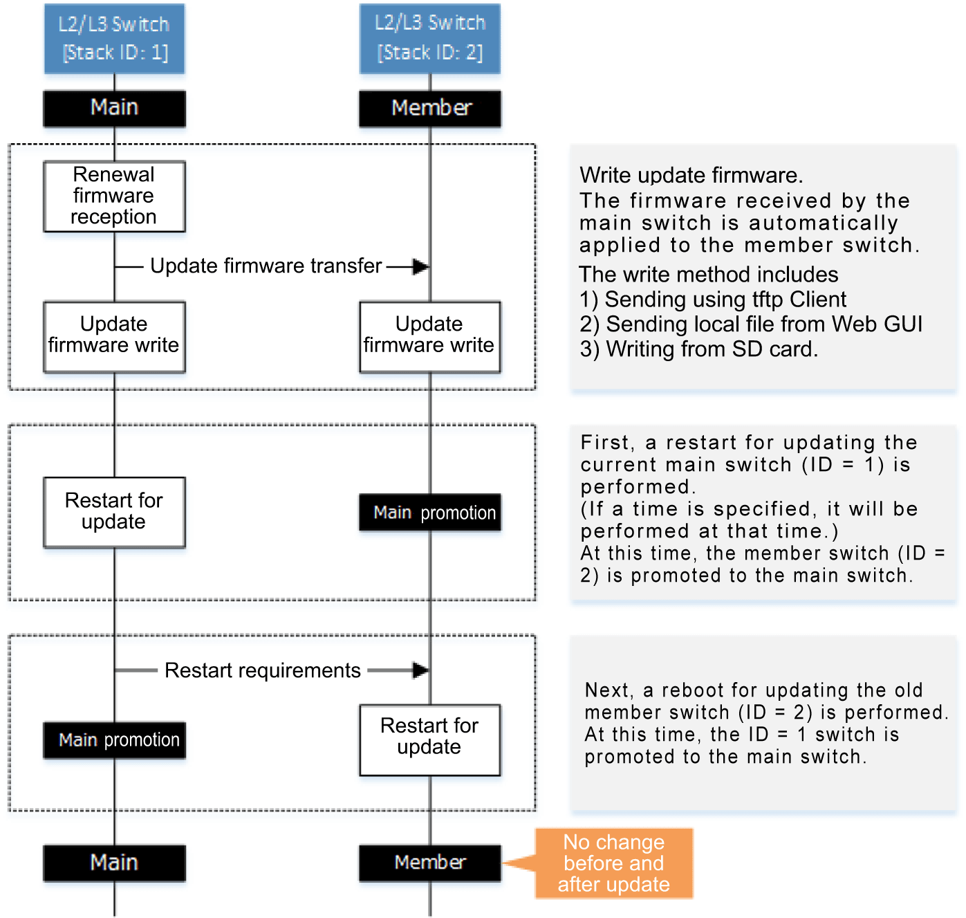
8 Points of Caution
- When the stack function is enabled, the following functions cannot be used.
- RMON
- IPv6
- VRRP
- MLD snooping
- PTP
- When the stack function is enabled, it can be used as a function, but some restrictions occur.
- Mirroring function
- Mirroring between member switches is not possible.
- Flow control
- Pause frame cannot be transmitted.
- Back pressure function
- When communicating via the stack port, jam signals are not transmitted.
- SFP optical reception level monitoring
- The optical reception level of the stack port is not monitored.
- Link aggregation
- The maximum number of logical interfaces is reduced by one.
- Command line input
- The users who can transition to global configuration mode are limited.
When the console side is in global configuration mode and the telnet side transitions to global configuration mode, the console side automatically transitions to privileged EXEC mode.
Console, telnet, ssh, remote login, and GUI settings are exclusively controlled.
- It is not possible to log in from the main switch and other member switch consoles at the same time.
- The users who can transition to global configuration mode are limited.
- DHCP client
- If the stack function is enabled and the Auto IP function is used on the stack port, the DHCP client cannot be used.
- startup-config select command
- Do not use the startup-config select command while the stack is configured. It may become impossible to configure correctly.
To switch the config using the startup-config select command, disconnect the direct attach cable and cancel the stack configuration before executing.
- Do not use the startup-config select command while the stack is configured. It may become impossible to configure correctly.
- Mirroring function
- When the stack function is enabled, make sure that the stack configuration is configured before setting functions with commands or the GUI.
If the stack is not configured correctly, the settings may not be reflected correctly.
The write command and copy running-config startup-config command can be executed only on the main switch (in an active state).
They cannot be executed on a member switch or an incorrectly configured stack.
- When the stack function is enabled, the stack control packets use transmission queues #7 and #6, so do not assign other packets to transmission queues #7 and #6.
When QoS is enabled, transmission queues #7 and #6 are assigned by default in the CoS-transmission queue ID conversion table, so change the assignment.
- When the stack function is enabled, the initial setting for the transmission queue specification for frames transmitted from the switch itself is transmission queue #6.
Do not change the transmission queue specification setting for frames transmitted from the switch itself from the default setting.
- If the member switches are reconnected due to device exchange or connection failure, etc., all communication will be temporarily stopped because it is in stack configuration.
The communication stop state is canceled after stack configuration is completed.
Even during firmware update (sequential update), the startup-config reflection period is temporarily stopped.
- If there is a difference between the settings (startup-config) in the main switch and in a member switch during stack configuration, the member switch settings are changed and the switch is rebooted.
- If there is a difference between the stack port IP address range settings for the main switch and a member switch during stack configuration, communication between stacks cannot be performed properly.
9 Related Documentation
PTP
1 Function Overview
PTP (precision time protocol) is a protocol used to precisely synchronize the clocks of multiple devices, such as measuring and control systems, in 100 nanosecond increments.
It synchronizes the time of slave clocks within the network with the master clock time used as a reference by sending PTP messages back and forth between devices.
If a switch that does not support PTP is used to connect slave clocks to the master clock, then forwarded PTP messages arrive at respective devices delayed by the amount of time the switch requires for forwarding (forward-delay time).
To ensure precise clock synchronization, this forward-delay time cannot be ignored.
Forwarding via a Non-PTP Compatible Switch
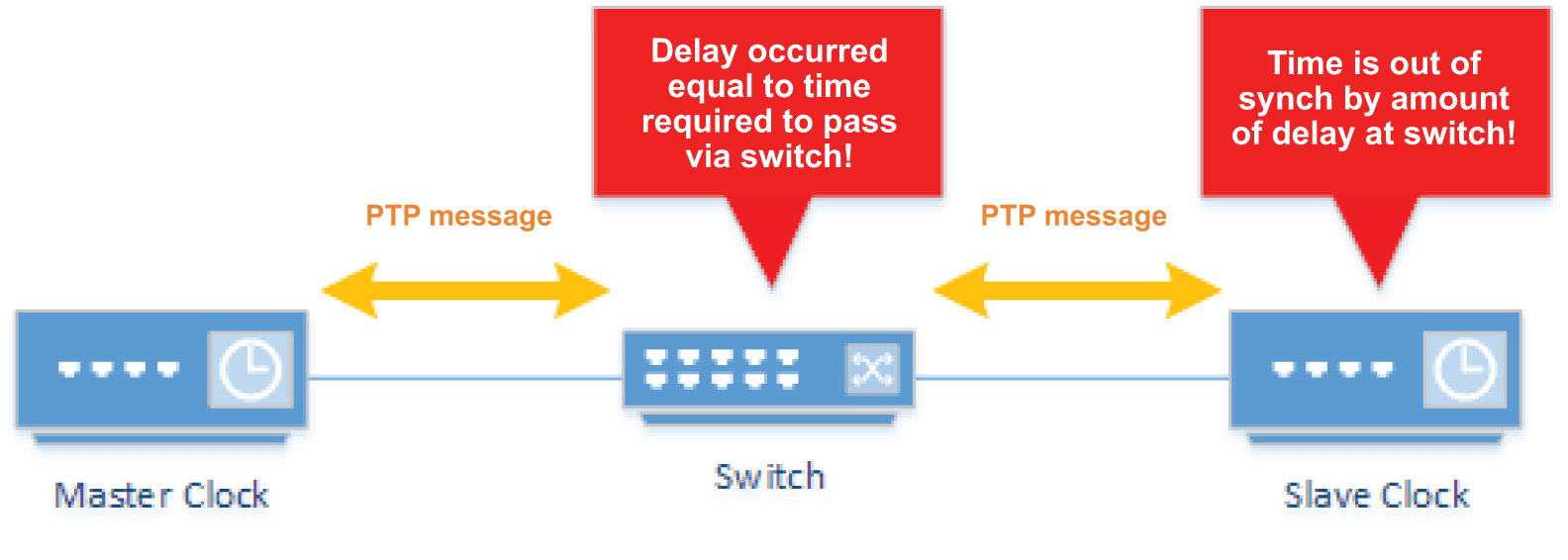
By using a PTP-compatible switch, a switch delay time is added to PTP messages forwarded by the switch, so that devices receiving the messages can correct its clock by including the switch delay time.
Forwarding via PTP-Compatible Switch
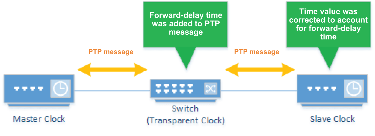
This product supports PTPv2 (IEEE1588-2008). Furthermore, it only supports the following operating mode.
Operating Mode
| Clock Type | Forward-Delay Measurement Mechanism | Method for Indicating Clock Time Information |
|---|---|---|
| Transparent clock (TC) | End-to-end (E2E) | 1-step |
2 Definition of Terms Used
- Master Clock
PTP-compatible device that distributes reference clock times used to synchronize other PTP-compatible devices on the communication route.
- Slave Clock
PTP-compatible devices synchronized based on the clock times sent out by the master clock.
- Transparent Clock
Device that measures the time required for PTP messages to pass through devices and forwards that information in PTP messages.
- End-to-End Mechanism
System for measuring the forward-delay time between master and slave clocks. Switches and other forwarding devices only attach corrected forward-delay time values to PTP messages.
- 1-step
Method of notifying time information with one PTP message.
3 Function Details
This product supports the following functionality.
- Operating mode setting
- PTP message forwarding protocol setting
3.1 Operating Mode Setting
Currently, only the end-to-end transparent clock (1-step) operating mode is supported and cannot be changed.
In the future, if functionality is extended, the ptp mode command will be used to set the operating mode.
3.2 PTP Message Forwarding Protocol Setting
PTP messages can be forwarded using a variety of frame formats.
To forward PTP messages via a switch, it must use the same frame format as the master and slave clocks.
This product supports both IPv4 UDP and IPv6 UDP.
The forwarding protocol is set using the ptp tranport protocol command.
4 Related Commands
Related commands are indicated below.
For details on the commands, refer to the Command Reference.
List of related commands
| Operations | Operating Commands |
|---|---|
| System PTP setting | ptp |
| Interface PTP setting | ptp |
| Operating mode setting | ptp mode |
| PTP message forwarding protocol setting | ptp transport protocol |
| Show PTP settings status | show ptp |
| Show interface PTP information | show ptp interface |
5 Examples of Command Execution
5.1 End-to-End Transparent Clock Settings
The following describes using IPv4 UDP as the protocol for forwarding PTP messages.
It enables the PTP function for the interface connected to the master and slave clocks.
The PTP function is left disabled for interfaces connected to non-PTP compatible devices.
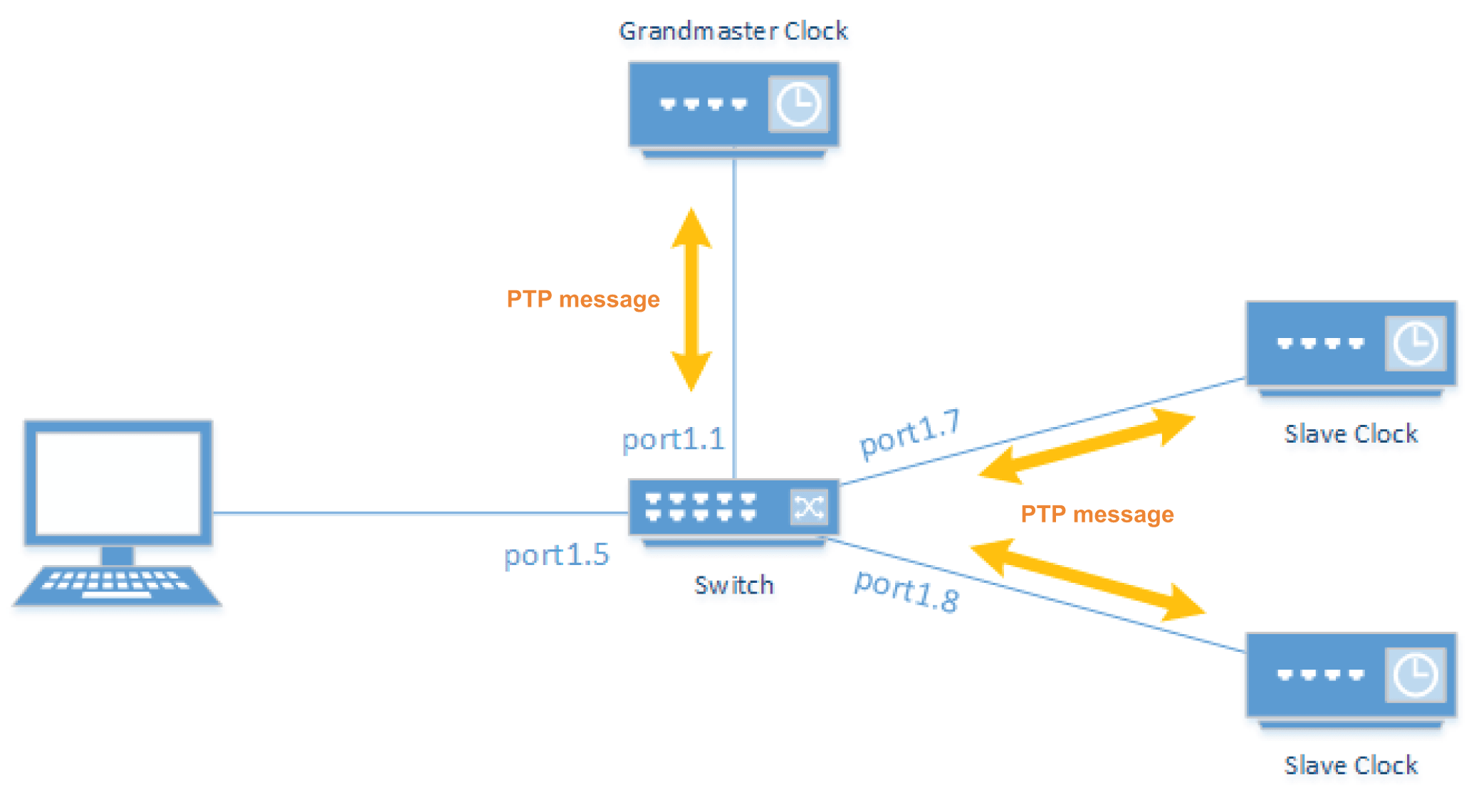
- Enable the PTP function for the system.
Yamaha(config)#ptp enable
- Set IPv4 UDP as the protocol for forwarding PTP messages.
Yamaha(config)#ptp transport protocol udp ipv4
- Enable the PTP function for the interface.
Yamaha(config)#interface port1.1
Yamaha(config-if)#ptp enable       ...(Enable PTP function at port1.1)
Yamaha(config-if)#exit
Yamaha(config)#interface port1.7
Yamaha(config-if)#ptp enable       ...(Enable PTP function at port1.7)
Yamaha(config-if)#exit
Yamaha(config)#interface port1.8
Yamaha(config-if)#ptp enable       ...(Enable PTP function at port1.8)
Yamaha(config-if)#exit
- Confirm the PTP settings.
Yamaha#show ptp
  PTP State                 : Enabled
  PTP Mode                  : Transparent Clock
  Delay Mechanism           : End to End
  Step Mode                 : One-step
  Transport Protocol        : UDP (IPv4)
- Confirm the interface PTP setting.
Yamaha#show ptp interface
Interface  PTP
-------------------
port1.1    Enable
port1.2    Disable
port1.3    Disable
port1.4    Disable
port1.5    Disable
port1.6    Disable
port1.7    Enable
port1.8    Enable
6 Points of Caution
- This function only supports 1 Gbps or 10 Gbps communication speeds.
- This function cannot be used in combination with the stack function.
- PTP messages are always flooded, even if IGMP/MLD snooping is enabled.
7 Related Documentation
- PTP
- IEEE1588-2008
Buzzer
1 Function Overview
This product emits an internal buzzer sound to audibly notify the user whenever the product is started up, an SD card is inserted, or a loop error or other error occurs.
The buzzer is disabled in default settings, but can be enabled as necessary, as described in the next chapter.
The types of buzzer sounds and conditions for emitting the sounds are indicated below.
| Buzzer types | Conditions (events) for sounding the buzzer |
|---|---|
| System error sound | Temperature error detected |
| Fan error detected | |
| Port error sound | Error detected due to a loop shutting down or blocking a port |
| Optical input level error detected at an SFP port | |
| Startup sound | Product startup finished |
| SD card mounting sound | SD card was mounted |
| SD card unmounting sound | SD card was unmounted |
| Mute activation sound | Mute was activated |
| Mute deactivation sound | Mute was deactivated |
| “Find this switch” function execution sound | The “find this switch” function was executed |
The actual sound emitted can be checked using the beep buzzer command.
Triggers/criteria for emitting buzzer sounds can be selected using the buzzer trigger command.
2 Definition of Terms Used
System error
A general term for any error that affects actions of the overall switch. They are caused by temperature or fan errors.
Port error
A general term for any error related to a switch port. They are caused by loop detection shutting down or blocking a port or by an optical input level error at an SFP port.
3 Function Details
3.1 Buzzer settings and mute function
System settings, trigger settings, and the mute status must be managed appropriately for the product to emit user-specified buzzer sounds.
Those settings are described below.
- System settings
- The buzzer can be enabled/disabled for the entire system.
- Use the buzzer enable/disable command to specify that setting.
- The setting is disabled in default settings.
- Trigger setting
- Individual buzzer trigger settings can be specified and buzzer sounds can be emitted for user-specified triggers.
- Use the buzzer trigger command to specify that setting.
- All buzzer sounds are disabled in default settings.
- Triggers are described below.
Trigger types Conditions (events) for sounding the buzzer temperature Temperature error detected fan Fan error detected loop Error occurred due to loop detection shutting down or blocking a port sfp Optical input level error occurred at an SFP port startup Product startup finished sd SD card was mounted SD card was unmounted All (collectively enable all triggers indicated above) -
- Mute function
- Used to temporarily mute sound.
- Buzzer sounds can be muted using the mute buzzer command.
- Buzzer sounds are unmuted based on the following criteria without saving the setting in the config settings.
- When the unmute buzzer command is executed.
- When the buzzer disable command is executed.
- When the device is restarted.
- When the main switch and stack are configured with the mute function disabled.
3.2 The “find this switch” function
This function uses buzzers and LEDs to search for switches.
It is useful for identifying this switch in a server room or other location with many devices installed.
The function can be started with the find switch start and stopped with the find switch stop command.
The following parameter settings can be selected for the find switch start command.
| Parameters | Description |
|---|---|
| buzzer | Emits a buzzer sound for executing the “find this switch” function. |
| led | Flashes an orange port LED. |
3.3 Priority order of buzzer sounds
If multiple events occur simultaneously, sounds are emitted according to a priority order.
For example, if an SD card is inserted during a system error, the system error sound is paused to emit an SD card mounting sound.
The sound priority order is indicated below.
| Priority order | Buzzer sound type |
|---|---|
| High | Startup sound |
| Mute deactivation sound | |
| Mute activation sound | |
| SD card mounting sound | |
| SD card unmounting sound | |
| “Find this switch” function execution sound | |
| System error sound | |
| Low | Port error sound |
3.4 Characteristics of each buzzer sound
3.4.1 System error sound
System error sounds will continue sounding as long as a system error remains active.
Criteria for emitting a system error sound
| System error types | Description |
|---|---|
| Temperature error | Internal temperature exceeded a specific threshold value |
| Fan error | The fan stopped. |
The system error sound is stopped when the temperature error is resolved.
3.4.2 Port error sound
Port error sounds will continue sounding as long as a port error remains active.
Criteria for emitting a port error sound
| Error type | Description |
|---|---|
| Loop | A port was blocked because a loop was detected |
| A port was shut down because a loop was detected | |
| SFP optical input level | SFP optical input level fell below the normal range |
| SFP optical input level exceeded the normal range |
The cause of port errors can be checked using the show error port-led command.
3.4.3 Startup sound
The startup sound is emitted only once when the product is finished starting up.
3.4.4 SD mounting/unmounting sound
The SD mounting/unmounting sound is emitted only once when an SD card is mounted or unmounted.
3.4.5 Mute activation/deactivation sound
The mute activation/deactivation sound is emitted only once when the mute function is activated or deactivated.
3.4.6 “Find this switch” function execution sound
When the find switch start command is executed, the “find this switch” function execution sound is repeatedly emitted for the specified number of seconds.
4 Related Commands
Related commands are indicated below.
For details on the commands, refer to the Command Reference.
List of related commands
| Operations | Operating commands |
|---|---|
| Enable the buzzer system | buzzer |
| Set a buzzer trigger | buzzer trigger |
| Enable/disable the mute function | mute buzzer |
| unmute buzzer | |
| Check the buzzer sound | beep buzzer |
| Show buzzer sound information | show buzzer |
| Start/stop the “find this switch” function | find switch start |
| find switch stop |
5 Examples of Command Execution
5.1 Sending a buzzer notification if a port is shut down because a loop was detected
- Enable the buzzer for the entire system.
Yamaha(config)#buzzer enable
- Enables the setting for emitting a buzzer sound if an error occurred due to a loop detection shutting down or blocking a port.
Yamaha(config)#buzzer trigger loop
- Checks actual port error sound emitted.
Yamaha#beep buzzer port-error
- Indicates the buzzer status.
An example assuming an error occurred is shown below.
Yamaha#show buzzer
System          : Enable
Mute            : Disable
Status          : Beeping (Loop)
Enabled trigger : Loop
- The sound is muted to temporarily silence the sound.
Yamaha#mute buzzer
5.2 Executing the “find this switch” function
- Enable the buzzer for the entire system.
Yamaha(config)#buzzer enable
- This searches for the switch based on sound and LED indicators for thirty minutes.
Yamaha#find switch start 30 buzzer led
- The “find this switch” function can also be canceled.
Yamaha#find switch stop
6 Points of Caution
6.1 Activating the “find this switch” function
The buzzer will not sound if the buzzer system setting is disabled or the mute function is activated.
If the current LED mode is OFF, the LED will not flash.
6.2 Buzzer operations during firmware updates
Buzzer operations are disabled while the product firmware is being updated.
6.3 Buzzer operations when a stack is configured
If a stack is configured, the buzzer sound is emitted from the member switch where the event occurred.
For example, if the fan stopped in one of the member switches, that switch will emit a system error sound.
The following indicates whether or not each command is enabled for the entire stack or only the member switch.
| Commands | Enabled member switches |
|---|---|
| beep buzzer | Enabled in switch where the command was executed |
| find switch start/stop | |
| show buzzer | |
| mute/unmute buzzer | Enabled in entire stack |
| buzzer enable/disable | |
| buzzer trigger |
- Behavior in a stack configuration is as follows.
- Connecting a member switch with the mute function enabled to a member switch with the mute function disabled
- The status is determined by the mute function status of the main switch.
- Connecting a member switch with the mute function enabled to a member switch with the mute function disabled
7 Related Documentation
None
- SWX3220 Series Technical Data (Basic Functions)
- Maintenance and operation functions
- List of default settings
List of default settings
SWX3220 series default settings are indicated below.
System-wide default settings
| Category | Setting Parameter | Setting Value |
|---|---|---|
| Console | Console timeout | 600 sec |
| Number of VTYs | 8 | |
| Number of lines displayed | 24 | |
| User accounts | Default administrative users | User name: admin Password: admin |
| Administrative password | admin | |
| Password encryption | Not encrypted | |
| Time management | Time zone | JST (UTC + 9.0) |
| NTP server | None | |
| NTP update cycle | Once per hour | |
| SNMP | Operation | Disabled |
| RMON | Operation | Enabled |
| SYSLOG | Debug level log output | OFF |
| Information level log output | ON | |
| Error level log output | ON | |
| SYSLOG server | None | |
| Firmware Updating | Download URL | http://www.rtpro.yamaha.co.jp/firmware/revision-up/swx3220.bin |
| Allow downward revision | Not allowed | |
| Timeout | 300 sec | |
| LLDP | Operation | Enabled |
| Automatic setting function | Enabled | |
| L2MS | Operation | Enabled |
| Role | Agent | |
| Stacking | Operation | Disabled |
| Stack ID | 1 | |
| IP address range used for stack port | 192.168.250.0/24 | |
| Access Control | Telnet server status | Start |
| Telnet server access | Allow only VLAN #1 | |
| SSH server status | Do not start | |
| TFTP server status | Do not start | |
| HTTP server status | Start | |
| HTTP server access | Allow only VLAN #1 | |
| Secure HTTP server status | Do not start | |
| Management VLAN | VLAN interface | VLAN #1 |
| Interface Control | Link aggregation | None |
| Port authentication | Disabled | |
| Port security | Disabled | |
| PoE power supply | - | |
| Layer 2 Functions | Automatic MAC address acquisition | Enabled |
| Automatic MAC address acquisition aging time | 300 sec | |
| Spanning tree | Enabled | |
| Proprietary loop detection | Disabled | |
| Multiple VLAN | None | |
| Layer 3 Functions | Static routing | None |
| Routing between VLANs | Disabled | |
| Policy-based routing | None | |
| OSPF | Disabled | |
| RIP | Disabled | |
| VRRP | Disabled | |
| IP Multicasting | IGMP snooping | Enabled |
| MLD snooping | Enabled | |
| IGMP | Disabled | |
| PIM | Disabled | |
| DNS client | Operation | Enabled |
| Traffic Control | QoS | Disabled |
| QoS (DSCP - Transmission queue ID conversion table) | None | |
| Flow control (IEEE 802.3x) | Disabled | |
| ACL | None | |
| AP layer functionality | DHCP server | Disabled |
| DHCP relay | Disabled | |
| DNS relay | Disabled | |
| RADIUS server | Disabled | |
| WebGUI | Language setting | Japanese |
Default settings for each LAN/SFP port
| Category | Setting Parameter | Setting Value |
|---|---|---|
| Basic Settings | Speed/communication mode setting | auto |
| Cross/straight automatic detection | Enabled | |
| MRU | 1,522 Byte | |
| Port description | None | |
| EEE | Disabled | |
| Port Mode | Access | |
| Associated VLAN ID | 1 (default VLAN) | |
| L2MS | L2MS filter | Disabled |
| L2 Switching | Spanning tree | Enabled |
| Proprietary loop detection | Enabled | |
| Traffic Control | QoS trust mode | CoS |
| Flow control (IEEE 802.3x) | Disabled | |
| Storm control | Disabled | |
| LLDP Agent | Transmit/receive mode | Transmit and receive |
| PoE Power Supply | Power supply actions | - |
| Power supply priority order | - |
Settings for default VLAN (vlan1)
| Setting Parameter | Setting Value | |
|---|---|---|
| IPv4 Address | 192.168.100.240/24 | |
| IGMP Snooping | Operation | Enabled |
| Querier | Disabled | |
| Fast-Leave | Disabled | |
| Check TTL | Enabled | |
- SWX3220 Series Technical Data (Basic Functions)
- Interface control functions
Interface control functions
- SWX3220 Series Technical Data (Basic Functions)
- Interface control functions
- Interface basic functions
Interface basic functions
1 Function Overview
Here we explain the basic interface functions of this product.
2 Definition of Terms Used
None
3 Function Details
3.1 Interface types
This product can handle the five interface types shown in the table below.
Interface list
| Interface types | Interface ID | Explanation |
|---|---|---|
| LAN port | port | A physical port of this product. There are two types: a fixed LAN port and a removable SFP+ port. This interface is expressed as port followed by “stack ID” + “.” + “port number printed on the chassis.” Specifying LAN port #1: port1.1 |
| SFP+ port | ||
| VLAN interface | vlan | A user-defined VLAN. This interface is expressed as vlan followed by “VLAN ID.” Specifying VLAN1: vlan1 |
| Static logical interface | sa | This is the user-defined link aggregation. Multiple LAN/SFP ports can be grouped together and used as one interface. This interface is expressed as “sa” or “po,” followed by “logical link ID.” Specifying the LACP logical interface for logical link ID #1: po1 |
| LACP logical interface | po |
3.2 Interface control
The interface on this product can be controlled as shown in the table below.
Interface control items
| Control items | Commands | Explanation |
|---|---|---|
| Set description | description | Sets the description text for the applicable interface. |
| Enable/disable | shutdown | Enables/disables the interface. |
| Communication speed/communication mode | speed-duplex | Sets the communication speed and communication mode for the interface. (Select from the following values.)
|
| Auto-negotiation type | negotiation | Sets the communication types supported by interface auto-negotiation. (Multiple types can be selected from the following.)
|
| MRU | mru | Sets the maximum frame size that can be received by the interface, within a range of 64–10,240 bytes. |
| Cross/straight automatic detection (Auto MDI/MDI-X function) | mdix | This function automatically detects the connection port type (MDI or MDI-X), allowing for interconnection without relying on the cable type (cross or straight). |
| Speed downshift | - | This function automatically drops communication speed for trying links. This function is always enabled for LAN ports. (Cannot be disabled.) |
| EEE | eee | Specifies whether EEE (Energy-Efficient Ethernet) is used. This is standard for IEEE 802.3az. |
Command control of the interface is performed as shown on the table below.
Interface control functionality chart
| Interface name | Set description | Enable/disable | Communication speed/communication mode | Auto-negotiation type | MRU | Cross/straight automatic detection | EEE |
|---|---|---|---|---|---|---|---|
| LAN port | ✓ | ✓ | ✓ | ✓ | ✓ | ✓ | ✓ |
| SFP+ port | ✓ | ✓ | ✓ | - | ✓ | - | - |
| VLAN interface | ✓ | - | - | - | - | - | - |
| Static logical interface | ✓ | ✓ | - | - | - | - | - |
| LACP logical interface | ✓ | ✓ | - | - | - | - | - |
Communication speed/communication mode chart
| Communication speed/communication mode | LAN port | SFP+ port |
|---|---|---|
| Auto negotiation | Yes | Yes |
| 10 Gbps / full duplex | No | Yes*1 |
| 5 Gbps / full duplex | No | - |
| 2.5 Gbps / full duplex | No | - |
| 1 Gbps / full duplex | No | - |
| 100 Mbps / full duplex | Yes | - |
| 100 Mbps / half duplex | Yes | - |
*1 If an SFP module is connected to an SFP+ port, it will function at 1 Gbps / full-duplex.
3.3 LAN/SFP port defaults
Initially, this product’s LAN/SFP ports will be in the following state.
- All LAN/SFP ports function as access ports (ports that handle untagged frames), and belong to the default VLAN (VLAN #1).
- The following functions are enabled for the default VLAN (VLAN #1) to which all LAN/SFP ports belong.
- MSTP: Multiple Spanning Tree Protocol
- IGMP Snooping
- IPv4 address (192.168.100.240/24)
- Access from a Telnet client
- Access from a web client
3.4 Port mirroring
This product provides a port mirroring function, which copies the data traffic from a selected LAN/SFP port to another specified port.
The communication status can be analyzed by collecting the copied packets.
The product enables specifying up to one sniffer port.
The monitoring direction (send/receive, send only, or receive only) can be selected for monitored ports.
The mirror command can be used to set the port mirroring.
The port mirroring setting is disabled in default settings.
3.5 Frame counter
This product counts the number of frames transmitted/received for each LAN/SFP port. (This is called a “frame counter”.)
To reference the frame counter, use the show frame counter command.
The table below shows the display items for the frame counter and their maximum values.
Received frame counter display items
| Display item | Explanation | Maximum value |
|---|---|---|
| Octets | Number of octets received | 18,446,744,073,709,551,615 |
| Packets (*1) | Number of packets received | 34,359,738,360 |
| Broadcast packets (*2) | Number of broadcast packets received | 4,294,967,295 |
| Multicast packets (*2) | Number of multicast packets received | 4,294,967,295 |
| Unicast packets (*2) | Number of unicast packets received | 4,294,967,295 |
| Undersize packets (*2) | Number of undersize packets received (packets smaller than 64 octets) | 4,294,967,295 |
| Oversize packets (*2) | Number of oversize packets received (packets larger than 1,523 octets (*3)) | 4,294,967,295 |
| Fragments (*2) | Number of fragment packets received (packets smaller than 64 octets whose CRC is incorrect) | 4,294,967,295 |
| Jabbers (*2) | Number of jabber packets received (packets larger than 1,523 octets whose CRC is incorrect (*3)) | 4,294,967,295 |
| FCS errors (*2) | Number of FCS error packets received | 4,294,967,295 |
| RX errors | Number of reception errors | 4,294,967,295 |
| Drop packets (*4) | Number of packets dropped from the reception buffer | 4,294,967,295 |
(*1): Packets is the total value of the (*2) packets.
(*3): This will change, depending on the MRU that is set for the LAN/SFP port.
(4): This is shown only if tail drop is disabled.
Transmitted frame counter display items
| Display item | Explanation | Maximum value |
|---|---|---|
| Octets | Number of octets transmitted | 18,446,744,073,709,551,615 |
| Packets (*1) | Number of packets transmitted | 12,884,901,885 |
| Broadcast packets (*2) | Number of broadcast packets transmitted | 4,294,967,295 |
| Multicast packets (*2) | Number of multicast packets transmitted | 4,294,967,295 |
| Unicast packets (*2) | Number of unicast packets received | 4,294,967,295 |
| TX errors | Number of transmission errors | 4,294,967,295 |
| Collisions | Number of collision occurrences | 4,294,967,295 |
| Drop Packets(*3) | Number of tail-dropped transmission packets | 536,870,911 |
(*1): The packet value is the total of the (*2) packets.
(3): This is shown only if tail drop is enabled.
Transmitted/received frame counter display items
| Display item | Explanation | Maximum value |
|---|---|---|
| 64 octet packets | Number of packets with 64 octet length transmitted/received | 4,294,967,295 |
| 65–127 octet packets | Number of packets with 65–127 octet length transmitted/received | 4,294,967,295 |
| 128–255 octet packets | Number of packets with 128–255 octet length transmitted/received | 4,294,967,295 |
| 256–511 octet packets | Number of packets with 256–511 octet length transmitted/received | 4,294,967,295 |
| 512–1,023 octet packets | Number of packets with 512–1,023 octet length transmitted/received | 4,294,967,295 |
| 1,024–MAX octet packets | Number of packets with 1,024–maximum octet length (*1) transmitted/received | 4,294,967,295 |
(*1): This will change, depending on the MRU that is set for the LAN/SFP port.
The frame counter can also be cleared by using the clear counters command.
When you execute the show interface command which shows the status of the LAN/SFP ports, information on the number of transmitted and received frames is shown, but this information is shown based on the frame counter information.
The number of frames transmitted/received that is displayed using the show interface command and how the frame counter is handled are shown below.
- Number of frames transmitted/received that is displayed by the show interface command, and how the frame counter is handled
Display item Information on the frame counter referred to input packets Received frame counter packets bytes Received frame counter octets multicast packets Received frame counter multicast packets drop packets(*1) Received frame counter drop packets output packets Transmitted frame counter packets bytes Transmitted frame counter octets multicast packets Transmitted frame counter multicast packets broadcast packets Transmitted frame counter broadcast packets drop packets(*1) Transmitted frame counter drop packets (*1) If tail drop is enabled this shows only the transmission information; if it is disabled this shows only the reception information.
3.6 SFP module optical receive level monitoring
This product provides functionality for monitoring the optical receive level of an SFP/SFP+ module connected to the SFP/SFP+ port.
If a fault occurs in an SFP/SFP+ module’s optical receive level, this product’s port lamp indications change to a dedicated state, and a SYSLOG message is output.
When the optical receive level returns to the normal range, this product’s port lamp indications will recover, and a SYSLOG message is output.
The SYSLOG message is not output when the corresponding port is linked down.
The SFP/SFP+ module’s optical receive level monitoring settings can be made using the sfp-monitor command.
By default, SFP module optical receive level monitoring is enabled.
3.7 Transmit queue usage monitoring
If the transmit queue’s usage ratio becomes high (above 60%, above 100%), a SYSLOG message is output.
A SYSLOG message is also output when the transmit queue’s usage ratio returns to the normal range (below 50%).
The transmission queue usage monitoring setting (for the overall system or individual LAN/SFP ports) can be set using the tx-queue-monitor command.
All transmission queue usage monitoring settings are enabled in default settings.
4 Related Commands
The related commands are shown below.
For details on the commands, refer to the Command Reference.
Basic interface functions: list of related commands
| Operations | Operating Commands |
|---|---|
| Set description | description |
| Shutdown | shutdown |
| Set communication speed and communication mode | speed-duplex |
| Sets the auto-negotiation type | negotiation |
| Set MRU | mru |
| Set cross/straight automatic detection | mdix auto |
| Set EEE | eee |
| Show EEE capabilities | show eee capabilities |
| Show EEE status | show eee status |
| Set port mirroring | mirror |
| Show port-mirroring status | show mirror |
| Show interface status | show interface |
| Show simplified interface status | show interface brief |
| Shows auto-negotiation information | show interface negotiation |
| Show frame counter | show frame-counter |
| Clear frame counters | clear counters |
| Show SFP/SFP+ status | show ddm status |
| Set SFP module optical receive level monitoring | sfp-monitor rx-power |
| Set transmission queue usage monitoring setting (system) | tx-queue-monitor usage-rate |
| Set transmission queue usage monitoring setting (LAN/SFP ports) | tx-queue-monitor usage-rate |
| Show the transmission queue usage monitoring setting | show tx-queue-monitor |
| Resets interface | interface reset |
5 Examples of Command Execution
5.1 Basic LAN port settings
Some examples of basic LAN port settings are shown below.
For details on how to make the settings, refer to the Command Reference.
- Set the description text for LAN port #1 (port1.1).
Yamaha(config)#interface port1.1
Yamaha(config-if)#description Connected to rtx1200-router
- Disable LAN port #1 (port1.1).
Yamaha(config)#interface port1.1
Yamaha(config-if)#shutdown
- Enable LAN port #1 (port1.1).
Yamaha(config)#interface port1.1
Yamaha(config-if)#no shutdown
- Set the communication speed and communication mode for LAN port #1 (port1.1) to 100Mbps/Full.
Yamaha(config)#interface port1.1
Yamaha(config-if)#speed-duplex 100-full
5.2 Setting port mirroring
In this example, we will set LAN port #1 to monitor the frames transmitted/received by LAN port #4 and the frames transmitted by LAN port #5.
The roles of the ports are shown below.
- Sniffer port: LAN port #1 (port 1.1)
- Monitored ports: LAN port #4 (port 1.4) and LAN port #5 (port 1.5)
- Specifies the port monitored for LAN port #1 (port 1.1), which is a sniffer port.
Yamaha(config)#interface port1.1
Yamaha(config-if)#mirror interface port1.4 direction both     ... (Monitor transmission/reception frames)
Yamaha(config-if)#mirror interface port1.5 direction transmit ... (Monitor transmission frames)
- Checks the port mirroring setting.
Yamaha#show mirror
Sniffer Port   Monitored Port  Direction
=============  ==============  ==========
port1.1        port1.4         both
port1.1        port1.5         transmit
5.3 Show LAN/SFP port information
- Confirm the status of LAN port #1 (port1.1).
Yamaha#show interface port 1.1
Interface port1.1
  Link is UP
  Hardware is Ethernet
  HW addr: 00a0.deae.b89f
  Description: Connected to router
  ifIndex 5001, MRU 1522
  Speed-Duplex: auto(configured), 1000-full(current)
  Auto MDI/MDIX: on
  Vlan info :
    Switchport mode        : access
    Ingress filter         : enable
    Acceptable frame types : all
    Default Vlan           :    1
    Configured Vlans       :    1
  Interface counter:
    input  packets          : 0
           bytes            : 0
           multicast packets: 0
    output packets          : 0
           bytes            : 0
           multicast packets: 0
           broadcast packets: 0
           drop packets     : 0
6 Points of Caution
None
7 Related Documentation
None
Link aggregation
1 Function Overview
Link aggregation is a function used to combine multiple LAN/SFP ports that connect network devices, and handle them as a single logical interface.
Link aggregation is a technology that is useful when multiple communications occur. Communications can be distributed by using a load balance function within the combined lines.
If one LAN/SFP port fails within the lines that were combined using link aggregation, and communications cannot be made, the other ports will continue communicating.
Link aggregation function overview
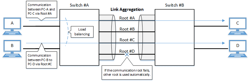
The link aggregation functions in this switch are shown below.
Link aggregation functions
| Functions provided | Contents |
|---|---|
| Static link aggregation | Link aggregation for manually setting the LAN/SFP ports to combine. This begins to operate as a logical interface when the LAN/SFP ports link up. |
| LACP link aggregation | Link aggregation that uses LACP to combine the LAN/SFP ports. This begins to operate as a logical interface when the negotiation via LACP between the connected devices is successful. |
2 Definition of Terms Used
- LACP
Abbreviation for “Link Aggregation Control Protocol”. This is a technology standardized in IEEE802.1AX-2008, and is also called EtherChannel.
- Load balance
This is a function to distribute forwarded frames between the LAN/SFP ports that are associated with the logical interface.
As a distribution rule, the L2/L3/L4 information within frames is used.
3 Function Details
3.1 Static/LACP link aggregation: common specifications
The common specifications for the static/LACP link aggregation functions of this switch are shown below.
- The link aggregation on this switch can be defined for 127 interfaces, including both static and LACP (126 interfaces for stacks).
A single logical interface can be associated with up to eight LAN/SFP ports.
- The settings shown below must be the same for each of the LAN/SFP ports contained within.
- Port mode (access/trunk [including native VLAN settings])
- Associated VLAN
- QoS trust mode (including port priority and default CoS settings)
- Executes the following process when a LAN/SFP port is associated with a logical interface.
- LAN/SFP ports that are linked up will be linked down.
The logical interface’s default value will be set to shutdown, in order to safely integrate the logical interface into the system.
- MSTP settings will be discarded and will revert to their defaults.
When dissociating a LAN/SFP port from the logical link, the MSTP settings for the relevant port will revert to their defaults as well.
- LAN/SFP ports that are linked up will be linked down.
- The following operations can be performed for the logical interface.
- Add description text (description command)
- Enable/disable the interface (shutdown command)
- Another LAN/SFP port cannot be associated with a logical interface in operation.
To associate a LAN/SFP port, make sure to shut down the logical interface before associating.
- LAN/SFP ports that are associated with a logical interface that is in operation cannot be removed.
When dissociating a LAN/SFP port, make sure to shut down the logical interface before dissociating.
LAN/SFP ports that have been dissociated from a logical interface will be in shutdown mode. Enable the ports as necessary (using “no shutdown”).
- Load balance settings can be made on the logical interface. The rules that can be set for this are shown below.
The default value when defining a logical interface is the destination/source MAC address.
- Destination MAC address
- Source MAC address
- Destination/source MAC address
- Destination IP address
- Source IP address
- Destination/source IP address
- Destination port number
- Source port number
- Destination/source port number
3.2 Static link aggregation
The operating specifications for static link aggregation are shown below.
- An interface number from 1–96 can be assigned to the static logical interface.
- Use the static-channel-group command to associate a LAN/SFP port with a static logical link interface.
- When associating a LAN/SFP port with an interface number for which there is no static logical interface, a new logical interface will be generated.
- When the associated port no longer exists as a result of removing a LAN/SFP port from a static logical interface, the relevant logical interface will be deleted.
- Use the show static-channel-group command to show the static logical link interface’s status.
3.3 LACP link aggregation
The operating specifications for LACP link aggregation are shown below.
Refer to “3.1 Static/LACP link aggregation: common specifications” for the common specifications of static link aggregation.
- An interface number from 1–127 can be assigned to the LACP logical interface.
- Use the channel-group command to associate a LAN/SFP port with an LACP logical link interface.
- When associating an LAN/SFP, specify the following operating modes. (It is recommended to specify “active mode”.)
- Active mode
The LACP frame will be voluntarily transmitted, and negotiation with the opposing device’s port will begin.
- Passive mode
The LACP frame will not be voluntarily transmitted, but will instead be transmitted when a frame is received from the opposing device.
- Active mode
- When associating a LAN/SFP port with an interface number for which there is no LACP logical interface, a new logical interface will be generated.
- When the associated port no longer exists as a result of removing a LAN/SFP port from an LACP logical interface, the relevant logical interface will be deleted.
- When associating an LAN/SFP, specify the following operating modes. (It is recommended to specify “active mode”.)
- The parameters that influence the operations of the LACP logical interface are shown below.
- LACP timeout
LACP timeout indicates the down time that was determined, when an LACP frame has not been received from the opposing device.
Specify either “Long” (90 sec.) or “Short” (3 sec.) using the lacp timeout command.
The LACP timeout value is stored in the LACP frame and transmitted to the opposing device.
The opposing device that received the frame will transmit the LACP frames it has stored at intervals equaling 1/3 of the LACP timeout value.
The default value when the logical interface is generated is “Long (90 sec.)”.
- LACP system priority
The LACP system priority is used when deciding which device will control the logical interface, when communicating with the opposing device. The LACP system priority and MAC address values (in combination referred to as the system ID) are exchanged with the interfacing device and the device with the highest LACP system priority level is assigned control. If both devices have the same LACP system priority level, the device with the lower MAC address is assigned control.
The device assigned control determines which LAN or SFP ports associated with the logical interface are enabled (activated).
LACP system priority values within the range 1 to 65535 can be specified using the lacp system-priority command, where the lower the setting value, the higher the priority level. The default value when the logical interface is generated is set to 32768 (0x8000).
- LACP port priority
LACP port priority is used to control active/standby for the LAN/SFP ports that are associated with the logical interface. If more than the maximum number of LAN/SFP ports (8 ports) is associated with a logical interface, then the port status is controlled based on the LACP port priority.
If ports have the same LACP port priority, then the port with the lower port number is given priority. If a stack is configured, port numbers for switches with a lower stack ID are prioritized regardless of the port number. For example, port 1.10 is prioritized over port 2.1.
LACP system priority values within the range 1 to 65535 can be specified using the lacp port-priority command, where the lower the setting value, the higher the priority level. The default LACP port priority setting is 32768 (0x8000).
- LACP timeout
- LAN/SFP ports in half-duplex communication mode do not support LACP link aggregation.
- Half-duplex LAN/SFP ports that are associated with an LACP logical interface are never activated.
- The following describes actions that occur if LAN/SFP ports with different communication speeds are located on the same logical interface.
To configure link aggregation with a mixture of different communication speeds, enable multi-speed link aggregation.
- Actions if multi-speed link aggregation is enabled (lacp multi-speed enable)
- Activate all associated ports (up to a maximum 8 ports), regardless of communication speed.
- Load balancing treats all associated ports as equivalent.
- That increases the risk of a communication overflow occurring at a slow affiliated port.
- If there are more than the maximum 8 LAN/SFP ports, higher priority values are assigned to faster affiliated ports.
- If the other device cannot accept a different communication speed, then both interacting devices mutually exchange lists of affiliated ports and activate affiliated port that can be used by both devices.
Consequently, the process is limited by the device that cannot accept different communication speeds.
- Actions if multi-speed link aggregation is disabled (lacp multi-speed disable)
- Only affiliated ports with a communication speed the same as the port first linked up are activated.
- Other ports with a different communication speed remain in standby mode.
- If auto negotiation is enabled, only affiliated ports with a communication speed that is the same as the negotiation result of the first negotiation will be activated.
- If links go down for all the ports first linked up, then the link will go down for the LACP logical interface as well.
- Only affiliated ports with a communication speed the same as the port first linked up are activated.
- Actions if multi-speed link aggregation is enabled (lacp multi-speed enable)
- The show etherchannel command can be used to check the LACP logical interface status.
- The show etherchannel status detail command can be used to check the activation status of affiliated ports.
- LACP link aggregation is used even if a stack is configured. However, the following restriction applies.
- A total of 126 logical interfaces can be defined for both stacks and LACP.
4 Related Commands
The related commands are shown below.
For details on the commands, refer to the Command Reference.
List of related commands
| Operations | Operating Commands |
|---|---|
| Set the static logical interface | static-channel-group |
| Show the static logical interface status | show static-channel-group |
| Set the LACP logical interface | channel-group |
| Set LACP system priority | lacp system-priority |
| Show LACP system priority | show lacp sys-id |
| LACP multi-speed link aggregation setting | lacp multi-speed |
| Set LACP timeout | lacp timeout |
| Clear LACP packet counter | clear lacp |
| Show LACP packet counter | show lacp counters |
| Show the status of the LACP logical interface | show etherchannel |
| Set load balance function rules | port-channel load-balance |
5 Examples of Command Execution
5.1 Setting the static logical interface
In this example, we will set link aggregation to use four LAN ports, in order to communicate between switches.
- Static logical interface setting example
- Static link aggregation is set to static.
The logical interface numbers are set to switch A: #2 and switch B: #5.
- The LAN ports associated with the logical interface are all access ports, and are associated with the VLAN #1000.
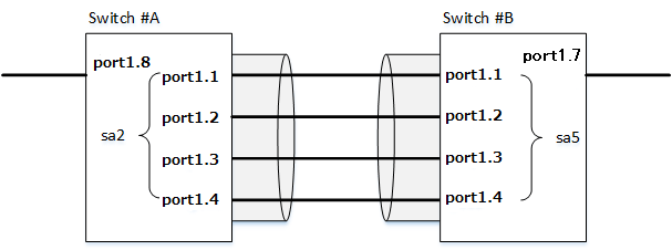
- Define [switch A] VLAN #1000, and associate it with LAN ports (#1, #2, #3, #4, #8).
Together with this, associate LAN ports (#1, #2, #3, #4) with the logical interface #2.
Yamaha(config)#vlan database ... (VLAN-ID #1000 definition)
Yamaha(config-vlan)#vlan 1000
Yamaha(config-vlan)#exit
Yamaha(config)#interface port1.8 ... (Set LAN port #8)
Yamaha(config-if)#switchport access vlan 1000 ... (Set as access port, and associate with VLAN #1000)
Yamaha(config-if)#interface port1.1 ... (Set LAN port #1)
Yamaha(config-if)#switchport access vlan 1000 ... (Set as access port, and associate with VLAN #1000)
Yamaha(config-if)#static-channel-group 2 ... (Associate with logical interface #2)
Yamaha(config-if)#interface port1.2
Yamaha(config-if)#switchport access vlan 1000
Yamaha(config-if)#static-channel-group 2
Yamaha(config-if)#interface port1.3
Yamaha(config-if)#switchport access vlan 1000
Yamaha(config-if)#static-channel-group 2
Yamaha(config-if)#interface port1.4
Yamaha(config-if)#switchport access vlan 1000
Yamaha(config-if)#static-channel-group 2
- Confirm the setting status of [switch A] logical interface #2.
Yamaha#show static-channel-group
% Static Aggregator: sa2
% Member:
   port1.1
   port1.2
   port1.3
   port1.4
- Define [switch B] VLAN #1000, and associate it with LAN ports (#1, #2, #3, #4, #7).
Together with this, associate LAN ports (#1, #2, #3, #4) with the logical interface #5.
Yamaha(config)#vlan database
Yamaha(config-vlan)#vlan 1000
Yamaha(config-vlan)#exit
Yamaha(config)#interface port1.7
Yamaha(config-if)#switchport access vlan 1000
Yamaha(config-if)#interface port1.1
Yamaha(config-if)#switchport access vlan 1000
Yamaha(config-if)#static-channel-group 5
Yamaha(config-if)#interface port1.2
Yamaha(config-if)#switchport access vlan 1000
Yamaha(config-if)#static-channel-group 5
Yamaha(config-if)#interface port1.3
Yamaha(config-if)#switchport access vlan 1000
Yamaha(config-if)#static-channel-group 5
Yamaha(config-if)#interface port1.4
Yamaha(config-if)#switchport access vlan 1000
Yamaha(config-if)#static-channel-group 5
- Confirm the setting status of [switch B] logical interface #5.
Yamaha#show static-channel-group
% Static Aggregator: sa5
% Member:
   port1.1
   port1.2
   port1.3
   port1.4
- Enable [switch A] logical interface.
Yamaha(config)#interface sa2 ... (Set logical interface #2)
Yamaha(config-if)#no shutdown ... (Enable logical interface)
- Enable [switch B] logical interface.
Yamaha(config)#interface sa5 ... (Set logical interface #5)
Yamaha(config-if)#no shutdown ... (Enable logical interface)
- Confirm the setting status of [switch A] logical interface.
Yamaha#show interface sa2 Interface sa2 Link is UP ... (is enabled) Hardware is AGGREGATE ifIndex 4502, MRU 1522 Vlan info : Switchport mode : access Ingress filter : enable Acceptable frame types : all Default Vlan : 1000 Configured Vlans : 1000 Interface counter: input packets : 1020 bytes : 102432 multicast packets: 1020 output packets : 15 bytes : 1845 multicast packets: 15 broadcast packets: 0 - Confirm the setting status of [switch B] logical interface.
Yamaha#show interface sa5
Interface sa5
  Link is UP
  Hardware is AGGREGATE
  ifIndex 4505, MRU 1522
  Vlan info :
    Switchport mode        : access
    Ingress filter         : enable
    Acceptable frame types : all
    Default Vlan           : 1000
    Configured Vlans       : 1000
  Interface counter:
    input  packets          : 24
           bytes            : 2952
           multicast packets: 24
    output packets          : 2109
           bytes            : 211698
           multicast packets: 2109
           broadcast packets: 0
5.2 Setting the LACP logical interface
In this example, we will set link aggregation to use four LAN ports, in order to communicate between switches.
- Set the LACP logical interface
- Use LACP for link aggregation.
The logical interface numbers are set to switch A: #10 and switch B: #20.
Set the switch A logical interface to active status, and the switch B logical interface to passive status.
- The LAN ports associated with the logical interface are all access ports, and are associated with the VLAN #1000.
- For load balance, set the destination/source IP address.

- Define [switch A] VLAN #1000, and associate it with LAN ports (#1, #2, #3, #4, #8).
Together with this, associate LAN ports (#1, #2, #3, #4) in active status with the logical interface #10.
The logical interface at this point in time will be in shutdown mode.
Yamaha(config)#vlan database
Yamaha(config-vlan)#vlan 1000 ... (VLAN #1000 definition)
Yamaha(config-vlan)#exit
Yamaha(config)#interface port1.8
Yamaha(config-if)#switchport access vlan 1000 ... (Set as access port, and associate with VLAN #1000)
Yamaha(config-if)#interface port1.1
Yamaha(config-if)#switchport access vlan 1000 ... (Set as access port, and associate with VLAN #1000)
Yamaha(config-if)#channel-group 10 mode active ... (Associate with logical interface #10 in an active status)
Yamaha(config-if)#interface port1.2
Yamaha(config-if)#switchport access vlan 1000
Yamaha(config-if)# channel-group 10 mode active
Yamaha(config-if)#interface port1.3
Yamaha(config-if)#switchport access vlan 1000
Yamaha(config-if)# channel-group 10 mode active
Yamaha(config-if)#interface port1.4
Yamaha(config-if)#switchport access vlan 1000
Yamaha(config-if)# channel-group 10 mode active
- Confirm the setting status of [switch A] logical interface #10.
Yamaha#show etherchannel % Lacp Aggregator: po10 % Member: port1.1 port1.2 port1.3 port1.4 Yamaha#show lacp sys-id ... (Check LACP system ID: set to the default value (0x8000)) % System 8000,00-a0-de-ae-b9-1f Yamaha#show interface po10 Interface po10 Link is DOWN ... (Link is down) Hardware is AGGREGATE ifIndex 4610, MRU 1522 Vlan info : Switchport mode : access Ingress filter : enable Acceptable frame types : all Default Vlan : 1000 Configured Vlans : 1000 Interface counter: input packets : 0 bytes : 0 multicast packets: 0 output packets : 0 bytes : 0 multicast packets: 0 broadcast packets: 0 - Define [switch B] VLAN #1000, and associate it with LAN ports (#1, #2, #3, #4, #7).
Together with this, associate LAN ports (#1, #2, #3, #4) in passive status with the logical interface #20.
The logical interface at this point in time will be in shutdown mode.
Yamaha(config)#vlan database
Yamaha(config-vlan)#vlan 1000 ... (VLAN #1000 definition)
Yamaha(config-vlan)#exit
Yamaha(config)#interface port1.7
Yamaha(config-if)#switchport access vlan 1000 ... (Set as access port, and associate with VLAN #1000)
Yamaha(config-if)#interface port1.1
Yamaha(config-if)#switchport access vlan 1000 ... (Set as access port, and associate with VLAN #1000)
Yamaha(config-if)#channel-group 20 mode passive ... (Associate with logical interface #20 in a passive status)
Yamaha(config-if)#interface port1.2
Yamaha(config-if)#switchport access vlan 1000
Yamaha(config-if)# channel-group 20 mode passive
Yamaha(config-if)#interface port1.3
Yamaha(config-if)#switchport access vlan 1000
Yamaha(config-if)# channel-group 20 mode passive
Yamaha(config-if)#interface port1.4
Yamaha(config-if)#switchport access vlan 1000
Yamaha(config-if)# channel-group 20 mode passive
- Confirm the setting status of [switch B] logical interface #20.
Yamaha#show etherchannel % Lacp Aggregator: po20 % Member: port1.1 port1.2 port1.3 port1.4 Yamaha#show lacp sys-id ... (Check LACP system ID: set to the default value (0x8000)) % System 8000,00-a0-de-ae-b8-7e Yamaha#show interface po20 Interface po20 Link is DOWN ... (Link is down) Hardware is AGGREGATE ifIndex 4620, MRU 1522 Vlan info : Switchport mode : access Ingress filter : enable Acceptable frame types : all Default Vlan : 1000 Configured Vlans : 1000 Interface counter: input packets : 0 bytes : 0 multicast packets: 0 output packets : 0 bytes : 0 multicast packets: 0 broadcast packets: 0 - Set the load balance of [switch A] to the destination/source IP address, and enable.
Yamaha(config)#port-channel load-labance src-dst-ip ... (Set load balancing)
Yamaha(config)#interface po10 ... (Set logical interface #10)
Yamaha(config-if)#no shutdown ... (Enable logical interface)
- Set the load balance of [switch B] to the destination/source IP address, and enable.
Yamaha(config)#port-channel load-labance src-dst-ip ... (Set load balancing)
Yamaha(config)#interface po20 ... (Set logical interface #20)
Yamaha(config-if)#no shutdown ... (Enable logical interface)
- Confirm the setting status of [switch A] logical interface.
Link up and confirm whether frames are being sent and received.
Yamaha#show interface po10 Interface po10 Link is UP Hardware is AGGREGATE ifIndex 4610, MRU 1522 Vlan info : Switchport mode : access Ingress filter : enable Acceptable frame types : all Default Vlan : 1000 Configured Vlans : 1000 Interface counter: input packets : 560 bytes : 58239 multicast packets: 560 output packets : 98 bytes : 12474 multicast packets: 98 broadcast packets: 0 Yamaha# Yamaha#show lacp-counter % Traffic statistics Port LACPDUs Marker Pckt err Sent Recv Sent Recv Sent Recv % Aggregator po10 , ID 4610 port1.1 50 47 0 0 0 0 port1.2 49 46 0 0 0 0 port1.3 49 46 0 0 0 0 port1.4 49 46 0 0 0 0 - Confirm the setting status of [switch B] logical interface.
Link up and confirm whether frames are being sent and received.
Yamaha#show interface po20
Interface po20
  Link is UP
  Hardware is AGGREGATE
  ifIndex 4620, MRU 1522
  Vlan info :
    Switchport mode        : access
    Ingress filter         : enable
    Acceptable frame types : all
    Default Vlan           : 1000
    Configured Vlans       : 1000
  Interface counter:
    input  packets          : 78
           bytes            : 9914
           multicast packets: 78
    output packets          : 438
           bytes            : 45604
           multicast packets: 438
           broadcast packets: 0
Yamaha#
Yamaha#show lacp-counter
% Traffic statistics
Port       LACPDUs         Marker         Pckt err
        Sent    Recv    Sent    Recv    Sent    Recv
% Aggregator po20 , ID 4620
port1.1      55      57      0       0       0       0
port1.2      54      56      0       0       0       0
port1.3      54      56      0       0       0       0
port1.4      54      56      0       0       0       0
6 Points of Caution
- A host port that is associated with a private VLAN cannot be aggregated as a link aggregation logical interface.
- If access list settings exist for the received frame of a LAN/SFP port, the ports cannot be aggregated as a link aggregation logical interface.
7 Related Documentation
- LAN/SFP port control: Interface basic functions
- SWX3220 Series Technical Data (Basic Functions)
- Interface control functions
- Port authentication functions
Port authentication functions
1 Function Overview
Port authentication is a function that authenticates devices or users.
This authenticates a device connected to the LAN/SFP port, and permits LAN access only for devices that succeeded in authenticating.
Devices that are not yet authenticated or that failed to authenticate can be denied access to the LAN, or permitted to access only a specific VLAN.
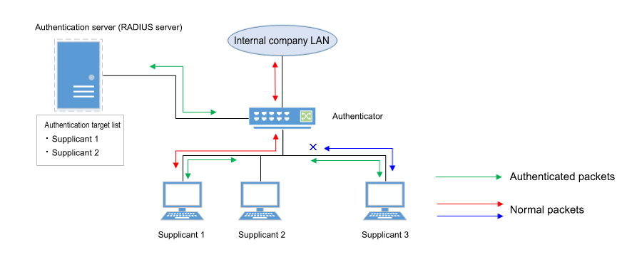
2 Definition of Terms Used
- IEEE 802.1X
- The authentication standard used when connecting to the LAN.
- Authenticator
A device or software that authenticates a supplicant connected to a LAN/SFP port.
It mediates between the supplicant and the authentication server, controlling access to the LAN according to the success or failure of authentication.
- Supplicant
- A device or software that connects to an authenticator and receives authentication.
- Authentication server
A device or software that authenticates a supplicant that is connected via the authenticator.
This manages authentication information such as user names, passwords, MAC addresses, and associated VLANs.
- EAP (Extended authentication protocol)
This is an authentication protocol that extends PPP, allowing various authentication methods to be used.
This is defined in RFC3748.
- EAP over LAN (EAPOL)
- This is a protocol for conveying EAP packets between the supplicant and the authenticator.
- EAP over Radius
- This is a protocol for conveying EAP packets between the authenticator and the authentication server (RADIUS server).
- EAP-MD5 (Message digest algorithm 5)
Client authentication using user name and password.
This uses an MD5 hash value to authenticate.
- EAP-TLS (Transport Layer Security)
This uses the digital certificates of the server and the client to authenticate.
With the transport layer encrypted, the digital certificates are exchanged and authenticated.
This is defined in RFC2716 and RFC5216.
- EAP-TTLS (Tunneled TLS)
This is an extended version of EAP-TLS.
This uses the digital signature of the server to establish a TLS communication route, and within this encrypted communication route uses a password to authenticate the client.
This is defined in RFC5281.
- EAP-PEAP (Protected EAP)
The principle of operation is equivalent to EAP-TTLS (the only difference is the protocol inside the encrypted tunnel).
This uses the digital signature of the server to establish a TLS communication route, and within this encrypted communication route uses a password to authenticate the client.
3 Function Details
The operating specifications for port authentication are shown below.
As port authentication functions, this product supports IEEE 802.1X authentication, MAC authentication, and Web authentication.
The following table shows the distinctive features of each authentication method.
Port authentication method features
| MAC authentication | IEEE 802.1X authentication | Web authentication | |
|---|---|---|---|
| Authenticated element | MAC address | User name and password (EAP-MD5, EAP-TTLS, EAP-PEAP) | User name and password |
| Authenticated object (supplicant) | Device | Device or user | Device or user |
| Functionality needed by supplicant | None | IEEE 802.1X authentication | Web browser |
| Operation when authenticating | None | User name and password entry (EAP-MD5, EAP-TTLS, EAP-PEAP) | User name and password entry |
This screen assumes a RADIUS server as the authentication server.
Note that the port authentication functionality of this product has the following limitations.
- The number of supplicants that can be authenticated is one for each port in single host mode or multi-supplicant mode; for multi-supplicant mode, the maximum is 1024 for the entire system.
- It cannot be used on a private VLAN port.
- It cannot be used on a voice VLAN port.
- If port authentication is enabled, a spanning tree topology change will occur according to the authentication result.
If you want to avoid this, specify “spanning-tree edgeport” for the authentication port to which the supplicant will be connected.
- Web authentication can be used only in multi-supplicant mode.
- Web authentication cannot be used together with a guest VLAN.
- When using the stack function, the Web Authentication screen customization file references a file saved on the main switch.
- When using the stack function, if a member switch is added, the authentication information of the supplicant connected to the logical interface is cleared.
- When using the stack function, if the main switch is demoted to a member switch status, authentication information is cleared from connected supplicants.
- Trunk ports can only be used in the multi-supplicant mode.
- Trunk ports cannot use dynamic or guest VLANs.
- If L2MS functionality is shared via a trunk port, the presence of a native VLAN must be specified.
- If the following supplicant VLAN is changed by a dynamic VLAN, then the authentication function may not work properly.
- DHCP server
- L2MS compatible device
3.1 IEEE 802.1X authentication
IEEE 802.1X authentication uses EAP to authenticate in units of devices or users.
The supplicant receiving authentication must support IEEE 802.1X authentication.
This product operates as an authenticator that communicates with the supplicant via EAP over LAN and communicates with the RADIUS server via EAP over RADIUS.
The authentication process itself occurs directly between the supplicant and the RADIUS server.
As authentication methods, this product supports EAP-MD5, EAP-TLS, EAP-TTLS, and EAP-PEAP.
The features of each authentication method are shown in the following table.
Features of each authentication method
| Client authentication method | Server authentication method | Ease of implementation | Degree of safety | |
|---|---|---|---|---|
| EAP-MD5 | User name and password entry | No authentication | Easy | Low |
| EAP-TLS | Client certificate | Server certificate | Complex | High |
| EAP-TTLS | User name and password entry | Server certificate | Medium | Medium |
| EAP-PEAP | User name and password entry | Server certificate | Medium | Medium |
Make settings for the supplicant and the RADIUS server as appropriate for the authentication method you use.
The basic procedure for IEEE 802.1X authentication is shown in the following diagram.
Basic procedure for IEEE 802.1X authentication
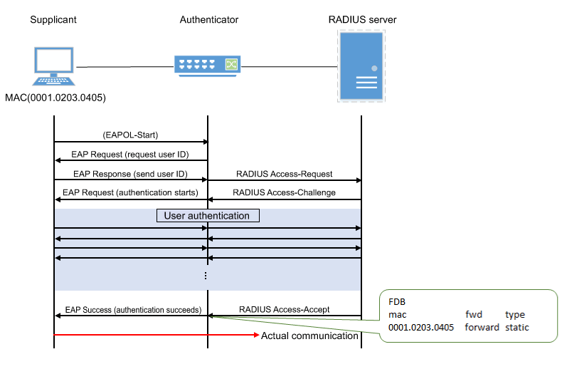
The supplicant is connected to the LAN, and transmits a communication start message (EAPOL-Start) message to start authentication.
When authentication succeeds, authentication success (Success) notification is sent to the supplicant, and the supplicant’s MAC address is registered in the FDB, allowing the supplicant to access the network.
If authentication fails, an authentication failure (Failure) notification is sent to the supplicant, and network access is denied for the supplicant.
(Even without authentication, it is possible to allow access to a specific VLAN if a guest VLAN has been specified.)
3.2 MAC authentication
MAC authentication uses the MAC address of a device to authenticate an individual device.
Since the supplicant does not need special functionality to be authenticated, authentication is possible even for devices that do not support IEEE 802.1X.
The basic procedure for MAC authentication is shown in the following diagram.
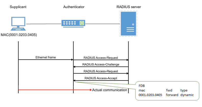
When this product receives any Ethernet frame from the supplicant, it queries the RADIUS server with the supplicant’s MAC address as the user name and password.
EAP-MD5 is used as the authentication mode between this product and the RADIUS server.
When authentication succeeds, the supplicant’s MAC address is registered in the FDB, allowing the supplicant to access the network.
However, it can be registered as a static entry by specifying MAC authenticated static registration (using the auth-mac static command).
If authentication fails, the supplicant is denied network access.
(Even without authentication, it is possible to allow access to a specific VLAN if a guest VLAN has been specified.)
The supplicant’s MAC address must be registered as the user name and password in the RADIUS server, in one of the following formats.
- XX-XX-XX-XX-XX-XX (hyphen delimited)
- XX:XX:XX:XX:XX:XX (colon delimited)
- XXXXXXXXXXXX (not delimited)
This product lets you use the auth-mac auth-user command to change the format of the MAC address query that is made to the RADIUS server.
Specify the appropriate command according to the format of the MAC addresses that are registered in the RADIUS server.
3.3 Web authentication
Web authentication is a function that authenticates a user when a user name and password are entered from the supplicant’s web browser.
HTTP is supported as the communication method between the web browser and the switch.
Because web authentication performs authentication by communicating via HTTP, it is necessary for IP communication between this product and the supplicant to be possible even before authentication.
Either the DHCP server must assign an IP address to the supplicant, or the supplicant must specify an IP address statically.
Web authentication operates only in multi-supplicant mode.
Also, this cannot be used together with a guest VLAN.
The basic procedure for web authentication is shown in the following diagram.
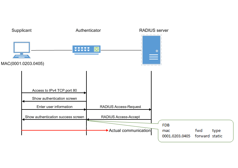
This product queries the RADIUS server using the user name and password that were entered in the supplicant’s web browser.
EAP-MD5 is used as the authentication mode between this product and the RADIUS server.
When authentication succeeds, the supplicant’s MAC address is registered in the FDB, allowing the supplicant to access the network.
If authentication fails, the supplicant is denied network access.
3.3.1 Operations on the supplicant
When the supplicant’s web browser accesses IPv4 TCP port 80, the following authentication screen appears.
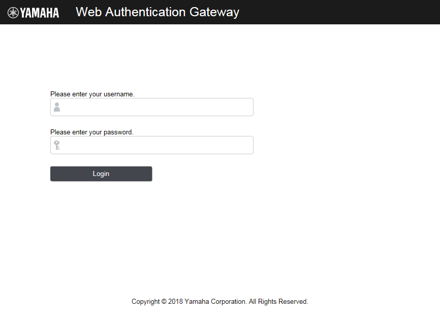
To be authenticated, enter a user name and password, and click the [Login] button.
The supplicant’s MAC address is registered in the FDB, allowing the supplicant to access the network.
If authentication fails three times in succession, authentication is temporarily restricted.
3.3.2 Customizing the authentication screen
The displayed content on the Web authentication screen (the edited HTML, CSS and image files) can be copied to this product, and the following parts can be customized.
Note that we cannot provide support for how to code in HTML/CSS or what formatting to use, or for any troubles that may occur due to modifications to the code.
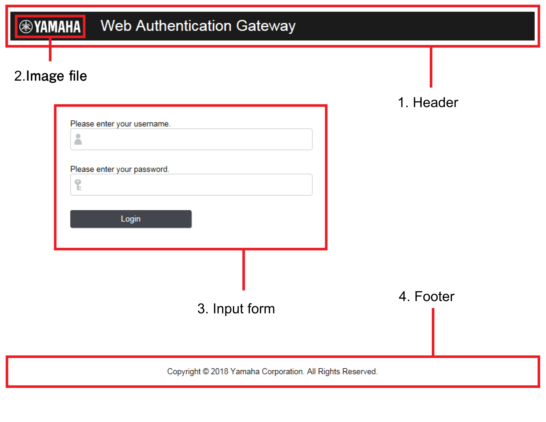
- Header
The header section includes the “header.html” and “style.css” files. Edit these files and copy them to this product in order to customize them. - Image file
Copy the image provided to this product in order to modify it. - Input form
The display style used for the input form is defined in the “style.css” file. Although the text cannot be changed, you can edit the “style.css” file and copy it to this product in order to change the input form’s design. - Footer
The footer section includes the “footer.html” and “style.css” files. Edit these files and copy them to this product in order to customize them.
The following explains how to modify the Web authentication screen.
3.3.2.1 Preparing the authentication screen customization files
The following files are used to customize the Web authentication screen.
- header.html
- footer.html
- logo.png
- style.css
Use the Web browser to access the “header.html”, “footer.html” and “style.css” files from the switch.
For example if the IP address of the switch is 192.168.100.240, you can use the following URL to access the file from a PC connected to a port on which Web authentication is enabled, and then use the browser’s “Save as” command to save the file on the PC.
- http://192.168.100.240/web-auth/header.html
- http://192.168.100.240/web-auth/footer.html
- http://192.168.100.240/web-auth/style.css
When saving, specify the extension as “.html” or “.css” and specify the character encoding as “UTF-8.”
For the image file logo.png, prepare a desired image file on the PC, and save it with the file name logo.png.
The maximum file size is 1 MB.
3.3.2.2 Editing the authentication screen customization files
Edit the above-mentioned HTML and CSS files as appropriate on your PC.
You are free to edit each file in accordance with HTML and CSS specifications, but please note the following points.
- The only image file that can be referenced from the “header.html” and “footer.html” files is “logo.png”.
- The extension of the CSS file must be “.html” or “.css” and the character encoding must be consistent with UTF-8.
3.3.2.3 Placing the authentication screen customization files
When you have prepared the files, place them in /model name/startup-config/web-auth/ on the SD card.
After placing the files, use the copy auth-web custom-file command or the copy startup-config command to copy the authentication screen customization files to the switch.
If the following files exist in the folder hierarchy in which the currently-running CONFIG is saved, they are used to generate the Web authentication screen.
You can determine the currently-running CONFIG number by using the show environment command. Even if the switch started up using the CONFIG on the SD card, you can customize the Web authentication screen by placing these files in /model name/startup-config/web-auth/ on the SD card.
- header.html
This is used as the header section referenced from the authentication screen. If this file does not exist, the original “header.html” is used.
- footer.html
This is used as the footer section referenced from the authentication screen. If this file does not exist, the original “footer.html” is used.
- logo.png
This is used as the logo in the upper left of the authentication screen. If this file does not exist, the original Yamaha logo is shown.
- style.css
This is used as the “style.css” referenced from the authentication screen. If this file does not exist, the original style.css is used.
When you have finished placing the edited files, check the display by using your browser to access the Web authentication screen.
If you need to make additional changes, edit the files on your PC, and transfer them again.
3.3.2.4 Canceling customization
If you decide to cancel customization of the authentication screen, delete the customization files from the folder in which the currently-running CONFIG is saved. You will revert to the original authentication screen.
To delete the files, you can use the erase auth-web custom-file command or the erase startup-config command.
However, since the erase startup-config command also deletes files such as config.txt, you should first copy files such as config.txt to an SD card etc. as a backup.
3.3.3 Linking to a DHCP Server
If a dynamic VLAN web authentication is used, IP addresses can be updated smoothly by using an internal DHCP server. (Note: Only for models that support DHCP servers)
If the DHCP server operation type setting (server-type command) is updated to support web authentication, then successfully authenticated supplicant IP addresses can be updated before finishing the lease period.
However, both DHCP servers specified for use before and after authentication must be within the same switch.
3.4 Using multiple authentication functions
This product allows using a combination of IEEE 802.1X authentication, MAC authentication, and/or Web authentication at the same port.
When switches are used in combination, each switch is successively authenticated in the authentication order specified using the auth order command. With default settings, IEEE 802.1X authentication is prioritized.
For web authentication, switches are authenticated by entering an ID and password in the Web Authentication screen, where the authentication method is changed to web authentication.
If multiple authentication methods are used simultaneously, basic operations are as follows.
If both IEEE 802.1X authentication and MAC authentication are used, with IEEE 802.1X authentication prioritized
If both IEEE 802.1X authentication and MAC authentication are used, with MAC authentication prioritized
If both web authentication and IEEE 802.1X/MAC authentication are used
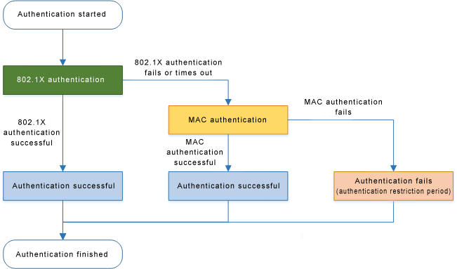
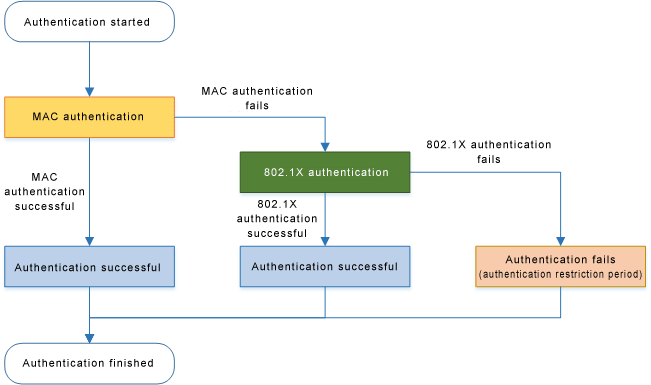
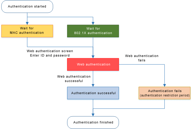
note
- If authentication succeeds with any one of the methods, authentication has succeeded.
- If the reauthentication setting is enabled, then reauthentication is performed using the method with which authentication succeeded.
- If multiple authentication methods are used, forwarding control settings received via an unauthenticated port will be discarded.
- If both IEEE 802.1X authentication and MAC authentication are being used and an EAPOL start signal is received from an unauthenticated supplicant, authentication will switch to IEEE 802.1X authentication even if MAC authentication is already in progress.
- If both IEEE 802.1X authentication and MAC authentication are being used, even if the first authentication method fails, authentication will switch to the next authentication method without entering the restriction period.
- If both IEEE 802.1X authentication and MAC authentication are being used and any Ethernet frame is received from a supplicant, the product transmits an EAP request.
- If Web authentication is also being used, unauthenticated supplicants are registered in FDB as static/discard.
3.5 Host mode
This product lets you select the host mode for the port authentication function.
Host mode indicates how an applicable supplicant’s communication will be permitted on the authentication port.
This product lets you choose from the following host modes.
- Single host mode
This mode permits communication for only one supplicant for each LAN/SFP port.
Communication is permitted only for the first supplicant that successfully authenticates.
- Multi-host mode
This mode permits communication for multiple supplicants for each LAN/SFP port.
When a supplicant successfully authenticates and communication is permitted, another supplicant that is connected to the same LAN/SFP port and that successfully authenticates is also permitted to communicate on the same VLAN.
- Multi-supplicant
This mode permits communication for multiple supplicants for each LAN/SFP port.
Each supplicant is distinguished by its MAC address, permitting communication in units of supplicants.
When using dynamic VLAN functions, you can specify the VLAN for each supplicant.
3.6 Dynamic VLANs
This product supports dynamic VLANs using IEEE 802.1X, MAC, or Web authentication.
Dynamic VLAN is a function that changes the authentication port’s associated VLAN according to the VLAN attribute values in authentication information in notifications received from the RADIUS server.
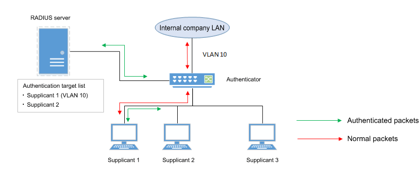
As shown in the illustration above, if a port’s associated VLAN is 1, and the received authentication data has a VLAN attribute of 10, then following successful authentication, the authentication port’s associated VLAN is 10, and communication on VLAN 10 is permitted.
For the RADIUS server, make settings so that the authentication information sent from the server includes the following attribute values.
- Tunnel-Type = VLAN (13)
- Tunnel-Medium-Type = IEEE-802 (6)
- Tunnel-Private-Group-ID = VLAN ID
If a dynamic VLAN is used, the following actions will occur in respective host modes.
- Single host mode
The authentication port’s associated VLAN is changed according to the VLAN attribute value of the supplicant that successfully authenticates.
- Multi-host mode
The authentication port’s associated VLAN is changed according to the VLAN attribute value of the supplicant that successfully authenticates.
Other supplicants that are connected to the same port are also permitted to communicate on the same VLAN.
- Multi-supplicant mode
The authentication port’s associated VLAN is changed according to the VLAN attribute value of the supplicant that successfully authenticates.
You can specify the VLAN for each supplicant.
3.7 VLAN for unauthenticated or failed-authentication ports
This product’s IEEE 802.1X authentication and MAC authentication allows you to specify a guest VLAN so that unauthenticated ports or ports that failed authentication will be assigned to a specific VLAN.
In multi-supplicant mode, you can specify this for each supplicant.
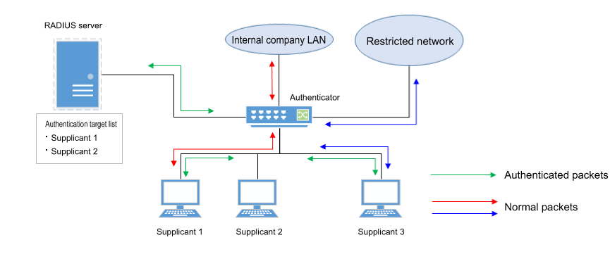
This is useful when you want to provide partial functionality on a limited network even to a supplicant that has not succeeded in authenticating, as shown in the illustration above.
3.8 EAP pass-through function
You can switch between enable and disable for EAP pass-through and configure whether EAPOL frames are to be forwarded.
The authentication function will be prioritized for interfaces on which the 802.1X authentication function is enabled, and EAP pass-through will not be applied.
3.9 Attribute values sent to the RADIUS server
The NAS-Identifier attribute value can be notified to the RADIUS server.
The character string set with the auth radius attribute nas-identifier command is sent to the RADIUS server as the NAS-Identifier attribute value.
4 Related Commands
The related commands are shown below.
For details on the commands, refer to the Command Reference.
List of related commands
| Operations | Operating Commands |
|---|---|
| Set IEEE 802.1X authentication function for the entire system | aaa authentication dot1x |
| Set MAC authentication function for the entire system | aaa authentication auth-mac |
| Set Web authentication function for the entire system | aaa authentication auth-web |
| Set IEEE 802.1X authentication function operating mode | dot1x port-control |
| Set unauthenticated port forwarding control for IEEE 802.1X authentication | dot1x control-direction |
| Set number of retransmitted EAPOL packets | dot1x max-auth-req |
| Set MAC authentication function | auth-mac enable |
| Set MAC address format setting for MAC authentication | auth-mac auth-user |
| MAC authenticated stack registration setting | auth-mac static |
| Set Web authentication function | auth-web enable |
| Set redirect-destination URL following successful Web authentication | auth-web redirect-url |
| Copy Web authentication screen customization files | copy auth-web custom-file |
| Delete Web authentication screen customization files | erase auth-web custom-file |
| Set host mode | auth host-mode |
| Authentication order setting | auth order |
| Set reauthentication | auth reauthentication |
| Set dynamic VLAN | auth dynamic-vlan-creation |
| Set guest VLAN | auth guest-vlan |
| Set restriction period following failed authentication | auth timeout quiet-period |
| Set reauthentication interval | auth timeout reauth-period |
| Set response wait time for the entire RADIUS server | auth timeout server-timeout |
| Set response wait time for the supplicant | auth timeout supp-timeout |
| Set RADIUS server host | radius-server host |
| Set response wait time for a single RADIUS server | radius-server timeout |
| Set number of times to retransmit request to RADIUS server | radius-server retransmit |
| Set shared password for RADIUS server | radius-server key |
| Set availability time restriction for RADIUS server | radius-server deadtime |
| Setting the NAS-Identifier attribute to notify the RADIUS server | auth radius attribute nas-identifier |
| Show port authentication status | show auth status |
| Show RADIUS server setting status | show radius-server |
| Show supplicant status | show auth supplicant |
| Show statistical information | show auth statistics |
| Clear statistical information | clear auth statistics |
| Clear authentication state | clear auth state |
| Set time at which authentication state is cleared (system) | auth clear-state time |
| Set time at which authentication state is cleared (interface) | auth clear-state time |
| EAP pass-through settings | pass-through eap |
5 Examples of Command Execution
5.1 Set IEEE 802.1X authentication
Make settings so that IEEE 802.1X authentication can be used.
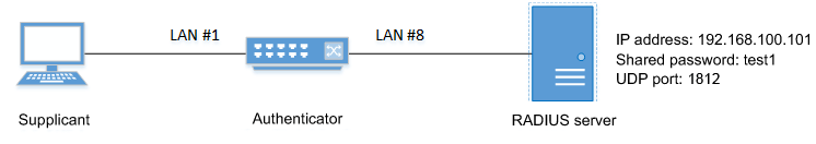
- We will use LAN port #1 as the authentication port to which the supplicant is connected.
- We will set the host mode to multi-supplicant mode.
- We will use VLAN #10 as the guest LAN.
- We will use 192.168.100.101 as the IP address of the RADIUS server that is connected.
- Define VLAN #10 as the guest VLAN.
Yamaha(config)#vlan database
Yamaha(config-vlan)#vlan 10               ... (VLAN #10 definition)
Yamaha(config-vlan)#exit
- Enable the IEEE 802.1X authentication function for the entire system.
Yamaha(config)#aaa authentication dot1x
- Set IEEE 802.1X authentication for LAN port #1.
Yamaha(config)#interface port1.1
Yamaha(config-if)#dot1x port-control auto          ... (Set IEEE 802.1X authentication operating mode to auto)
Yamaha(config-if)#auth host-mode multi-supplicant  ... (Set host mode to multi-supplicant mode)
Yamaha(config-if)#auth guest-vlan 10               ... (Set guest VLAN as VLAN #10)
Yamaha(config-if)#exit
- Set RADIUS server settings.
Yamaha(config)#radius-server host 192.168.100.101 key test1 (Set host as 192.168.100.101 and shared password as “test1”) - Check RADIUS server settings.
Yamaha#show radius-server
Server Host : 192.168.100.101
  Authentication Port : 1812
  Secret Key          : test1
  Timeout             : 5 sec
  Retransmit Count    : 3
  Deadtime            : 0 min
- Check port authentication settings.
Yamaha#show auth status
[System information]
  802.1X Port-Based Authentication : Enabled
  MAC-Based Authentication         : Disabled
  WEB-Based Authentication         : Disabled

  Clear-state time : Not configured

  Redirect URL :
    Not configured

  RADIUS server address :
    192.168.100.101 (port:1812)

[Interface information]
  Interface port1.1 (up)
    802.1X Authentication   : Force Authorized (configured:auto)
    MAC Authentication      : Disabled (configured:disable)
    WEB Authentication      : Enabled (configured:disable)
    Host mode               : Multi-supplicant
    Dynamic VLAN creation   : Disabled
    Guest VLAN              : Enabled (VLAN ID:10)
    Reauthentication        : Disabled
    Reauthentication period : 3600 sec
    MAX request             : 2 times
    Supplicant timeout      : 30 sec
    Server timeout          : 30 sec
    Quiet period            : 60 sec
    Controlled directions   : In (configured:both)
    Protocol version        : 2
    Clear-state time        : Not configured
5.2 Set MAC authentication
Make settings so that MAC authentication can be used.
- We will use LAN port #1 as the authentication port to which the supplicant is connected.
- We will set the host mode to multi-supplicant mode.
- We will use 192.168.100.101 as the IP address of the RADIUS server that is connected.
- Enable the MAC authentication function for the entire system.
Yamaha(config)#aaa authentication auth-mac
- Set MAC authentication for LAN port #1.
Yamaha(config)#interface port1.1
Yamaha(config-if)#auth-mac enable                  ... (Enable MAC authentication)
Yamaha(config-if)#auth host-mode multi-supplicant  ... (Set host mode to multi-supplicant mode)
Yamaha(config-if)#exit
- Set RADIUS server settings.
Yamaha(config)#radius-server host 192.168.100.101 key test1 (Set host as 192.168.100.101 and shared password as “test1”) - Check RADIUS server settings.
Yamaha#show radius-server
Server Host : 192.168.100.101
  Authentication Port : 1812
  Secret Key          : test1
  Timeout             : 5 sec
  Retransmit Count    : 3
  Deadtime            : 0 min
- Check port authentication settings.
Yamaha#show auth status
[System information]
  802.1X Port-Based Authentication : Disabled
  MAC-Based Authentication         : Enabled
  WEB-Based Authentication         : Disabled

  Clear-state time : Not configured

  Redirect URL :
    Not configured

  RADIUS server address :
    192.168.100.101 (port:1812)

[Interface information]
  Interface port1.1 (up)
    802.1X Authentication   : Force Authorized (configured:-)
    MAC Authentication      : Enabled (configured:enable)
    WEB Authentication      : Disabled (configured:disable)
    Host mode               : Multi-supplicant
    Dynamic VLAN creation   : Disabled
    Guest VLAN              : Disabled
    Reauthentication        : Disabled
    Reauthentication period : 3600 sec
    MAX request             : 2 times
    Supplicant timeout      : 30 sec
    Server timeout          : 30 sec
    Quiet period            : 60 sec
    Controlled directions   : In (configured:both)
    Protocol version        : 2
    Clear-state time        : Not configured
    Authentication status   : Unauthorized
5.3 Set Web authentication
Make settings so that Web authentication can be used.
- We will use LAN port #1 as the authentication port to which the supplicant is connected.
- We will assume that 192.168.100.10 the IP address of the supplicant.
- We will use 192.168.100.101 as the IP address of the RADIUS server that is connected.
- Assign an IP address to the authenticator for IP communication.
Yamaha(config)#interface valn1
Yamaha(config-if)#ip address 192.168.100.240/24
Yamaha(config-if)#exit
- Enable the Web authentication function for the entire system.
Yamaha(config)#aaa authentication auth-web
- Set Web authentication for LAN port #1.
Yamaha(config)#interface port1.1
Yamaha(config-if)#auth host-mode multi-supplicant     ... (Set host mode to multi-supplicant mode)
Yamaha(config-if)#auth-web enable                     ... (Enable web authentication)
Yamaha(config-if)#exit
- Set RADIUS server settings.
Yamaha(config)#radius-server host 192.168.100.101 key test1 (Set host as 192.168.100.101 and shared password as “test1”) - Check RADIUS server settings.
Yamaha#show radius-server
Server Host : 192.168.100.101
  Authentication Port : 1812
  Secret Key          : test1
  Timeout             : 5 sec
  Retransmit Count    : 3
  Deadtime            : 0 min
- Check port authentication settings.
Yamaha#show auth status
[System information]
  802.1X Port-Based Authentication : Disabled
  MAC-Based Authentication         : Disabled
  WEB-Based Authentication         : Enabled

  Clear-state time : Not configured

  Redirect URL :
    Not configured

  RADIUS server address :
    192.168.100.101 (port:1812)

[Interface information]
  Interface port1.1 (up)
    802.1X Authentication   : Force Authorized (configured:-)
    MAC Authentication      : Disabled (configured:disable)
    WEB Authentication      : Enabled (configured:enable)
    Host mode               : Multi-supplicant
    Dynamic VLAN creation   : Disabled
    Guest VLAN              : Disabled
    Reauthentication        : Disabled
    Reauthentication period : 3600 sec
    MAX request             : 2 times
    Supplicant timeout      : 30 sec
    Server timeout          : 30 sec
    Quiet period            : 60 sec
    Controlled directions   : In (configured:both)
    Protocol version        : 2
    Clear-state time        : Not configured
6 Points of Caution
Using dynamic VLAN in multi-supplicant mode will consume internal resources.
These resources are also used by the ACL and QoS functions. There may not be enough resources according to the settings.
Use caution, since communications may not be possible if there are not enough resources, even though authentication might succeed.
7 Related Documentation
- SWX3220 Series Technical Data (Basic Functions)
- Interface control functions
- Port security functions
Port security functions
1 Function Overview
Port security is a function that limits communication to only permitted terminals, preventing access from illegal terminals.
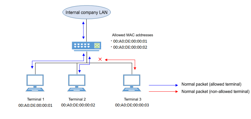
2 Definition of Terms Used
None
3 Function Details
For ports on which the port security function is enabled, you can pre-register the MAC address of a terminal for which you want to permit communication, thereby allowing communication only for permitted terminals.
Conversely, if there is access from a terminal that is not registered (an illegal terminal), this is considered illegal access, and the packets are discarded.
Depending on the settings, the corresponding port can also be shut down.
The port security function cannot be used simultaneously with the port authentication function.
3.1 Limiting the terminals that can access
By enabling the port security function, and using the port-security mac-address command to register the MAC addresses of only the terminals for which you want to allow communication, you can limit the terminals that are allowed access.
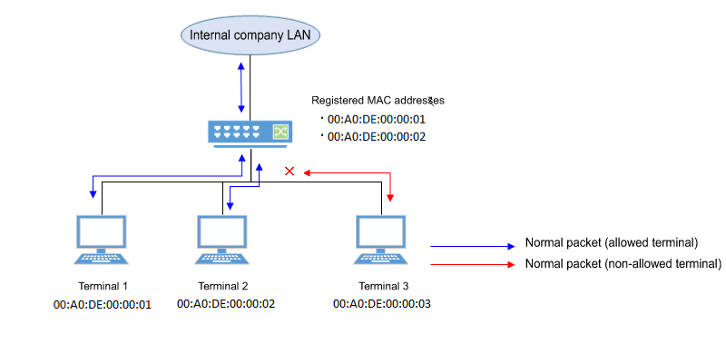
4 Related Commands
The related commands are shown below.
For details on the commands, refer to the Command Reference.
List of related commands
| Operations | Operating Commands |
|---|---|
| Set port security function | port-security enable |
| Register allowed MAC addresses | port-security mac-address |
| Set operation for when security violation occurs | port-security violation |
| Show port security status | show port-security status |
5 Examples of Command Execution
5.1 Limiting the terminals that can access
Manually specify the MAC address so that only the permitted terminal can communicate.
- Enable port security on LAN port #1.
Yamaha(config)#interface port1.1
Yamaha(config-if)#port-security enable
- Register the MAC address that you want to permit.
Yamaha(config)#port-security mac-address 00A0.DE00.0001 forward port1.1 vlan 1
Yamaha(config)#port-security mac-address 00A0.DE00.0002 forward port1.1 vlan 1
- Check the port security status.
Yamaha#show port-security status
 Port      Security  Action     Status    Last violation
 --------- --------- ---------- --------- ---------------------
 port1.1   Enabled   Discard    Normal    00A0.DE00.0003
 port1.2   Disabled  Discard    Normal
 port1.3   Disabled  Discard    Normal
 port1.4   Disabled  Discard    Normal
 port1.5   Disabled  Discard    Normal
 port1.6   Disabled  Discard    Normal
 port1.7   Disabled  Discard    Normal
 port1.8   Disabled  Discard    Normal
 port1.9   Disabled  Discard    Normal
 port1.10  Disabled  Discard    Normal
6 Points of Caution
- Use the no shutdown command to recover the port that has shut down due to illegal access.
The status of the show port-security status command will not return to normal until the port links up. (The status will remain in shutdown state.)
- If the wrong port is specified with the port-security mac-address command, traffic and violation frames will not be correctly detected.
7 Related Documentation
None
- SWX3220 Series Technical Data (Basic Functions)
- Layer 2 functions
- Forwarding database (FDB)
Forwarding database (FDB)
1 Function Overview
The Forwarding Database (subsequently referred to as the FDB) manages the combination of destination MAC addresses, transmission ports, and VLANs.
This product uses the FDB to determine the forwarding destination port for the received frames.
- Enable/disable acquisition function
- Timeout adjustment for FDB entries acquired
- Timeout clear for FDB entries acquired
- Manual registration of FDB entries (static entries)
2 Definition of Terms Used
- FDB
Abbreviation of “Forwarding Database.”
This database manages the combination of destination MAC address, transmission port, and VLAN.
- FDB entry
- This is data registered in the FDB, and consists of multiple elements.
3 Function Details
3.1 FDB entry
On this product, the contents listed in the table below are registered as a single entry in the FDB.
Up to 32,768 addresses can be registered, including addresses registered via automatic acquisition and manual registration.
| Element managed | Description | |
|---|---|---|
| MAC address | Device MAC addresses can be either unicast or multicast. | |
| VLAN-ID (FID) | The VLAN ID to which a device is associated. This is a value from 1–4094. | |
| Forwarding destination interface ID | The interface on which the device exists. LAN/SFP ports are static/LACP logical interfaces. | |
| Action | The method of processing the frame addressed to the device. There are two processing methods, “discard” and “forward”. | |
| Entry registration type | dynamic | Entries registered through automatic acquisition |
| static | Entries registered manually via commands | |
| multicast | Entries acquired by IGMP/MLD Snooping | |
3.1.1 MAC address
This is one of the FDB key items; the VLAN-ID and MAC address are combined to become the record key.
Operation differs depending on whether the MAC address is unicast or multicast.
- Unicast
Since the forwarding destination interface ID must be uniquely determined for a given record key, duplication is not allowed.
(Multiple combinations of the same VLAN-ID and MAC address do not exist.)
- Multicast
Multiple forwarding destination interface IDs may exist for a given key record.
In this case, frames are sent to multiple forwarding destination interface IDs.
The MAC addresses of all received frames can be acquired, and the source MAC address is acquired and registered in the FDB.
However, if the transmission source MAC address is multicast, this is considered an invalid frame and is discarded without being registered.
Each VLAN interface created internally consumes one FDB entry.
Automatically acquired MAC address information is maintained until the ageing timeout.
If multiple multicast MAC addresses are specified, all are considered as one in this case.
VLAN  port    mac             fwd      type    timeout
   1  port1.1 0100.0000.1000  forward  static       0
   1  port1.2 0100.0000.1000  forward  static       0
   1  port1.3 0100.0000.1000  forward  static       0
   1  port1.4 0100.0000.1000  forward  static       0
   1  port1.5 0100.0000.1000  forward  static       0
   1  port1.6 0100.0000.1000  forward  static       0
3.1.2 VLAN-ID
MAC address acquisition is done per VLAN, and the MAC address and VLAN are managed in the FBD as a pair.
For different VLANs, identical MAC addresses are also acquired.
3.1.3 Forwarding destination interface ID
The following IDs are registered.
- LAN/SFP port (port)
- Static/LACP logical interface (sa,po)
3.1.4 Action
This defines the action for a received frame that matches a key record.
If the MAC address is unicast, the actions are as follows.
- forward ... Forward to the forwarding destination interface ID.
- discard ... Discard without forwarding.
If the MAC address is multicast, the actions are as follows.
- forward ... Forward to the forwarding destination interface ID.
- discard ... Cannot be specified.
(The discard setting cannot be made if the MAC address is multicast.)
3.1.5 Registration types
- dynamic ... Registered and deleted automatically. The registration result does not remain in the config settings file.
- static ... Registered and deleted manually, and therefore remains in the config settings file.
- multicast ... Automatically registered and deleted by the IGMP/MLD snooping function. The registration result does not remain in the config settings file.
3.2 Automatic MAC address acquisition
Automatic MAC address acquisition refers to the active creation of FBD entries based on the information for the source MAC address of the received frame, and the reception port.
Entries registered through automatic acquisition are called “dynamic entries”.
A timer (ageing time) is used to monitor individual entries.
Entries for MAC addresses that have not received frames within a certain amount of time will be automatically deleted from FDB entries by an aging timer.
This prevents invalid device entries from being left over in the FDB due to power shutoff, being moved and so on.
If a frame is received within the specified amount of time, the monitoring timer will be reset.
The control specifications for automatic acquisition are shown below.
- Automatic MAC address acquisition can be enabled or disabled using the mac-address-table learning command. The setting is enabled by default.
- If automatic acquisition is changed from enabled to disabled, all dynamic entries that have been learned will be deleted. The acquisition function “disable” setting is useful when you want to flood all ports with all received frames.
- Aging timer settings for dynamic entries are specified using mac-address-table ageing-time command.
This value is set to 300 seconds by default.
- The actual time when entries are deleted by the aging time occurs within double the seconds specified as the timer setting value.
- Clear the dynamic entries that have been acquired by using the clear mac-address-table dynamic command. The entire contents of the FDB can be cleared at once; or a VLAN number can be specified and all MAC addresses acquired by that VLAN can be cleared from the FDB. Specifying the port number will clear all MAC addresses from the FDB that were acquired from that port.
- Use the show mac-address-table command to check the automatic acquisition status.
3.3 Setting MAC addresses manually
In addition to automatic acquisition using received frames, MAC addresses can be set on this product by using user commands.
Entries that have been registered by using commands are called “static entries”.
The specifications for manual settings are shown below.
- Use the mac-address-table static command to register static entries.
- When registering static entries, dynamic acquisition will not be performed on the corresponding MAC addresses.
Entries that have already been acquired will be deleted from the FDB, and will be registered as static entries.
- Use the no mac-address-table static command to delete static entries.
- Either “forward” or “discard” can be specified for the destination MAC address of a received frame.
- When forwarding is specified, either the LAN/SFP port forwarding destination or the static/LACP logical interface can be specified.
- When discarding is specified, frames received by the MAC address will not be forwarded to any port, and will be discarded.
- If registering a multicast MAC address, you cannot specify “discard.”
Also, the following MAC addresses cannot be registered.
- 0000.0000.0000
- 0100.5e00.0000–0100.5eff.ffff
- 0180.c200.0000–0180.c200.000f
- 0180.c200.0020–0180.c200.002f
- 3333.0000.0000–3333.ffff.ffff
- ffff.ffff.ffff
4 Related Commands
4.1 List of related commands
| Operations | Operating Commands |
|---|---|
| Enable/disable MAC address acquisition function | mac-address-table learning |
| Set dynamic entry ageing time | mac-address-table ageing-time |
| Clear dynamic entry | clear mac-address-table dynamic |
| Register static entry | mac-address-table static |
| Delete static entry | no mac-address-table static |
| Refer to MAC address table | show mac-address-table |
5 Examples of Command Execution
5.1 Referring to the FDB
Yamaha#show mac-address-table
VLAN  port     mac             fwd      type     timeout
   1  port1.2  00a0.de11.2233  forward  static        0
   1  port1.1  1803.731e.8c2b  forward  dynamic     300
   1  port1.1  782b.cbcb.218d  forward  dynamic     300
5.2 Deleting a dynamic entry
Deleting an FDB entry registered in the FBD (MAC address 00:a0:de:11:22:33)
Yamaha#clear mac-address-table dynamic address 00a0.de11.2233
5.3 Changing the dynamic entry ageing time
This example shows how to change the dynamic entry ageing time to 400 seconds.
Yamaha(config)#mac-address-table ageing-time 400
5.4 Registering a static entry
This example shows how frames addressed to a device associated with VLAN #10 (MAC address 00:a0:de:11:22:33) can be forwarded to LAN port 2 (port1.2).
Yamaha(config)#mac-address-table static 00a0.de11.2233 forward port1.2 vlan 10
This example shows how to discard the frames sent to a device associated with VLAN #10 (MAC address 00:a0:de:11:22:33).
Specifying the interface name (“port1.2” in the example) will have no effect on operations. Since this cannot be omitted, specify the LAN/SFP port.
Yamaha(config)#mac-address-table static 00a0.de11.2233 discard port1.2 vlan 10
5.5 Deleting a static entry
This example shows how to delete the forwarding settings sent to a device associated with VLAN #10 (MAC address 00:a0:de:11:22:33).
Yamaha(config)#no mac-address-table static 00a0.de11.2233 forward port1.2 vlan 10
6 Points of Caution
If the l2-unknown-mcast command is configured to discard unknown multicast frames, using the mac-address-table static command to passively forward a multicast MAC address will have no effect when registered.
7 Related Documentation
None
VLAN
1 Function Overview
VLAN (Virtual LAN) is technology that allows a LAN to be constructed virtually, without regard to the physical structure of connections.
This product lets you use VLANs to divide the LAN into multiple broadcast domains.
The VLANs that are supported by this product are shown below.
Supported VLAN types
| VLAN types | Summary |
|---|---|
| Port-based VLAN | Groups that can communicate are configured for each LAN/SFP port. |
| Tagged VLAN | Groups that can communicate are identified, based on the fixed-length tag information appended to the Ethernet frame. Multiple and different VLANs can be made to communicate by means of one LAN/SFP port. |
| Private VLAN | Groups that can communicate within the same VLAN can be divided up. This includes the following three VLAN types.
|
| Multiple VLAN | Each LAN/SFP port can be divided into multiple groups that can communicate. Refer to this information for multiple VLANs. |
| Voice VLAN | This allows audio and data to be handled separately on an access port. |
2 Definition of Terms Used
- Broadcast domain
This is a range in which broadcast frames can be delivered in a network, such as an Ethernet.
Devices that are connected by relaying a data link layer (MAC layer), such as switching hubs, can belong to the same broadcast domain.
A broadcast domain generally refers to the network in an Ethernet.
3 Function Details
3.1 Defining a VLAN ID
On product, a maximum of 255 VLANs can be defined, with VLAN IDs ranging from 2–4094. (ID #1 is used as the default VLAN ID.)
VLAN IDs are defined using the vlancommand, after the vlan database command is used to enter VLAN mode.
For details, refer to the Command Reference.
3.2 VLAN settings for the LAN/SFP ports
The following settings must be configured after defining the VLANs to use, in order to make use of VLAN on this product.
- LAN/SFP port mode settings
- VLAN associations for LAN/SFP ports
- The LAN/SFP ports on this product are set to one of the following modes.
- Access port
This is a port that handles untagged frames. It can be associated with one VLAN.
- Trunk port
This is a port that handles both tagged and untagged frames.
It can be associated with multiple VLANs, and is mainly used to connect switches to one another.
This product only supports IEEE 802.1Q. (Cisco ISL is not supported.)
- Access port
- Use the switchport mode command to set the LAN/SFP port mode.
When setting the trunk port, use the input filter (“ingress-filter”) to control whether frames not belonging to the specified VLAN ID will be handled.
- Input filter enabled: only frames set to the specified VLAN ID will be handled.
- Input filter disabled: all VLAN IDs will be handled.
- Use the show interface switchport command to check the LAN/SFP port setting mode.
- Use the switchport access vlan command to set which VLANs belong to the access port.
- Use the switchport trunk allowed vlan command to set which VLANs belong to the trunk port.
As the trunk port can be associated with multiple VLANs, use the “all”, “none”, “except”, “add” and “remove” settings as shown below.
- add
Adds the specified VLAN ID.
VLAN IDs that can be added are limited by the IDs that are defined by the VLAN mode.
- remove
Deletes the specified VLAN ID.
- all
Adds all VLAN IDs specified by the VLAN mode.
The VLAN IDs added by the VLAN mode can also be added after this command is executed.
- none
The trunk port will not be associated with any VLAN.
- except
Adds all other VLAN IDs except for the ones specified.
The VLAN IDs added by the VLAN mode can also be added after this command is executed.
- add
- A VLAN that uses untagged frames (native VLAN) can be specified for the trunk port.
- Tagged audio frames can be transferred by specifying a voice VLAN for an access port.
- Use the show vlan command to check which VLANs belong to a LAN/SFP port.
3.3 VLAN access control
This product provides an VLAN access map function, to control access to the VLAN.
The VLAN access map can be associated with a standard/extended IP access control list and a MAC address control list as VLAN ID filtering parameters.
The VLAN access map is operated using the commands shown below.
- Create VLAN access map: vlan access-map command
- Set VLAN access map parameters: match access-list command
- Assign VLAN access map: vlan filter command
- Show VLAN access map: show vlan access-map command
3.4 Default VLAN
The default VLAN is VLAN #1 (vlan1), which exists in this switch by default.
As the default VLAN is a special VLAN, it always exists and cannot be deleted.
The following operations can be used to automatically delete the relevant port from the default VLAN.
- Setting the VLAN for an access port
- Setting any VLAN other than the default as the native VLAN for the trunk port
- Setting the native VLAN for the trunk port to “none”
3.5 Native VLAN
A native VLAN is a VLAN that associates untagged frames received by the LAN/SFP port that was set as a trunk port.
Defining an LAN/SFP port as a trunk port will set the default VLAN (VLAN #1) as the native VLAN.
Use the switchport trunk native vlan command when specifying a certain VLAN as the native VLAN.
The native LAN can be set to none, when setting the relevant LAN/SFP port to not handle untagged frames. (Specify “none” in the switchport trunk native vlan command.)
3.6 Private VLAN
This product can configure a private VLAN for further dividing up groups that can communicate within the same subnet. The operating specifications are shown below.
- A private VLAN contains the following three VLAN types.
- Primary VLAN
This is the parent VLAN of the secondary VLAN.
Only one primary VLAN can be set per private VLAN.
- Isolated VLAN
This is a kind of secondary VLAN, which only sends traffic to a primary VLAN.
Only one primary VLAN can be set per private VLAN.
- Community VLAN
This is a kind of secondary VLAN, which only sends traffic to VLANs in the same community and to a primary VLAN.
Multiple community VLANs can be set for each private VLAN.
- Primary VLAN
- A primary VLAN may contain multiple promiscuous ports.
Access ports, trunk ports, or static/LACP logical interfaces are the ports that can be used as promiscuous ports.
- Only access ports can be used as host ports for a secondary VLAN (isolated VLAN, community VLAN).
- A secondary VLAN (isolated VLAN, community VLAN) can be associated with one primary VLAN.
Use the switchport private-vlan mapping command to create the association.
- An isolated VLAN can be associated with multiple promiscuous ports contained within a private VLAN.
- A community VLAN can be associated with multiple promiscuous ports contained within a private VLAN.
3.7 Voice VLAN
Voice VLAN is a function that can prevent audio from being adversely affected even when IP phone voice traffic is mixed with PC data traffic.

Some IP phones have two ports: a port for connection to the switch and a port for connection to the PC.
By connecting the switch to the IP phone, and the IP phone to the PC, it is possible to use one port of the switch to handle the IP phone audio traffic and the PC’s data traffic.
Using the voice VLAN function in this type of configuration allows the audio data and the PC data to be separated so that noise is less likely to occur on the IP phone, or to handle the audio data with a higher priority.
Voice VLAN settings are made by the switchport voice vlan command.
Set one of the following to be handled as voice traffic.
- Frames with the 802.1p tag
- Priority tag frames (802.1p tags with a VLAN ID of 0 and only the CoS value specified)
- Untagged frames
When tagged frames are handled as voice traffic, untagged frames are handled as data traffic.
By using LLDP, this product can automatically apply settings to a connected IP telephone.
The conditions for making automatic settings are as follows.
- LLDP-MED TLV transmission is enabled on the port for which voice VLAN is enabled.
- The connected IP phone supports settings via LLDP-MED.
If the above conditions are satisfied, and when an IP phone is connected to the corresponding port, voice VLAN information (tagged/untagged, VLAN ID, the CoS value to be used, DSCP value) are notified according to the Network Policy TLV of LLDP-MED when an IP phone is connected to the corresponding port.
The IP phone will transmit voice data according to the information that was provided to it from this unit.
The CoS value specified for the IP phone is set by the switchport voice cos command, and the DSCP value is set by the switchport voice dscp command.
In order to give priority to handling voice traffic, QoS settings (enable QoS, set trust mode) are also required.
The limitations of voice VLAN are as follows.
- It can be used only on a physical interface port that is assigned as an access port.
It cannot be used on a link aggregation logical interface or on a VLAN logical interface.
- The voice VLAN function and the port authentication function cannot be used together.
4 Related Commands
4.1 List of related commands
- The related commands are shown below.
Operations Operating Commands Enter VLAN mode vlan database Define VLAN interface, or change a predefined VLAN vlan Define a private VLAN private-vlan Set the secondary VLAN for a private VLAN private-vlan association Create VLAN access map vlan access-map Set VLAN access map parameters match Assign VLAN access map to VLAN vlan filter Set access port (untagged port) switchport mode access Set associated VLAN of an access port (untagged port) switchport access vlan Set trunk port (tagged port) switchport mode trunk Set associated VLAN for trunk port (tagged port) switchport trunk allowed vlan Set native VLAN for trunk port (tagged port) switchport trunk native vlan Set ports for private VLAN (promiscuous port, host port) switchport mode private-vlan Configure VLAN for private VLAN port and host port switchport private-vlan host-association Configure VLAN for private VLAN port and promiscuous port switchport private-vlan mapping Configure voice VLAN switchport voice vlan Set CoS value for voice VLAN switchport voice cos Set DSCP value for voice VLAN switchport voice dscp Show VLAN information show vlan Show private VLAN information show vlan private-vlan Show VLAN access map show vlan access-map Show VLAN access map filter show vlan filter
5 Examples of Command Execution
5.1 Port-based VLAN settings
In this example, a port-based VLAN is configured for this product in order to allow communication between hosts A–B and hosts C–D.
Port VLAN setting example
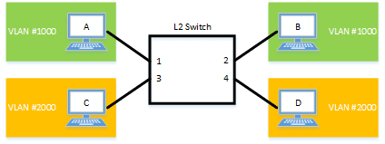
The LAN port settings for this product are as follows.
- Set LAN ports #1/#2 as access ports, and associate them with VLAN #1000.
- Set LAN ports #3/#4 as access ports, and associate them with VLAN #2000.
- Switch to VLAN mode using the vlan database command, and define two VLANs using the vlan command.
Yamaha(config)# vlan database … (Transition to VLAN mode)
Yamaha(config-vlan)# vlan 1000 … (Create VLAN #1000)
Yamaha(config-vlan)# vlan 2000 … (Create VLAN #2000)
Yamaha(config-if)# exit
- Set LAN ports #1–2 as access ports, and associate them with VLAN #1000.
Yamaha(config)# interface port1.1-2 … (Transition to interface mode)
Yamaha(config-if)# switchport mode access … (Set as access port)
Yamaha(config-if)# switchport access vlan 1000 … (Specify VLAN ID)
Yamaha(config-if)# exit
- Set LAN ports #3–4 as access ports, and associate them with VLAN #2000.
Yamaha(config)# interface port1.3-4
Yamaha(config-if)# switchport mode access
Yamaha(config-if)# switchport access vlan 2000
Yamaha(config-if)# exit
- Confirm the VLAN settings.
Yamaha#show vlan brief
(u)-Untagged, (t)-Tagged
VLAN ID  Name            State   Member ports
======= ================ ======= ===============================
1       default          ACTIVE  port1.5(u) port1.6(u)
                                 port1.7(u) port1.8(u)
1000    VLAN1000         ACTIVE  port1.1(u) port1.2(u)
2000    VLAN2000         ACTIVE  port1.3(u) port1.4(u)
5.2 Tagged VLAN settings
In this example, a tagged VLAN is configured between #A and #B of this product, in order to communicate between hosts A–B and hosts C–D.
Tagged VLAN setting example
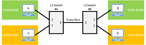
The LAN port settings for #A and #B of this product are as follows.
- Set LAN port #1 as an access port, and associate it with VLAN #1000
- Set LAN port #2 as an access port, and associate it with VLAN #2000
- Set LAN port #3 as a trunk port, and associate it with LAN #1000 and VLAN #2000
- [Switch #A/#B] Define VLAN.
Yamaha(config)#vlan database … (Transition to VLAN mode)
Yamaha(config-vlan)#vlan 1000 … (Define VLAN 1000)
Yamaha(config-vlan)#vlan 2000 … (Define VLAN 2000)
- [Switch #A/#B] Set LAN port #1 as the access port, and associate it with VLAN #1000.
Yamaha(config)#interface port1.1 … (Transition to interface mode)
Yamaha(config-if)#switchport mode access … (Set as access port)
Yamaha(config-if)#switchport access vlan 1000 … (Associate to VLAN 1000)
Yamaha(config-if)#exit
- [Switch #A/#B] Set LAN port #2 as the access port, and associate it with VLAN #2000.
Yamaha(config)#interface port1.2 … (Transition to interface mode)
Yamaha(config-if)#switchport mode access … (Set as access port)
Yamaha(config-if)#switchport access vlan 2000 … (Associate to VLAN 2000)
Yamaha(config-if)#exit
- [Switch #B] Set LAN port #3 as a trunk port, and associate it with VLAN #1000/#2000.
Yamaha(config)#interface port1.3 … (Transition to interface mode)
Yamaha(config-if)#switchport mode trunk … (Set as trunk port)
Yamaha(config-if)#switchport trunk allowed vlan add 1000 … (Add VLAN 1000)
Yamaha(config-if)#switchport trunk allowed vlan add 2000 … (Add VLAN 2000)
Yamaha(config-if)#exit
- Confirm the VLAN settings.
Yamaha#show vlan brief
(u)-Untagged, (t)-Tagged

VLAN ID  Name                            State   Member ports
======= ================================ ======= ======================
1       default                          ACTIVE  port1.3(u)
1000    VLAN1000                         ACTIVE  port1.1(u) port1.3(t)
2000    VLAN2000                         ACTIVE  port1.2(u) port1.3(t)
5.3 Private VLAN settings
This example makes private VLAN settings for this product, to achieve the following.
Hosts connected to ports 1–7 will connect to the Internet and other external lines, through the line to which port 8 is connected
Communications between hosts connected to ports 1–4 are blocked (isolated VLAN: VLAN #21)
Communications between hosts connected to ports 5–7 are permitted (community VLAN: VLAN #22)
Communications between hosts connected to ports 1–4 and ports 5–7 are blocked
Private VLAN setting example
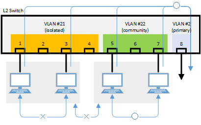
- Define the VLAN ID to be used for the private VLAN.
Yamaha(config)# vlan database … (Transition to VLAN mode)
Yamaha(config-vlan)# vlan 2  … (Create VLAN)
Yamaha(config-vlan)# vlan 21
Yamaha(config-vlan)# vlan 22
Yamaha(config-vlan)# private-vlan 2 primary … (Set Primary VLAN)
Yamaha(config-vlan)# private-vlan 21 isolated … (Set Isolated VLAN)
Yamaha(config-vlan)# private-vlan 22 community … (Set Community VLAN)
Yamaha(config-vlan)# private-vlan 2 association add 21 … (Associate with Primary VLAN)
Yamaha(config-vlan)# private-vlan 2 association add 22
Yamaha(config-vlan)# exit
- Configure the isolated VLAN (VLAN #21) for LAN ports 1–4.
Yamaha(config)#interface port1.1-4 … (Transition to interface mode)
Yamaha(config-if)#switchport mode access … (Set as access port)
Yamaha(config-if)#switchport access vlan 21 .. (Associate to VLAN #21)
Yamaha(config-if)#switchport mode private-vlan host … (Set as private VLAN’s host port)
Yamaha(config-if)#switchport private-vlan host-association 2 add 21
Yamaha(config-if)#exit
- Configure the community VLAN (VLAN #22) for LAN ports 5–7.
Yamaha(config)#interface port1.5-7 … (Transition to interface mode)
Yamaha(config-if)#switchport mode access … (Set as access port)
Yamaha(config-if)#switchport access vlan 22 … (Associate to VLAN #22)
Yamaha(config-if)#switchport mode private-vlan host … (Set as private VLAN’s host port)
Yamaha(config-if)#switchport private-vlan host-association 2 add 22
Yamaha(config-if)#exit
- Configure the primary VLAN (VLAN #2) for LAN port 8. (Promiscuous port)
Yamaha(config)#interface port1.8 … (Transition to interface mode)
Yamaha(config-if)#switchport mode access … (Set as access port)
Yamaha(config-if)#switchport access vlan 2 … (Associate to VLAN #2)
Yamaha(config-if)#switchport mode private-vlan promiscuous … (Set as private VLAN’s promiscuous port)
Yamaha(config-if)#switchport private-vlan mapping 2 add 21
Yamaha(config-if)#switchport private-vlan mapping 2 add 22
Yamaha(config-if)#exit
- Confirm the VLAN settings.
Yamaha#show vlan brief
(u)-Untagged, (t)-Tagged

VLAN ID  Name                            State   Member ports
======= ================================ ======= ======================
1       default                          ACTIVE
2       VLAN0002                         ACTIVE  port1.8(u)
21      VLAN0021                         ACTIVE  port1.1(u) port1.2(u)
                                                 port1.3(u) port1.4(u)
22      VLAN0022                         ACTIVE  port1.5(u) port1.6(u)
                                                 port1.7(u)

Yamaha#show vlan private-vlan
 PRIMARY        SECONDARY          TYPE          INTERFACES
 -------        ---------       ----------      ----------
       2              21          isolated       port1.1 port1.2
                                                 port1.3 port1.4
       2              22         community       port1.5 port1.6
                                                 port1.7
5.4 Voice VLAN settings
Make voice VLAN settings for this product, and implement the following.
Connect an IP phone to port 1. Connect a PC to the other LAN port of the IP phone.
Using LLDP-MED, make the following settings from this product for the IP phone.
- As voice traffic for the IP phone, transmit and receive 802.1q tagged frames of VLAN #2.
- Untagged frames are transmitted and received as PC data traffic.
- Use a CoS value of 6 when transmitting and receiving voice traffic.
- Define the VLAN ID used by the voice VLAN.
Yamaha(config)# vlan database … (transition to vlan mode)
Yamaha(config-vlan)# vlan 2  … (create a VLAN)
Yamaha(config-vlan)# exit
- Set voice VLAN for LAN port #1.
Yamaha(config)#interface port1.1 … (transition to interface mode)
Yamaha(config-if)#switchport mode access … (assign as access port)
Yamaha(config-if)#switchport voice vlan 2 … (set voice traffic as tagged frames of VLAN #2)
Yamaha(config-if)#switchport voice cos 6 … (set CoS value to 6 for voice traffic)
Yamaha(config-if)#exit
- Set QoS for LAN port #1.
Yamaha(config)#qos enable … (enable QoS)
Yamaha(config)#interface port1.1 … (transition to interface mode)
Yamaha(config-if)#qos trust cos ... (set trust mode to CoS)
Yamaha(config-if)#exit
- Set LLDP-MED transmission and reception for LAN port #1.
Yamaha(config)#interface port1.1 … (transition to interface mode)
Yamaha(config-if)#lldp-agent ... (create LLDP agent, transition modes)
Yamaha(lldp-agent)#tlv-select med ... (set LLDP-MED TLV)
Yamaha(lldp-agent)#set lldp enable txrx ... (set LLDP transmission and reception mode)
Yamaha(lldp-agent)#exit
Yamaha(config-if)#exit
Yamaha(config)#lldp run … (enable LLDP function)
Yamaha(config)#exit
6 Points of Caution
A host port that is associated with a private VLAN cannot be aggregated as a link aggregation logical interface; this limitation is specific to host ports.
7 Related Documentation
Multiple VLAN
1 Function Overview
On a multiple VLAN, by associating a port with a multiple VLAN group, you can block traffic from ports that do not belong to the same multiple VLAN group.
You can also join a single port to multiple VLAN groups.
By using this function, it is easy to handle requests to block only traffic between terminals, such as the example below.
Example of using multiple VLANs
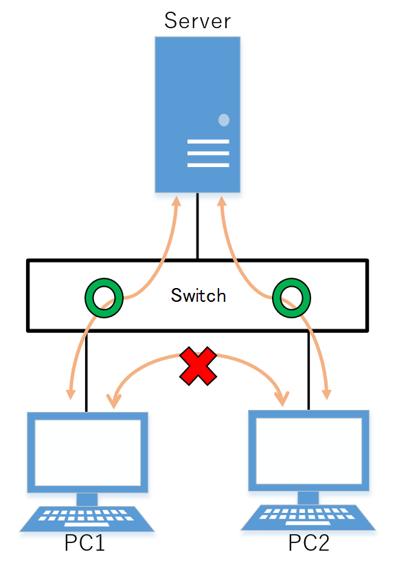
2 Definition of Terms Used
None
3 Function Details
3.1 Operating Specifications
Use the switchport multiple-vlan group command to configure a multiple VLAN group.
Multiple VLANs can be configured as LAN/SFP ports and link aggregation logical interfaces.
If you wish to configure a multiple VLAN group for a trunk port, this will be applied to all relevant VLANs that belong to the port in question.
The VLAN group settings will also be applied to a multicast frame.
This can be used together with the following functions. Control of traffic enable/disable for these functions is set according to the multiple VLAN settings.
- Port-based VLAN/tagged VLAN/voice VLAN
- Port authentication
A multiple VLAN can contain up to 256 groups.
Use the show vlan multiple-vlan group command to confirm the setting status for the interface of each multiple VLAN group.
3.2 Examples of traffic between multiple VLAN groups
Example of traffic for a multiple VLAN group
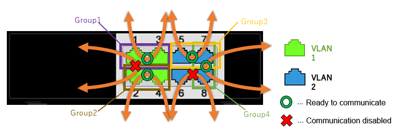
When using multiple VLAN group settings (Group #1 through #4) as shown in the diagram above, enabling/disabling traffic between specific ports A/B and the reasons for such as shown in the table below.
Traffic enabled/disabled between specific ports A/B
| Port number A (group) | Port number B (group) | Traffic enable/disable | Reason |
|---|---|---|---|
| port1.1 (Group 1) | port1.2 (Group 2) | Disabled | The multiple VLAN group is different |
| port1.1 (Group 1) | port1.3 (Group 1) | Enabled | Associated with multiple VLAN group #1 |
| port1.2 (Group 2) | port1.4 (Group 2) | Enabled | Associated with multiple VLAN group #2 |
| port1.5 (Group 3) | port1.7 (Group 3,4) | Enabled | Associated with multiple VLAN group #3 |
| port1.6 (no group) | port1.8 (Group 4) | Disabled | The multiple VLAN group is different |
| port1.7 (Group 3,4) | port1.8 (Group 4) | Enabled | Associated with multiple VLAN group #4 |
Also, traffic can be established between ports that are not associated with a multiple VLAN group, so long as it is within the same VLAN.
3.3 Communication example when inter-VLAN routing is possible
Example of inter-VLAN routing communication
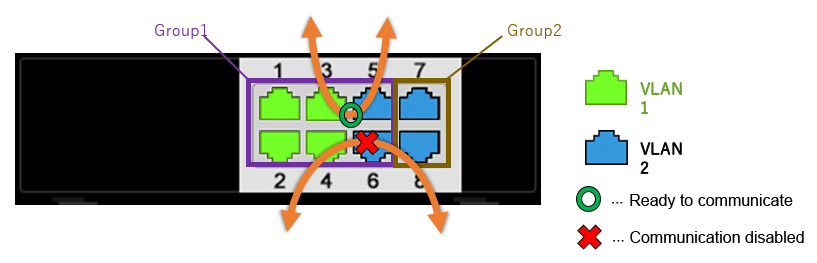
Inter-VLAN routing is possible with L2 switches with routing enabled. In inter-VLAN routing, packets that are routed by hardware can be controlled by multiple VLAN groups.
When using multiple VLAN group settings (Group #1 through #2) as shown in the diagram above, enabling/disabling traffic between specific ports A/B and the reasons for such as shown in the table below.
Communication enable/disable between specific ports A/B when routing between VLANs is possible
| Port number A (group) | Port number B (group) | Traffic enable/disable | Reason |
|---|---|---|---|
| port1.3 (Group 1) | port1.5 (Group 1) | Enabled | Associated with multiple VLAN group #1 |
| port1.4 (Group 1) | port1.8 (Group 2) | Disabled | The multiple VLAN group is different |
4 Related Commands
Related commands are shown below.
For details on the commands, refer to the Command Reference.
List of related commands
| Operations | Operating Commands |
|---|---|
| Multiple VLAN group settings | switchport multiple-vlan group |
| Settings for the name of multiple VLAN group | multiple-vlan group name |
| Sets YMPI frame transmission function when multiple VLANs are specified | multiple-vlan transfer ympi |
| Show multiple VLANs | show vlan multiple-vlan |
5 Examples of Command Execution
5.1 Multiple VLAN settings example 1
This configures multiple VLAN settings to achieve the following.
Hosts connected to ports 1–7 will connect to the Internet and other external lines, through the line to which port 8 is connected
Communications between hosts connected to ports 1–4 are blocked
Communications between hosts connected to ports 5–7 are permitted
Communications between hosts connected to ports 1–4 and ports 5–7 are blocked
Examples of multiple VLAN settings
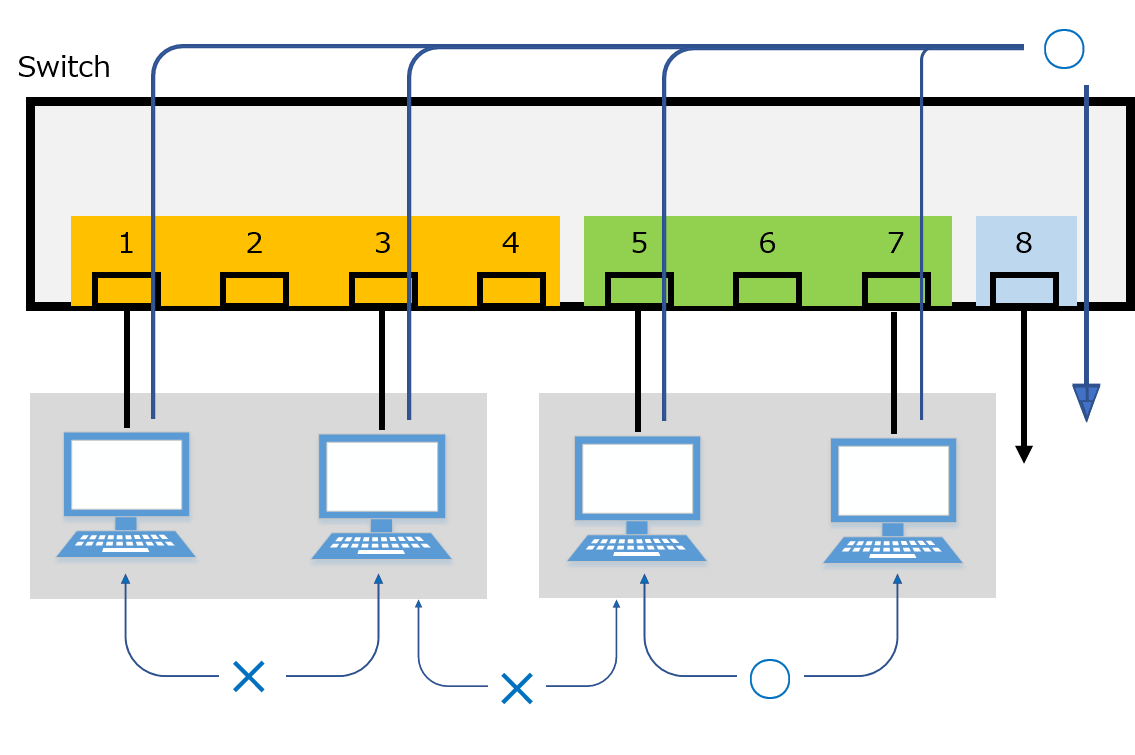
The multiple VLAN group settings are as follows.
- port1.1: Associated with multiple VLAN group #1
- port1.2: Associated with multiple VLAN group #2
- port1.3: Associated with multiple VLAN group #3
- port1.4: Associated with multiple VLAN group #4
- port1.5: Associated with multiple VLAN group #5
- port1.6: Associated with multiple VLAN group #5
- port1.7: Associated with multiple VLAN group #5
- port1.8: Associated with multiple VLAN groups #1, #2, #3, #4, #5
- This sets the name of multiple VLAN group #1 to “Network1”.
Yamaha(config)# multiple-vlan group 1 name Network1 …(settings for the name of multiple VLAN group #1)
- This sets the name of multiple VLAN group #5 to “Network5”.
Yamaha(config)# multiple-vlan group 5 name Network5 …(settings for the name of multiple VLAN group #5)
- Associates port1.1 through port1.4 with multiple VLAN groups #1 through #4 respectively.
Yamaha(config)# interface port1.1 … (Transition to interface mode)
Yamaha(config-if)# switchport multiple-vlan group 1 … (Multiple VLAN group setting)
Yamaha(config-if)# exit
Yamaha(config)# interface port1.2 … (Transition to interface mode)
Yamaha(config-if)# switchport multiple-vlan group 2 … (Multiple VLAN group setting)
Yamaha(config-if)# exit
Yamaha(config)# interface port1.3 … (Transition to interface mode)
Yamaha(config-if)# switchport multiple-vlan group 3 … (Multiple VLAN group setting)
Yamaha(config-if)# exit
Yamaha(config)# interface port1.4 … (Transition to interface mode)
Yamaha(config-if)# switchport multiple-vlan group 4 … (Multiple VLAN group setting)
Yamaha(config-if)# exit
- This associates port1.5 through port1.7 with multiple VLAN group #5.
Yamaha(config)# interface port1.5-7 … (Transition to interface mode)
Yamaha(config-if)# switchport multiple-vlan group 5 … (Multiple VLAN group setting)
Yamaha(config-if)# exit
- This associates port1.8 with multiple VLAN groups #1, #2, #3, #4, #5.
Yamaha(config)# interface port1.8 … (Transition to interface mode)
Yamaha(config-if)# switchport multiple-vlan group 1-5 … (Multiple VLAN group setting)
Yamaha(config-if)# exit
- This checks the multiple VLAN group settings.
Yamaha>show vlan multiple-vlan
GROUP ID  Name                            Member ports
======== ================================ ======================
1        Network1                         port1.1 port1.8
2        GROUP0002                        port1.2 port1.8
3        GROUP0003                        port1.3 port1.8
4        GROUP0004                        port1.4 port1.8
5        Network5                         port1.5 port1.6
                                          port1.7 port1.8
5.2 Multiple VLAN settings example 2
This configures multiple VLAN settings to achieve the following.
Hosts connected to ports 1–7 will connect to the Internet and other external lines, through the line to which port 8 is connected.
Hosts connected to ports 1 to 7 are associated with VLAN #2 and assigned an IP address using DHCP server functionality.
The IP address for VLAN #2 is 192.168.110.240/24 and the range of assigned addresses is from 192.168.110.2 to 192.168.110.191/24.
Communication is blocked between hosts connected to ports 1 to 7.
Examples of multiple VLAN settings
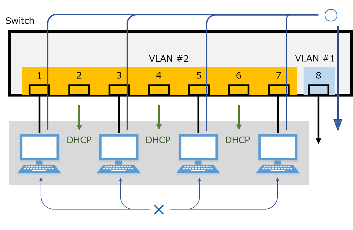
The multiple VLAN group settings are as follows.
- port1.1: Associated with multiple VLAN group #1
- port1.2: Associated with multiple VLAN group #2
- port1.3: Associated with multiple VLAN group #3
- port1.4: Associated with multiple VLAN group #4
- port1.5: Associated with multiple VLAN group #5
- port1.6: Associated with multiple VLAN group #6
- port1.7: Associated with multiple VLAN group #7
- port1.8: Associated with multiple VLAN groups #1, #2, #3, #4, #5, #6, and #7
- Create VLAN #2.
Yamaha(config)# vlan database
Yamaha(config-vlan)# vlan 2 … (Create VLAN !#2)
Yamaha(config-vlan)# exit
Yamaha(config)#
- Assign ports port 1.1 to port 1.7 to VLAN #2.
Yamaha(config)# interface port1.1-7
Yamaha(config-if)# switchport access vlan 2
Yamaha(config-if)#
Yamaha(config)# interface vlan2
Yamaha(config-if)# ip address 192.168.110.240/24
- Create the DHCP pool “pool_vlan2”.
Yamaha(config)# dhcp pool pool_vlan2
Yamaha(config-dhcp)# … (Switch to DHCP mode)
- Specify the VLAN #2 network portion 192.168.110.0/24 in the DHCP pool.
Yamaha(config-dhcp)# network 192.168.110.0/24
- Specify the address assignment range from 192.168.110.2 to 192.168.110.191 in the DHCP pool.
Yamaha(config-dhcp)# range 192.168.110.2 192.168.110.191
- Specify the default gateway to be notified in DHCP option settings and specify the DNS server in the DHCP pool.
Yamaha(config-dhcp)# default-router 192.168.110.240 … (Default gateway address is 192.168.110.240 (itself))
Yamaha(config-dhcp)# dns-server 192.168.110.1 … (DNS server address is 192.168.110.1)
Yamaha(config-dhcp)# exit … (End DHCP mode)
- Activate the DHCP server function using vlan2.
Yamaha(config)# interface vlan2 … (Switch to interface mode)
Yamaha(config-if)# dhcp-server enable ... (Enable DHCP server function for the interface)
Yamaha(config-if)# exit ... (End interface mode)
- Activate the DHCP server function for the entire system.
Yamaha(config)# dhcp-server enable ... (Enable DHCP server functionality for entire system)
- Associates port 1.1 through port 1.7 with multiple VLAN groups #1 through #7 respectively.
Yamaha(config)# interface port1.1 … (Switch to interface mode)
Yamaha(config-if)# switchport multiple-vlan group 1 … (Set multiple VLAN group setting)
Yamaha(config-if)# exit
Yamaha(config)# interface port1.2 … (Switch to interface mode)
Yamaha(config-if)# switchport multiple-vlan group 2 … (Set multiple VLAN group setting)
Yamaha(config-if)# exit
Yamaha(config)# interface port1.3 … (Switch to interface mode)
Yamaha(config-if)# switchport multiple-vlan group 3 … (Set multiple VLAN group setting)
Yamaha(config-if)# exit
Yamaha(config)# interface port1.4 … (Switch to interface mode)
Yamaha(config-if)# switchport multiple-vlan group 4 … (Set multiple VLAN group setting)
Yamaha(config-if)# exit
Yamaha(config)# interface port1.5 … (Switch to interface mode)
Yamaha(config-if)# switchport multiple-vlan group 5 … (Set multiple VLAN group setting)
Yamaha(config-if)# exit
Yamaha(config)# interface port1.6 … (Switch to interface mode)
Yamaha(config-if)# switchport multiple-vlan group 6 … (Set multiple VLAN group setting)
Yamaha(config-if)# exit
Yamaha(config)# interface port1.7 … (Switch to interface mode)
Yamaha(config-if)# switchport multiple-vlan group 7 … (Set multiple VLAN group setting)
Yamaha(config-if)# exit
- Associate port 1.8 with multiple VLAN groups #1 to #7.
Yamaha(config)# interface port1.8 … (Switch to interface mode)
Yamaha(config-if)# switchport multiple-vlan group 1-7 … (Specify multiple VLAN group setting)
Yamaha(config-if)# exit
- This checks the multiple VLAN group settings.
Yamaha>show vlan multiple-vlan
GROUP ID  Name                            Member ports
======== ================================ ======================
1        GROUP0001                        port1.1 port1.8
2        GROUP0002                        port1.2 port1.8
3        GROUP0003                        port1.3 port1.8
4        GROUP0004                        port1.4 port1.8
5        GROUP0005                        port1.5 port1.8
6        GROUP0006                        port1.6 port1.8
7        GROUP0007                        port1.7 port1.8
6 Points of Caution
The points of caution regarding this function are as follows.
- The function cannot be used in conjunction with a private VLAN.
- The multiple VLAN group to associate with a link aggregation logical interface must be the same.
- A multiple VLAN group is only applicable to forwarding between ports. Voluntary packets will not be affected by the settings of a multiple VLAN group.
- Even if a multiple VLAN is configured, communication may not work correctly due to the following influences.
- Block status of spanning tree
- IGMP snooping/MLD snooping status
- Blocked status of loop detection
- In inter-VLAN routing, multiple VLAN communication restrictions are applied only to packets routed by hardware processing.
Restrictions do not apply to inter-VLAN routing through the CPU.
YMPI frames are transmitted for managing Yamaha wireless access points if multiple VLANs are specified.
Therefore, even if there are multiple Yamaha wireless access points associated with different VLAN groups, cluster management functionality or wireless LAN controller functionality can be used.
7 Related Documentation
Spanning tree
1 Function Overview
The spanning tree is a function that maintains redundancies in the network routes while preventing loops.
Normally, the L2 switch floods the adjacent switch with the broadcast packets.
If the network is constructed as a loop, the switches will flood each other, causing the loop to occur.
This results in a major degradation of bandwidth and CPU resources in the switches.
The spanning tree determines the roles of each port and establishes a network construction where the broadcast packets do not keep traveling around, for networks that contain physical loops as well.
When there are problems linking, the problem is detected and the tree is reconstructed in order to restore the system.
This product supports STP, RSTP, and MSTP.
Spanning tree function overview
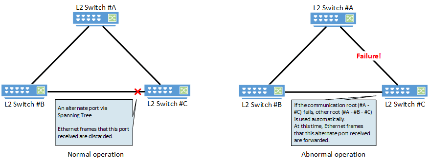
2 Definition of Terms Used
- STP: Spanning Tree Protocol (802.1d)
The spanning tree protocol (STP) exchanges BPDU (bridge protocol data unit) messages, in order to avoid loops.
This product supports IEEE802.1d and RFC4188.
- RSTP: Rapid Spanning Tree Protocol (802.1w)
The rapid spanning tree protocol (RSTP) is an extension of STP. It can recover the spanning tree more quickly than STP, when the network architecture has changed or when there is a problem linking.
This product supports IEEE802.1w and RFC4318.
- MSTP: Multiple Spanning Tree Protocol (802.1s)
Multiple spanning tree protocol (MSTP) is a further extension of STP and RSTP. It groups the VLAN into instances, and constructs a spanning tree for each group.
This can be used to distribute load within the network routes.
This product supports IEEE802.1s.
3 Function Details
This product supports the following functions in order to flexibly handle the construction of routes based on MSTP.
- Set priority
- Set bridge priority
- Set port priority
- Set path cost
- Set timeout
- Set forward delay time
- Set maximum aging time
- Specify edge port (Port Fast settings)
- BPDU guard
- BPDU filtering
- Route guard
4 Related Commands
The related commands are shown below.
For details on the commands, refer to the Command Reference.
List of related commands
| Operations | Operating Commands |
|---|---|
| Set spanning tree for the system | spanning-tree shutdown |
| Set forward delay time | spanning-tree forward-time |
| Set maximum aging time | spanning-tree max-age |
| Set bridge priority | spanning-tree priority |
| Set spanning tree for an interface | spanning-tree |
| Set spanning tree link type | spanning-tree link-type |
| Set interface BPDU filtering | spanning-tree bpdu-filter |
| Set interface BPDU guard | spanning-tree bpdu-guard |
| Set interface path cost | spanning-tree path-cost |
| Set interface priority | spanning-tree priority |
| Set edge port for interface | spanning-tree edgeport |
| Show spanning tree status | show spanning-tree |
| Show spanning tree BPDU statistics | show spanning-tree statistics |
| Clear protocol compatibility mode | clear spanning-tree detected protocols |
| Move to MST mode | spanning-tree mst configuration |
| Generate MST instance | instance |
| Set VLAN for MST instance | instance vlan |
| Set priority of MST instance | instance priority |
| Set MST region name | region |
| Set revision number of MST region | revision |
| Set MST instance for interface | spanning-tree instance |
| Set interface priority for MST instance | spanning-tree instance priority |
| Set interface path cost for MST instance | spanning-tree instance path-cost |
| Show MST region information | show spanning-tree mst config |
| Show MSTP information | show spanning-tree mst |
| Show MST instance information | show spanning-tree mst instance |
5 Examples of Command Execution
5.1 MSTP setting example
Use this product to realize the architecture shown in the diagram below.
MSTP architecture diagram
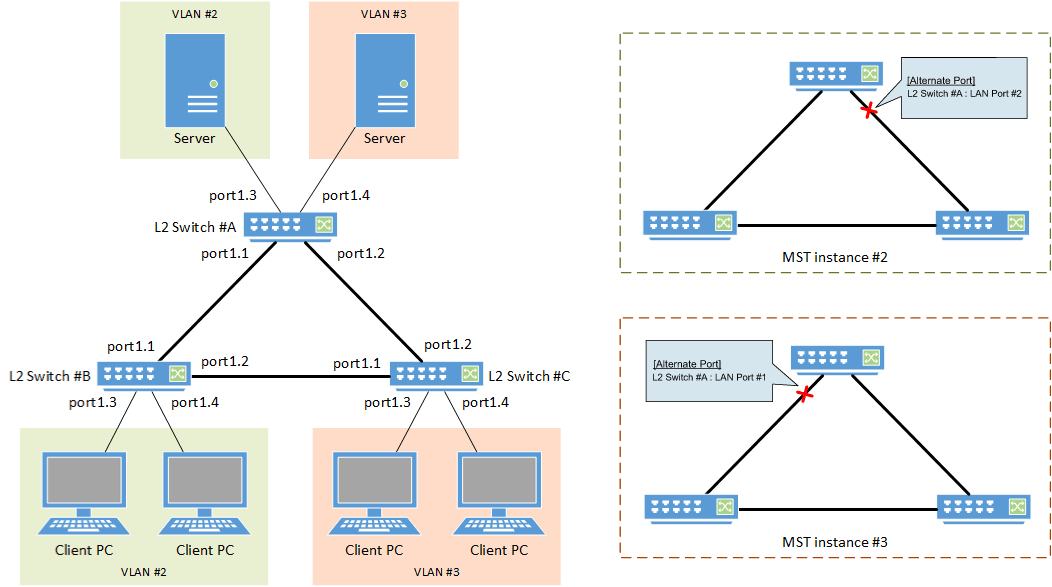
- In this example, MST instances are used to construct the spanning tree.
- A different route is set for each MST instance (VLAN), in order to distribute network load.
- The LAN port that is connected to the PC is set as the edge port.
- [Switch #A] Define VLAN #2 and VLAN #3.
Yamaha(config)#vlan database
Yamaha(config-vlan)#vlan 2                              ... (VLAN #2 definition)
Yamaha(config-vlan)#vlan 3                              ... (VLAN #3 definition)
Yamaha(config-vlan)#exit
- [Switch #A] Set the CIST priority.
Yamaha(config)#spanning-tree priority 8192 ... (Set CIST priority to 8192)
- [Switch #A] Set the MST.
Yamaha(config)#spanning-tree mst configuration
Yamaha(config-mst)#region Sample                        ... (Set MST region name to “Sample”)
Yamaha(config-mst)#revision 1                           ... (Set MST revision number to 1)
Yamaha(config-mst)#instance 2 vlan 2                    ... (Define MST interface #2, and associate with VLAN #2)
Yamaha(config-mst)#instance 3 vlan 3                    ... (Define MST interface #3, and associate with VLAN #3)
Yamaha(config-mst)#exit
- [Switch #A] Set LAN ports #1–#2 as trunk ports, and associate them with VLAN #2–#3.
Also, set the MST instances #2–#3.
Yamaha(config)#interface port1.1
Yamaha(config-if)#switchport mode trunk                 ... (Set as trunk port)
Yamaha(config-if)#switchport trunk allowed vlan add 2,3 ... (Associate to VLAN #2–#3)
Yamaha(config-if)#spanning-tree instance 2              ... (Set MST instance #2)
Yamaha(config-if)#spanning-tree instance 3              ... (Set MST instance #3)
Yamaha(config-if)#exit
(Also perform the above settings for LAN port #2.)
- [Switch #A] Set LAN port #3 as the access port, and associate it with VLAN #2.
Also, set the MST instance #2, and make it an edge port.
Yamaha(config)#interface port1.3
Yamaha(config-if)#switchport mode access                ... (Set as access port)
Yamaha(config-if)#switchport access vlan 2              ... (Associate to VLAN #2)
Yamaha(config-if)#spanning-tree instance 2              ... (Set MST instance #2)
Yamaha(config-if)#spanning-tree edgeport                ... (Set as edge port)
Yamaha(config-if)#exit
- [Switch #A] Set LAN port #4 as the access port, and associate it with VLAN #3.
Also, set the MST instance #3, and make it an edge port.
Yamaha(config)#interface port1.4
Yamaha(config-if)#switchport mode access                ... (Set as access port)
Yamaha(config-if)#switchport access vlan 3              ... (Associate to VLAN #3)
Yamaha(config-if)#spanning-tree instance 3              ... (Set MST instance #3)
Yamaha(config-if)#spanning-tree edgeport                ... (Set as edge port)
Yamaha(config-if)#exit
- [Switch #B] Define VLAN #2 and VLAN #3.
Yamaha(config)#vlan database
Yamaha(config-vlan)#vlan 2                              ... (VLAN #2 definition)
Yamaha(config-vlan)#vlan 3                              ... (VLAN #3 definition)
Yamaha(config-vlan)#exit
- [Switch #B] Set the CIST priority.
Yamaha(config)#spanning-tree priority 16384 ... (Set CIST priority to 16384)
- [Switch #B] Set the MST.
Yamaha(config)#spanning-tree mst configuration
Yamaha(config-mst)#region Sample                        ... (Set MST region name to “Sample”)
Yamaha(config-mst)#revision 1                           ... (Set MST revision number to 1)
Yamaha(config-mst)#instance 2 vlan 2                    ... (Define MST interface #2, and associate with VLAN #2)
Yamaha(config-mst)#instance 2 priority 8192             ... (Set priority of MST instance #2 to 8192)
Yamaha(config-mst)#instance 3 vlan 3                    ... (Define MST interface #3, and associate with VLAN #3)
Yamaha(config-mst)#instance 3 priority 16384            ... (Set priority of MST instance #3 to 16384)
Yamaha(config-mst)#exit
- [Switch #B] Set LAN ports #1–#2 as trunk ports, and associate them with VLAN #2–#3.
Also, set the MST instances #2–#3.
Yamaha(config)#interface port1.1
Yamaha(config-if)#switchport mode trunk                 ... (Set as trunk port)
Yamaha(config-if)#switchport trunk allowed vlan add 2,3 ... (Associate to VLAN #2–#3)
Yamaha(config-if)#spanning-tree instance 2              ... (Set MST instance #2)
Yamaha(config-if)#spanning-tree instance 3              ... (Set MST instance #3)
Yamaha(config-if)#exit
(Also perform the above settings for LAN port #2.)
- [Switch #B] Set LAN port #3 as the access port, and associate it with VLAN #2.
Also, set the MST instance #2, and make it an edge port.
Yamaha(config)#interface port1.3
Yamaha(config-if)#switchport mode access                ... (Set as access port)
Yamaha(config-if)#switchport access vlan 2              ... (Associate to VLAN #2)
Yamaha(config-if)#spanning-tree instance 2              ... (Set MST instance #2)
Yamaha(config-if)#spanning-tree edgeport                ... (Set as edge port)
Yamaha(config-if)#exit
(Also perform the above settings for LAN port #4.)
- [Switch #C] Define VLAN #2 and VLAN #3.
Yamaha(config)#vlan database
Yamaha(config-vlan)#vlan 2                              ... (VLAN #2 definition)
Yamaha(config-vlan)#vlan 3                              ... (VLAN #3 definition)
Yamaha(config-vlan)#exit
- [Switch #C] Set the MST.
Yamaha(config)#spanning-tree mst configuration
Yamaha(config-mst)#region Sample                        ... (Set MST region name to “Sample”)
Yamaha(config-mst)#revision 1                           ... (Set MST revision number to 1)
Yamaha(config-mst)#instance 2 vlan 2                    ... (Define MST interface #2, and associate with VLAN #2)
Yamaha(config-mst)#instance 2 priority 16384            ... (Set priority of MST instance #2 to 16384)
Yamaha(config-mst)#instance 3 vlan 3                    ... (Define MST interface #3, and associate with VLAN #3)
Yamaha(config-mst)#instance 3 priority 8192             ... (Set priority of MST instance #3 to 8192)
Yamaha(config-mst)#exit
- [Switch #C] Set LAN ports #1–#2 as trunk ports, and associate them with VLAN #2–#3.
Also, set the MST instances #2–#3.
Yamaha(config)#interface port1.1
Yamaha(config-if)#switchport mode trunk                 ... (Set as trunk port)
Yamaha(config-if)#switchport trunk allowed vlan add 2,3 ... (Associate to VLAN #2–#3)
Yamaha(config-if)#spanning-tree instance 2              ... (Set MST instance #2)
Yamaha(config-if)#spanning-tree instance 3              ... (Set MST instance #3)
Yamaha(config-if)#exit
(Also perform the above settings for LAN port #2.)
- [Switch #C] Set LAN port #3 as the access port, and associate it with VLAN #3.
Also, set the MST instance #3, and make it an edge port.
Yamaha(config)#interface port1.3
Yamaha(config-if)#switchport mode access                ... (Set as access port)
Yamaha(config-if)#switchport access vlan 3              ... (Associate to VLAN #3)
Yamaha(config-if)#spanning-tree instance 3              ... (Set MST instance #3)
Yamaha(config-if)#spanning-tree edgeport                ... (Set as edge port)
Yamaha(config-if)#exit
(Also perform the above settings for LAN port #4.)
- Connect the LAN cable.
- [Switch #A] Check the CIST architecture.
Yamaha>show spanning-tree | include Root Id
% Default: CIST Root Id 200100a0deaeb920      ... (The higher-priority switch #A is the CIST root bridge)
% Default: CIST Reg Root Id 200100a0deaeb920

Yamaha>show spanning-tree | include Role
%   port1.1: Port Number 905 - Ifindex 5001 - Port Id 0x8389 - Role Designated - State Forwarding
%   port1.2: Port Number 906 - Ifindex 5002 - Port Id 0x838a - Role Designated - State Forwarding
%   port1.3: Port Number 907 - Ifindex 5003 - Port Id 0x838b - Role Designated - State Forwarding
%   port1.4: Port Number 908 - Ifindex 5004 - Port Id 0x838c - Role Designated - State Forwarding
%   port1.5: Port Number 909 - Ifindex 5005 - Port Id 0x838d - Role Disabled - State Discarding
%   port1.6: Port Number 910 - Ifindex 5006 - Port Id 0x838e - Role Disabled - State Discarding
%   port1.7: Port Number 911 - Ifindex 5007 - Port Id 0x838f - Role Disabled - State Discarding
%   port1.8: Port Number 912 - Ifindex 5008 - Port Id 0x8390 - Role Disabled - State Discarding
%   port1.9: Port Number 913 - Ifindex 5009 - Port Id 0x8391 - Role Disabled - State Discarding
%   port1.10: Port Number 914 - Ifindex 5010 - Port Id 0x8392 - Role Disabled - State Discarding
- [Switch #B] Check the CIST architecture.
Yamaha>show spanning-tree | include Root Id
% Default: CIST Root Id 200100a0deaeb920      ... (The higher-priority switch #A is the CIST root bridge)
% Default: CIST Reg Root Id 200100a0deaeb920

Yamaha>show spanning-tree | include Role
%   port1.1: Port Number 905 - Ifindex 5001 - Port Id 0x8389 - Role Rootport - State Forwarding
%   port1.2: Port Number 906 - Ifindex 5002 - Port Id 0x838a - Role Designated - State Forwarding
%   port1.3: Port Number 907 - Ifindex 5003 - Port Id 0x838b - Role Designated - State Forwarding
%   port1.4: Port Number 908 - Ifindex 5004 - Port Id 0x838c - Role Designated - State Forwarding
%   port1.5: Port Number 909 - Ifindex 5005 - Port Id 0x838d - Role Disabled - State Discarding
%   port1.6: Port Number 910 - Ifindex 5006 - Port Id 0x838e - Role Disabled - State Discarding
%   port1.7: Port Number 911 - Ifindex 5007 - Port Id 0x838f - Role Disabled - State Discarding
%   port1.8: Port Number 912 - Ifindex 5008 - Port Id 0x8390 - Role Disabled - State Discarding
%   port1.9: Port Number 913 - Ifindex 5009 - Port Id 0x8391 - Role Disabled - State Discarding
%   port1.10: Port Number 914 - Ifindex 5010 - Port Id 0x8392 - Role Disabled - State Discarding
- [Switch #C] Check the CIST architecture.
Yamaha>show spanning-tree | include Root Id
% Default: CIST Root Id 200100a0deaeb920      ... (The higher-priority switch #A is the CIST root bridge)
% Default: CIST Reg Root Id 200100a0deaeb920

Yamaha>show spanning-tree | include Role
%   port1.1: Port Number 905 - Ifindex 5001 - Port Id 0x8389 - Role Alternate - State Discarding ... (LAN #1 port of lower-priority switch #C is the CIST alternate port)
%   port1.2: Port Number 906 - Ifindex 5002 - Port Id 0x838a - Role Rootport - State Forwarding
%   port1.3: Port Number 907 - Ifindex 5003 - Port Id 0x838b - Role Designated - State Forwarding
%   port1.4: Port Number 908 - Ifindex 5004 - Port Id 0x838c - Role Designated - State Forwarding
%   port1.5: Port Number 909 - Ifindex 5005 - Port Id 0x838d - Role Disabled - State Discarding
%   port1.6: Port Number 910 - Ifindex 5006 - Port Id 0x838e - Role Disabled - State Discarding
%   port1.7: Port Number 911 - Ifindex 5007 - Port Id 0x838f - Role Disabled - State Discarding
%   port1.8: Port Number 912 - Ifindex 5008 - Port Id 0x8390 - Role Disabled - State Discarding
%   port1.9: Port Number 913 - Ifindex 5009 - Port Id 0x8391 - Role Disabled - State Discarding
%   port1.10: Port Number 914 - Ifindex 5010 - Port Id 0x8392 - Role Disabled - State Discarding
- [Switch #A] Check the architecture of MST instance #2.
Yamaha>show spanning-tree mst instance 2 | include Root Id
% Default: MSTI Root Id 200200a0deaeb879      ... (The higher-priority switch #B is the root bridge for MST instance #2)

Yamaha>show spanning-tree mst instance 2 | include Role
%   port1.1: Port Number 905 - Ifindex 5001 - Port Id 0x8389 - Role Rootport - State Forwarding
%   port1.2: Port Number 906 - Ifindex 5002 - Port Id 0x838a - Role Alternate - State Discarding ... (LAN #2 port of lower-priority switch #A is the alternate port for MST instance #2)
%   port1.3: Port Number 907 - Ifindex 5003 - Port Id 0x838b - Role Designated - State Forwarding
- [Switch #B] Check the architecture of MST instance #2.
Yamaha>show spanning-tree mst instance 2 | include Root Id % Default: MSTI Root Id 200200a0deaeb879 ... (The higher-priority switch #B is the root bridge for MST instance #2) Yamaha>show spanning-tree mst instance 2 | include Role % port1.1: Port Number 905 - Ifindex 5001 - Port Id 0x8389 - Role Designated - State Forwarding % port1.2: Port Number 906 - Ifindex 5002 - Port Id 0x838a - Role Designated - State Forwarding % port1.3: Port Number 907 - Ifindex 5003 - Port Id 0x838b - Role Designated - State Forwarding % port1.4: Port Number 908 - Ifindex 5004 - Port Id 0x838c - Role Designated - State Forwarding
- [Switch #C] Check the architecture of MST instance #2.
Yamaha>show spanning-tree mst instance 2 | include Root Id % Default: MSTI Root Id 200200a0deaeb879 ... (The higher-priority switch #B is the root bridge for MST instance #2) Yamaha>show spanning-tree mst instance 2 | include Role % port1.1: Port Number 905 - Ifindex 5001 - Port Id 0x8389 - Role Rootport - State Forwarding % port1.2: Port Number 906 - Ifindex 5002 - Port Id 0x838a - Role Designated - State Forwarding
- [Switch #A] Check the architecture of MST instance #3.
Yamaha>show spanning-tree mst instance 3 | include Root Id % Default: MSTI Root Id 200300a0deaeb83d ... (The higher-priority switch #C is the root bridge for MST instance #3) Yamaha>show spanning-tree mst instance 3 | include Role % port1.1: Port Number 905 - Ifindex 5001 - Port Id 0x8389 - Role Alternate - State Discarding ... (LAN #1 port of lower-priority switch #A is the alternate port for MST instance #3) % port1.2: Port Number 906 - Ifindex 5002 - Port Id 0x838a - Role Rootport - State Forwarding % port1.4: Port Number 908 - Ifindex 5004 - Port Id 0x838c - Role Designated - State Forwarding
- [Switch #B] Check the architecture of MST instance #3.
Yamaha>show spanning-tree mst instance 3 | include Root Id % Default: MSTI Root Id 200300a0deaeb83d ... (The higher-priority switch #C is the root bridge for MST instance #3) Yamaha>show spanning-tree mst instance 3 | include Role % port1.1: Port Number 905 - Ifindex 5001 - Port Id 0x8389 - Role Designated - State Forwarding % port1.2: Port Number 906 - Ifindex 5002 - Port Id 0x838a - Role Rootport - State Forwarding
- [Switch #C] Check the architecture of MST instance #3.
Yamaha>show spanning-tree mst instance 3 | include Root Id % Default: MSTI Root Id 200300a0deaeb83d ... (The higher-priority switch #C is the root bridge for MST instance #3) Yamaha>show spanning-tree mst instance 3 | include Role % port1.1: Port Number 905 - Ifindex 5001 - Port Id 0x8389 - Role Designated - State Forwarding % port1.2: Port Number 906 - Ifindex 5002 - Port Id 0x838a - Role Designated - State Forwarding % port1.3: Port Number 907 - Ifindex 5003 - Port Id 0x838b - Role Designated - State Forwarding % port1.4: Port Number 908 - Ifindex 5004 - Port Id 0x838c - Role Designated - State Forwarding
6 Points of Caution
- STP and RSTP on this product are supported by backward-compatibility provided by MSTP.
7 Related Documentation
- L2 switching functions: VLAN
- STP
- IEEE802.1d
- RFC4188
- RSTP
- IEEE802.1w
- RFC4318
- MSTP
- IEEE802.1s
- SWX3220 Series Technical Data (Basic Functions)
- Layer 2 functions
- Proprietary loop detection
Proprietary loop detection
1 Function Overview
This product offers a proprietary system to detect whether there is a loop in the network environment that was configured.
A proprietary loop detection frame is sent from the LAN/SFP port, and the unit monitors whether the frame returns or not.
If the transmitted frame returns, the system determines that there is a loop in the port in question.
2 Definition of Terms Used
- LDF (Loop Detection Frame)
- This is a Yamaha proprietary Ethernet frame that is used to detect loops.
3 Function Details
3.1 Loop detection operating specifications
The loop detection specifications for this product are shown below.
- In addition to enabling/disabling the entire system, the loop detection on this product can enable/disable individual ports.
When detecting loops in LAN/SFP ports, the system-wide setting must be set to enable.
- Use the loop-detect command in global configuration mode for system-wide settings.
- Use the loop-detect command in the interface mode of the relevant port for individual LAN/SFP port settings.
- The default settings for the loop detection function are as shown below. (In the initial state, this function is not operating.)
- System-wide settings: disabled
- LAN/SFP port settings: enabled
- When the system-wide settings for both loop detection and spanning tree protocol are set to enabled, the spanning tree protocol is given priority for LAN/SFP port settings.
- If the loop detection function is enabled for this product, the following operations are performed.
- Loop detection frames (hereafter “LDF”) are sent every two seconds from the linked-up LAN/SFP port.
The loop detection function cannot be used on static/LACP logical interfaces, and ports on which mirror settings have been made (mirror ports).
- When the transmitted loop detection frame receives itself, it determines that a loop has occurred, and the following operations are performed.
- Port Shutdown
When both the transmitting and the receiving LAN/SFP port is the same, the relevant port is shut down.
The linkup will be made five minutes after shutdown, and LDF transmission will resume. (If a loop has occurred, this operation will repeat.)
When a linkup to the relevant port is desired within five minutes of monitored time, the no shutdown command is used.
- Port Blocking
When the port number of the transmitting LAN/SFP port is smaller than the receiving port number, all frames except for LDF are blocked.
The LDF will be transmitted periodically, but LDF will not be forwarded from other devices.
For the LAN/SFP ports that were blocked, if the LDF that was transmitted does not return within five seconds, it is determined that the loop has been resolved, and normal communications are resumed.
- Port Detected
When the port number of the LAN/SFP port that was transmitted is larger than the port number during reception, another port is doing the blocking, so communication continues as normal.
- Port Shutdown
- When a loop is detected, the port lamp display on this product changes to a dedicated status, and the following SYSLOG message is output.
- [LOOP]: inf: Detected Loop!: port1.1, 1.3 … (displayed in a five-second cycle, starting from the detection of the loop)
- The port lamp display on this product is restored as communications are resumed after the loop is resolved, and the following SYSLOG message is output.
- [LOOP]: inf: Recovered Loop! : port1.1, 1.3
- Loop detection frames (hereafter “LDF”) are sent every two seconds from the linked-up LAN/SFP port.
- The “detected” operation can be forcibly performed without performing shutdown/blocking of the LAN/SFP port on which the loop was detected.
- Use the loop-detect blocking-disable command for this setting.
- If this setting is “enabled”, port blocking will be implemented on the next largest port number. (Shutdown operations will not occur.)
- A force-clear can be performed on the loop detection status (detected, blocking) by using the loop-detect reset command. (On models equipped with a [MODE] button, this can be also done by holding down the [MODE] button for three seconds.)
If a linkdown has occurred on the port where a loop has been detected, the detection status will be cleared. (The port lamp display is restored, and the following syslog message is outputted.)
- The status of the loop detection function can be checked using the show loop-detect command. The following is displayed.
- System Enable/disable status
- Loop detection status (status for each LAN/SFP port)
- When an LDF is received by a LAN/SFP port when the loop detection function is disabled, the received frames from all other ports will be forwarded as-is.
However, frames will not be forwarded for static/LACP logical interfaces and ports on which mirror settings have been made (mirror ports).
- In the following kinds of situations, loops in hubs that are connected to this product might not be detected.
- Loops are being detected in a connected hub
- Loop detection frames are not being forwarded by a connected hub
3.2 Loop detection example
The following shows examples of loop detection in this product.
Loop detection example
| Loop detection case | Configuration example | Loop detection status |
|---|---|---|
| 1 |  | A loop is detected when the device receives the LDF that it has transmitted.
|
| 2 |  | When loops are detected in multiple ports on the same terminal, the port with the largest number is blocked.
|
| 3 | 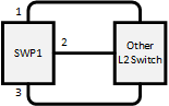 | The loop is avoided by blocking multiple ports. The blocking port is selected using the same rules as case 2.
|
| 4 | 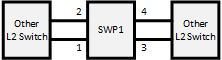 | When loops are detected in multiple groups, the port with the largest number in each group is blocked.
|
| 5 | 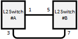 | When a loop occurs between two switches, one of the switches detects the loop. ○When detected in port1.3 of switch #A
○When detected in port1.7 of switch #B
|
| 6 | 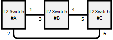 | Out of the six ports that are connected by cable, the port for which the loop is most quickly detected is the one that is blocked. ○When detected in port1.2 of switch #A
○When detected in port1.4 of switch #B
○When detected in port1.6 of switch #C
|
| 7 | 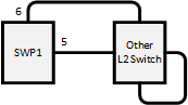 | Because the LDF transmitted from each port returns to these ports, port1.5 and port1.6 will both shut down.
|
| 8 | 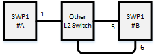 | Port1.6 of switch #B is blocked. Depending on the timing, port1.1 of switch #A will shut down; but the loop in port1.1 of switch #A is resolved by blocking port1.6 of switch #B.
|
4 Related Commands
The related commands are shown below.
For details on the commands, refer to the Command Reference.
List of related commands
| Operations | Operating Commands |
|---|---|
| Enable/disable loop detection function (system) | loop-detect enable/disable |
| Enable/disable loop detection function (LAN/SFP port) | loop-detect enable/disable |
| Set port blocking for loop detection | loop-detect blocking enable/disable |
| Set port blocking connection time when a loop is detected | loop-detect blocking interval |
| Reset loop detection status | loop-detect reset |
| Refer to the setting status of loop detection | show loop-detect |
5 Examples of Command Execution
This example detects any loops occurring on this product using the following configuration, when the loop detection function is enabled.
- [Example 1] Loop occurring within this product
- [Example 2] Loop occurring in a third-party hub connected to this product
- This sets LAN ports #1 and #3 to detect loops.
- Enable the loop detection function for the entire system.
Yamaha(config)#loop-detect enable ... (Enable the system-wide loop detection function)
- Enable the loop detection function for LAN ports #1 and #3.
Yamaha(config)#interface port1.1 Yamaha(config-if)#spanning-tree disable ... (Disable the spanning tree function for each LAN port) Yamaha(config-if)#loop-detect enable ... (Enable the loop detection function for each LAN port) Yamaha(config-if)#loop-detect blocking enable ... (Enable blocking) (Also perform the above settings for LAN port #3.)
- The loop detection function for each LAN port and blocking are both enabled by default, so there is no need to set them.
- Confirm that the loop detection function has been set.
Confirm whether the loop detection function is enabled(*) for LAN ports #1 and #3.
Yamaha>show loop-detect loop-detect: Enable port loop-detect port-blocking status ------------------------------------------------------- port1.1 enable(*) enable Normal port1.2 enable enable Normal port1.3 enable(*) enable Normal port1.4 enable enable Normal port1.5 enable enable Normal port1.6 enable enable Normal port1.7 enable enable Normal port1.8 enable enable Normal port1.9 enable enable Normal : : : : ------------------------------------------------------- (*): Indicates that the feature is enabled.
- If a loop has been detected, the loop detection status can be checked.
- In the case of example 1:
Yamaha>show loop-detect loop-detect: Enable port loop-detect port-blocking status ------------------------------------------------------- port1.1 enable(*) enable Detected ... (LAN port #1 changes to the Detected state) port1.2 enable enable Normal port1.3 enable(*) enable Blocking ... (LAN port #3 changes to the Blocking state) port1.4 enable enable Normal port1.5 enable enable Normal port1.6 enable enable Normal port1.7 enable enable Normal port1.8 enable enable Normal port1.9 enable enable Normal : : : : ------------------------------------------------------- (*): Indicates that the feature is enabled.
- In the case of example 2:
Yamaha>show loop-detect loop-detect: Enable port loop-detect port-blocking status ------------------------------------------------------- port1.1 enable(*) enable Shutdown ... (LAN port #1 changes to the Shutdown state) port1.2 enable enable Normal port1.3 enable(*) enable Normal port1.4 enable enable Normal port1.5 enable enable Normal port1.6 enable enable Normal port1.7 enable enable Normal port1.8 enable enable Normal port1.9 enable enable Normal : : : : ------------------------------------------------------- (*): Indicates that the feature is enabled.
- In the case of example 1:
6 Points of Caution
None
7 Related Documentation
- SWX3220 Series Technical Data (Basic Functions)
- Layer 3 functions
- IPv4/IPv6 common settings
IPv4/IPv6 common settings
1 Function Overview
This product is compatible with the following network environment settings that are common to IPv4 and IPv6, mainly for the purpose of maintenance (configuring the settings of the switch).
- DNS client settings
- Equal cost multipath settings
2 Definition of Terms Used
None
3 Function Details
3.1 DNS client settings
This product supports DNS (Domain Name System) clients.
If a FQDN (Fully Qualified Domain Name) has been set for an NTP server or a syslog server, an inquiry is made to the DNS server to retrieve the IPv4/IPv6 address.
This product provides the following DNS client control functions.
- Set IP address of the DNS server
- Set default domain name
- Set query domain list
Inquiries to the DNS server are enabled by default, and the setting can be changed by using the dns-client enable/disable command.
3.1.1 Set IP address of the DNS server
Up to three IP addresses can be set for the DNS server, using the methods shown below.
- Manual setting using the dns-client name-server command
- This lets you specify the IPv4/IPv6 address.
- Automatic setting via DHCP
- The highest default gateway value takes priority if there is more than one.
This product always gives priority to the information that was set via commands.
Check the configured DNS servers by using the show dns-client command.
3.1.2 Set default domain
Only one default domain can be set using the methods shown below. The domain can be specified using up to 256 characters.
- Manual setting using the dns-client domain-name command
- Automatic setting via DHCP
- The highest default gateway value takes priority if there is more than one.
As with the IP addresses of the DNS server, this product gives priority to the information that was set via commands.
Check the default domain that was set by using the show dns-client command.
The use of a default domain is only allowed if there are no listings in the search domain list.
3.1.3 Set query domain list
This product uses a query domain list to manage the domain names used when inquiring with the DNS.
Up to six domain names can be set on the query domain list using the method below.
- Manual setting using the dns-client domain-list command
The query domain list that has been set can be checked using the show dns-client command.
The query domain list must be within 256 characters total for all domain names registered.
3.2 Equal-cost multi-path settings
This product supports equal-cost multi-path settings using the following functions.
- IPv4 static routing
- IPv6 static routing
- RIPv1, RIPv2, RIPng (only on supporting devices)
- OSPFv2, OSPFv3 (only on supporting devices)
If multiple routes to the same destination are registered in the RIB, these multiple routes will be reflected in the FIB.
Up to eight routes leading to the same destination can be registered in the FIB. The default setting is four routes.
The number of equal-cost multi-paths that can be registered may be changed using the maximum-paths command.
The changes to the settings will not be reflected in actual operations until rebooting.
Use the port-channel load-balance command to configure the load balance rules for equal-cost multi-path destinations.
Caution must be used when changing the load balance rule settings using the port-channel load-balance command, as this has an impact on how link aggregation works.
4 Related Commands
The related commands are shown below.
For details on the commands, refer to the Command Reference.
List of related commands
| Function types | Operations | Operating Commands |
|---|---|---|
| DNS client settings | DNS client settings | dns-client enable/disable |
| Set DNS server address | dns-client name-server | |
| Set default domain name | dns-client domain-name | |
| Set query domain list | dns-client domain-list | |
| Show DNS client settings | show dns-client | |
| Equal-cost multi-path settings | Settings for the number of equal-cost multi-paths that can be registered | maximum-paths |
| Display the number of equal-cost multi-paths that can be registered | show ip route summary | |
| show ipv6 route summary | ||
| Set load balance function rules | port-channel load-balance |
5 Examples of Command Execution
5.1 DNS client settings
Set DNS client settings for this product to prepare an environment for DNS queries.
- Specify 192.168.100.1 and 192.168.100.2 as the IP addresses of the servers for DNS queries.
- Specify example.com as the default domain used for DNS queries.
- Enable the DNS query functionality.
Yamaha(config)#dns-client enable
- Since this is specified as the default value, we do not need to do set this specifically.
- Specify the DNS servers.
Yamaha(config)#dns-client name-server 192.168.100.1 Yamaha(config)#dns-client name-server 192.168.100.2
- Set the default domain.
Yamaha(config)#dns-client domain-name example.com
- Check the DNS client information that was set.
Yamaha#show dns-client DNS client is enabled Default domain : example.com Domain list : Name Servers : 192.168.100.1 192.168.100.2 * - Values assigned by DHCP Client.
5.2 Equal-cost multi-paths
This changes the number of equal-cost multi-paths that can be registered to “5”.
Also, the source and destination IP addresses are used as load balance rules.
- Set the number of equal-cost multi-paths that can be registered
Yamaha(config)#maximum-paths 5 % System Reboot is required for new Maximum-Path value to take effect.
- A reboot is required to apply the settings.
- Set the source and destination IP addresses as load balance rules.
Yamaha(config)#port-channel load-balance src-dst-ip
- Check the current number of equal-cost multi-paths that can be registered.
Yamaha(config)#show ip route summary IP routing table name is Default-IP-Routing-Table(0) IP routing table maximum-paths : 5 Route Source Networks connected 3 rip 2 Total 5
6 Points of Caution
None
7 Related Documentation
None
- SWX3220 Series Technical Data (Basic Functions)
- Layer 3 functions
- IPv4 basic settings
IPv4 basic settings
1 Function Overview
This product is compatible with the following IPv4 network environment settings , mainly for the purpose of maintenance (configuring the settings of the switch).
- IPv4 address settings
- Route information settings
- ARP table settings
- Directed broadcast forwarding settings
2 Definition of Terms Used
- IPv4 link local address
- This is an address that is only valid within the same segment, within the range of 169.254.0.0/16 to 169.254.255.255/16.
3 Function Details
3.1 IPv4 address settings
This product lets you specify the IPv4 address and subnet mask for a VLAN interface.
As the setting method, both fixed settings and automatic settings via DHCP are supported.
- To set the fixed/automatic IPv4 address, use the ip address command.
- The actions when specifying automatic settings via DHCP are shown below.
- The HostName option (option code 12) can be added to the Discover/Request message.
- The lease time requested from the DHCP server is fixed at 72 hours. (The actual lease time will depend on the setting of the DHCP server.)
- If the no ip addresscommand is executed with automatic settings, a release message for the IPv4 address obtained is sent to the DHCP server.
- The information obtained from the DHCP server can be checked using the show dhcp lease.
- For IPv4 addresses, 1 primary address and 4 secondary addresses can be specified per VLAN interface.
A maximum of 256 IPv4 addresses can be specified for the entire system.
The IPv4 address that is allocated to a VLAN interface can be checked using the show ip interface command.
- In the initial state, 192.168.100.240/24 is fixed for the default VLAN (VLAN #1).
3.2 Auto IP function
As part of the IPv4 address setting functionality, this product provides an auto IP function which automatically generates IPv4 link local addresses based on the MAC address.
The auto IP function only works when an IPv4 address has not been allocated from the DHCP server. (The IPv4 address must be set to “DHCP” as a prerequisite.)
This function confirms whether the automatically-generated IPv4 link local address does not already exist on the network via ARP.
If it has been confirmed that the address does not already exist, the generated address will start to be used.
If the IPv4 address was allocated from the DHCP server after the IPv4 link local address was determined via auto IP, the IPv4 link local address is discarded, and the IP address obtained from the DHCP server is used.
- To enable the Auto IP function, use the auto-ip enable command.
- The Auto IP function can be enabled for only one VLAN interface. In the initial state, the default VLAN (VLAN #1) is enabled.
3.3 Route information settings
This product refers to a routing table when sending syslog messages and when sending out voluntary IPv4 packets as a IPv4 host for NTP-based time adjustments and so on.
This product uses the following functions to perform the routing table operations.
- Set VLAN interface route information
- Set default gateway
- Set static route information
- Show route information
3.3.1 VLAN interface route information
When setting an IPv4 address on this product for a VLAN interface, the correspondence between the network address and VLAN ID is automatically set as route information.
When releasing IPv4 addresses set for the VLAN interface, the above settings will be deleted.
3.3.2 Set default gateway
The destination for IPv4 packets sent to network addresses that are not set in the routing table can be set as the default gateway on this product.
- To set the default gateway, use the ip route command.
- To show the default gateway, use the show ip route command.
3.3.3 Set static route information
A static route to the destination network address (the gateway address to which packets will be sent) can be set on this product.
- Static route information is set using the ip route command.
- Static route information is displayed using the show ip route command.
3.3.4 Routing table and route selection
You will use the following two types of table to specify routing information.
- RIB (Routing Information Base: IP routing table)
- FIB (Forwarding Information Base: IP forwarding table)
The roles of each are explained below.
- RIB
RIB (Routing Information Base: IP routing table) is a database that stores various routing information.
- A route is registered in the RIB in the following cases.
- When an IPv4 address is assigned to a VLAN interface
- When a static route or a default gateway are specified manually
- When a default gateway is learned via a DHCP message
- To check the RIB, use the show ip route database command.
- A route is registered in the RIB in the following cases.
- FIB
FIB (Forwarding Information Base: IP forwarding table) is a database that is referenced when deciding how to forward IP packets.
Of the routes that are registered in the RIB, the FIB registers only the route that is determined to be “optimal” and is actually used for forwarding packets.
- The conditions by which a route is determined to be optimal are as follows.
- The corresponding VLAN interface is in the link up state
- If multiple routes to the same destination are registered in the RIB, only one is decided in the following order of priority
- A manually specified route takes priority over a route learned via a DHCP message.
- A route whose gateway has a higher IP address value takes priority
- To check the FIB, use the show ip route command.
- The conditions by which a route is determined to be optimal are as follows.
3.4 ARP table settings
When sending IPv4 packets, this product uses ARP (Address Resolution Protocol) to obtain the MAC addresses from the IPv4 addresses.
The correspondence between IPv4 address and MAC address is saved in the ARP table with the following specifications.
- The ARP entries saved in the ARP table manage the following information.
- IPv4 address
- MAC address
- VLAN interface
- Up to 8192 entries are stored in the ARP table, including dynamic and static entries.
- With the default settings, dynamic entries saved in the ARP table are maintained for 300 sec.
The entry timeout value can be changed using the arp-ageing-timeout command.
- Dynamic entries saved in the ARP table can be cleared regardless of the timeout value, by using the clear arp-cache command.
- Settings for the static entries in the ARP table are made using the arp command. Up to 1023 items can be registered.
- Use the show arp command to check the ARP table.
3.5 Directed Broadcast Forwarding Settings
This product enables directed broadcast forwarding settings to be changed for VLAN interfaces.
- Directed broadcast forwarding settings are specified using the ip directed-broadcast command.
- Directed broadcast forwarding is disabled in default settings.
4 Related Commands
The related commands are shown below.
For details on the commands, refer to the Command Reference.
List of related commands
| Function types | Operations | Operating Commands |
|---|---|---|
| IPv4 address settings | Set IPv4 address | ip address |
| Show IPv4 address | show ip interface | |
| Set dynamic IPv4 address by DHCP client | ip address dhcp | |
| Show DHCP client status | show dhcp lease | |
| Enable/disable Auto IP function | auto-ip enable/disable | |
| Route information settings | Set default gateway | ip route |
| Show default gateway | show ip route | |
| Set static route information | ip route | |
| Show static route information | show ip route | |
| Show route information | show ip route | |
| ARP table settings | Show ARP table | show arp |
| Set timeout for dynamic entries | arp-ageing-timeout | |
| Clear dynamic entries | clear arp-cache | |
| Set static entry | arp | |
| Directed broadcast setting | Directed broadcast forwarding settings | ip directed-broadcast |
5 Examples of Command Execution
5.1 Set IPv4 network environment (DHCP)
In this example, the IPv4 addresses are set on this product, and an environment is set up for accessing the unit from a remote terminal.
- Maintenance for this product is done using the default VLAN (VLAN #1).
- The IPv4 address is set automatically by DHCP for the default VLAN (VLAN #1).
- Permit Web/TFTP access from hosts connected to VLAN #1.
- Check the IPv4 address that is currently set.
If the default settings are still in effect, the fixed IPv4 address (192.168.100.240/24) is set.
Yamaha#show ip interface brief Interface IP-Address Status Protocol vlan1 192.168.100.240/24 up up
- Specify DHCP for the default VLAN (VLAN #1).
Yamaha#configure terminal Enter configuration commands, one per line. End with CNTL/Z. Yamaha(config)#interface vlan1 Yamaha(config-if)#ip address dhcp
- Check the information that was provided by the DHCP server.
Yamaha(config-if)#end Yamaha#show dhcp lease Interface vlan1 -------------------------------------------------------------------------------- IP Address: 192.168.1.3 Expires: YYYY/MM/DD 05:08:41 Renew: YYYY/MM/DD 19:08:41 Rebind: YYYY/MM/DD 02:38:41 Server: Options: subnet-mask 255.255.255.0 default-gateway 192.168.1.1 dhcp-lease-time 72000 domain-name-servers 192.168.1.1 dhcp-server-identifier 192.168.1.1 domain-name xxx.xxxxx.xx.xx
- Set the default VLAN (VLAN #1) to permit access from HTTP servers and TFTP servers.
Access using a remote host over the Web after settings are made.
Yamaha(config)#http-server interface vlan1 ... (Permit HTTP server access) Yamaha(config)#tftp-server interface vlan1 ... (Permit TFTP server access)
5.2 Directed broadcast forwarding settings
The following configuration is achieved by changing the product’s directed broadcast forwarding settings.
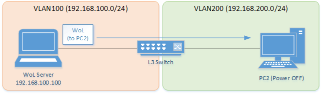
- Enables directed broadcast forwarding for VLAN #200.
- Uses the ACL to only allow WoL packets (UDP packets sent to 9 ports) from the WoL server (192.168.100.100).
- Create VLAN #100 and specify its IP address.
Yamaha(config)#interface vlan100 Yamaha(config-if)#ip address 192.168.100.240/24 Yamaha(config-if)#exit
- Create VLAN #200 and specify its IP address. Also enable directed broadcast forwarding.
Yamaha(config)#interface vlan200 Yamaha(config-if)#ip address 192.168.200.240/24 Yamaha(config-if)#ip directed-broadcast enable ... (Enable directed broadcast forwarding) Yamaha(config-if)#exit
- Create a VAM_WOL VLAN access map that restricts directed broadcasting other than WoL packets (packets addressed to UDP port 9 at IP 192.168.100.100) from the WoL server (192.168.100.100). Then apply the map to VLAN #100.
Yamaha(config)#access-list 1 10 permit udp host 192.168.100.100 host 192.168.200.255 eq 9 ... (Allow packets to be forwarded from sender 192.168.100.100 to UDP port 9 at 192.168.200.255.) Yamaha(config)#access-list 1 20 deny any any host 192.168.200.255 ... (Deny 192.168.200.255 packets forwarded to addresses other than indicated above.) Yamaha(config)#vlan access-map VAM_WOL ... (Create a VLAN access map that restricts directed broadcast forwarding) Yamaha(config-vlan-access-map)#match access-list 1 Yamaha(config-vlan-access-map)#exit Yamaha(config)#vlan filter VAM_WOL 100 in ... (Specify VLAN access map for VLAN #100 input)
6 Points of Caution
If directed broadcast forwarding is enabled in settings, it could potentially be used for a smurf or other attack.
7 Related Documentation
- L2 switching functions: VLAN
- Remote access functions:Remote access control
- SWX3220 Series Technical Data (Basic Functions)
- Layer 3 functions
- IPv6 basic settings
IPv6 basic settings
1 Function Overview
This product is compatible with the following IPv6 network environment settings, mainly for the purpose of maintenance (configuring the settings of the switch).
- IPv6 address settings
- Route information settings
- Neighbor cache table settings
2 Definition of Terms Used
- RA (Router Advertisement)
- This is a system that automatically sets address information and network settings for devices of the network that is associated with a router.
- IPv6 address
- The IPv6 address is 128 bits expressed as hexadecimal. The address is divided into eight fields delimited by “:” with 16 bits in each field.
- 2001:02f8:0000:0000:1111:2222:0000:4444
The expression can be abbreviated according to the following rules.
- If the beginning of a field is a zero, the zero can be omitted.
- A field that consists of four zeros can be abbreviated as a single zero.
- Multiple fields consisting only of consecutive zeros can be abbreviated as “::” in only one location for the entire address.
Applying these rules to the above address, we get the following.
- 2001:2f8::1111:2222:0:4444
- IPv6 link local address
- This is an address that is only valid within the same segment, and is in the following range.
- [Start]FE80:0000:0000:0000:0000:0000:0000:0000
- [End]FE80:0000:0000:0000:FFFF:FFFF:FFFF:FFFF
3 Function Details
3.1 IPv6 address settings
This product lets you specify the IPv6 address and prefix length for a VLAN interface.
As the setting method, both fixed settings and automatic settings via RA (router advertisement) are supported.
- In order to specify an IPv6 address, IPv6 functionality must be enabled for the corresponding VLAN interface.
- To enable IPv6 functionality, use the ipv6 enable command.
- When IPv6 functionality is enabled, an IPv6 link local address is automatically assigned.
- To set a fixed/automatic IPv6 address, use the ip address command.
- For IPv6 addresses, 5 global addresses (including automatically specified) and 1 link local address can be specified per VLAN interface.
A maximum of 256 IPv6 addresses can be specified for the entire system.
The IPv6 address that is allocated to a VLAN interface can be checked using the show ipv6 interface command.
3.2 Route information settings
This product refers to a routing table when sending syslog messages and when sending out voluntary IPv6 packets as a IPv6 host for NTP-based time adjustments and so on.This product uses the following functions to perform the routing table operations.
- Set VLAN interface route information
- Set default gateway
- Set static route information
- Show route information
3.2.1 VLAN interface route information
When an IPv6 address is specified for a VLAN interface, the correspondence between the network address and the VLAN ID is automatically specified by this product as route information.
When IPv6 addresses set for the VLAN interface are released, the above settings are deleted.
3.2.2 Set default gateway
The destination for IPv6 packets sent to network addresses that are not set in the routing table can be set as the default gateway on this product.
- To set the default gateway, use the ipv6 route command.
- To show the default gateway, use the show ipv6 route command.
3.2.3 Set static route information
A static route to the destination network address (the gateway address to which packets will be sent) can be set on this product.
- Static route information is set using the ipv6 route command.
- Static route information is displayed using the show ipv6 route command.
3.2.4 Routing table and route selection
You will use the following two types of table to specify routing information.
- RIB (Routing Information Base: IP routing table)
- FIB (Forwarding Information Base: IP forwarding table)
The roles of each are explained below.
- RIB
RIB (Routing Information Base: IP routing table) is a database that stores various routing information.
- A route is registered in the RIB in the following cases.
- When an IPv6 address is assigned to a VLAN interface
- When a static route or a default gateway are specified manually
- To check the RIB, use the show ipv6 route database command.
- A route is registered in the RIB in the following cases.
- FIB
FIB (Forwarding Information Base: IP forwarding table) is a database that is referenced when deciding how to forward IP packets.
Of the routes that are registered in the RIB, the FIB registers only the route that is determined to be “optimal” and is actually used for forwarding packets.
- The conditions by which a route is determined to be optimal are as follows.
- The corresponding VLAN interface is in the link up state
- If multiple routes to the same destination are registered in the RIB, only one is decided in the following order of priority
- A route whose gateway has a higher IP address value takes priority
- To check the FIB, use the show ipv6 route command.
- The conditions by which a route is determined to be optimal are as follows.
3.3 Neighbor cache table settings
When sending IPv6 packets, this product uses Neighbor Discovery Protocol to obtain the MAC addresses from the IPv6 addresses.
The correspondence between IPv6 address and MAC address is saved in the neighbor cache table with the following specifications.
- The neighbor cache entries saved in the neighbor cache table manage the following information.
- IPv6 address
- MAC address
- VLAN interface
- Up to 8192 entries are stored in the neighbor cache table, including dynamic and static entries.
- Dynamic entries saved in the neighbor cache table can be cleared by using the clear ivp6 neighbors command.
- Settings for the static entries in the neighbor cache table are made using the ipv6 neighbor command. Up to 1023 items can be registered.
- Use the show ipv6 neighbor command to check the neighbor cache table.
4 Related Commands
The related commands are shown below.
For details on the commands, refer to the Command Reference.
List of related commands
| Function types | Operations | Operating Commands |
|---|---|---|
| IPv6 address settings | Enable/disable IPv6 addresses | ipv6 enable/disable |
| Set IPv6 address | ipv6 address | |
| Show IPv6 address | show ipv6 interface | |
| Set RA setting for IPv6 address | ipv6 address autoconfig | |
| Route information settings | Set default gateway | ipv6 route |
| Show default gateway | show ipv6 route | |
| Set static route information | ipv6 route | |
| Show static route information | show ipv6 route | |
| Show route information | show ipv6 route | |
| Neighbor cache settings | Set static neighbor cache entry | ipv6 neighbors |
| Show neighbor cache table | show ipv6 neighbors | |
| Clear neighbor cache table | clear ipv6 neighbors |
5 Examples of Command Execution
5.1 Setting up a IPv6 network environment (fixed settings)
In this example, the IPv6 addresses are manually set on this product, and an environment is set up for accessing the unit from a remote terminal.
- Maintenance for this product is done using the default VLAN (VLAN #1).
- The IPv6 address is set manually for the default VLAN (VLAN #1).
- Permit Web/TFTP access from hosts connected to VLAN #1.
- This sets 2001:db8:1::2/64 for the default VLAN (VLAN #1).
Yamaha#configure terminal Enter configuration commands, one per line. End with CNTL/Z. Yamaha(config)#interface vlan1 Yamaha(config-if)#ipv6 enable ... (Enable IPv6) Yamaha(config-if)#ipv6 address 2001:db8:1::2/64 ... (Set IPv6 address)
- Check the IPv6 address that was set.
Yamaha(config-if)#end Yamaha#show ipv6 interface brief Interface IP-Address Status Protocol vlan1 2001:db8:1::2/64 up up fe80::2a0:deff:fe:2/64 - Set the default VLAN (VLAN #1) to permit access from HTTP servers and TFTP servers.
Access using a remote host over the Web after settings are made.
Yamaha(config)#http-server interface vlan1 ... (Permit HTTP server access) Yamaha(config)#tftp-server interface vlan1 ... (Permit TFTP server access)
5.2 Setting up a IPv6 network environment (automatic settings using RA)
In this example, the IPv6 addresses are automatically set on this product, and an environment is set up for accessing the unit from a remote terminal.
- Maintenance for this product is done using the default VLAN (VLAN #1).
- The IPv6 address is set automatically by RA for the default VLAN (VLAN #1).
- Permit Web/TFTP access from hosts connected to VLAN #1.
- Specify RA for the default VLAN (VLAN #1).
Yamaha#configure terminal Enter configuration commands, one per line. End with CNTL/Z. Yamaha(config)#interface vlan1 Yamaha(config-if)#ipv6 enable ... (Enable IPv6) Yamaha(config-if)#ipv6 address autoconfig ... (Set RA)
- Check the IPv6 address that was obtained from RA.
Yamaha(config-if)#end Yamaha#show ipv6 interface brief Interface IP-Address Status Protocol vlan1 2001:db8::2a0:deff:fe:2/64 up up fe80::2a0:deff:fe:2/64 - Set the default VLAN (VLAN #1) to permit access from HTTP servers and TFTP servers.
Access using a remote host over the Web after settings are made.
Yamaha(config)#http-server interface vlan1 ... (Permit HTTP server access) Yamaha(config)#tftp-server interface vlan1 ... (Permit TFTP server access)
6 Points of Caution
None
7 Related Documentation
- L2 switching functions: VLAN
- Remote access functions:Remote access control
Static routing
1 Function Overview
In this product, static routing (static route information) can be used for route control in IP networks.
An administrator can explicitly register route information by entering a command.
You can set both static routes for IPv4 networks and static routes for IPv6 networks.
There are the following two types of static route information.
| Type | Description |
|---|---|
| VLAN interface route information | Route information automatically registered by setting the IP address using the ip/ipv6 address command |
| Static route information | Route information registered by route setting by ip/ipv6 route command |
Use the show ip/ipv6 route command to display the routing table.
2 Definition of Terms Used
None
3 Function Details
3.1 VLAN interface route information
Route information that is automatically registered by setting the IP address using the ip/ipv6 address command.
It is the route information of the network directly connected to this product and is associated with the interface.
Set 192.168.100.1/24 as the IP address for the VLAN1 interface and display the routing table.
Yamaha(config)# interface vlan1
Yamaha(config-if)# ip address 192.168.100.1/24
Yamaha(config-if)# exit
Yamaha(config)# exit
Yamaha#show ip route
Codes: C - connected, S - static, R - RIP
O - OSPF, IA - OSPF inter area
N1 - OSPF NSSA external type 1, N2 - OSPF NSSA external type 2
E1 - OSPF external type 1, E2 - OSPF external type 2
C 192.168.100.0/24 is directly connected, vlan1
Gateway of last resort is not set3.2 Static route information
Route information registered by route setting by ip/ipv6 route command.
You can statically set a route to a specific network or set a default gateway.
When setting the default gateway, specify 0.0.0.0/0 as the destination network.
Up to 1024 IPv4 static routes with the ip route command can be set.
Up to 1024 IPv6 static routes with the ipv6 route command can be set.
Set the gateway for the route addressed to 172.16.0.0/16 to 192.168.100.254 and display the routing table.
Yamaha(config)# ip route 172.16.0.0/24 192.168.100.254
Yamaha(config)# exit
Yamaha# show ip route
Codes: C - connected, S - static, R - RIP
O - OSPF, IA - OSPF inter area
N1 - OSPF NSSA external type 1, N2 - OSPF NSSA external type 2
E1 - OSPF external type 1, E2 - OSPF external type 2
* - candidate default
IP Route Table for VRF "default"
S 172.16.0.0/16 [1/0] via 192.168.100.254, vlan1
C 192.168.100.0/24 is directly connected, vlan1
Gateway of last resort is not setSet 192.168.100.200 as the default gateway and display the routing table.
Yamaha(config)# ip route 0.0.0.0/0 192.168.100.200
Yamaha(config)# exit
Yamaha# show ip route
Codes: C - connected, S - static, R - RIP
O - OSPF, IA - OSPF inter area
N1 - OSPF NSSA external type 1, N2 - OSPF NSSA external type 2
E1 - OSPF external type 1, E2 - OSPF external type 2
* - candidate default
IP Route Table for VRF "default"
Gateway of last resort is 192.168.100.200 to network 0.0.0.0
S* 0.0.0.0/0 [1/0] via 192.168.100.200, vlan1
S 172.16.0.0/16 [1/0] via 192.168.100.254, vlan1
C 192.168.100.0/24 is directly connected, vlan13.3 Display of routing table
There are two routing tables: an IP forwarding table (FIB) in which only route information actually used for packet forwarding is registered, and an IP routing table (RIB) in which all route information is registered.
All VLAN interface route information and static route information are registered in the IP routing table. Within this, only the route information that is actually used in the packet forwarding process is registered in the IP forwarding table.
Use the show ip/ipv6 route command to display the IP forwarding table and the IP routing table.
In the routing table, VLAN interface route information and static route information are displayed as follows.
| Type | Display |
|---|---|
| VLAN interface route information | C - connected |
| Static route information | S - static |
If no option is specified for show ip/ipv6 route, the IP forwarding table is displayed.
You can display the IP routing table by specifying the database option with show ip/ipv6 route.
You can also display summary information and specific route information only by specifying other options.
| Option | Description |
|---|---|
| IP address | Display route information used when forwarding packets to the specified IP address. |
| IP address and prefix | Display route information that matches the specified information. |
| database | Display all configured route information (IP routing table). |
| summary | Display IP routing table summary information |
For details on how to use the show ip route command, see the command reference.
3.4 Route information priority (management distance)
Route information has a priority commonly called Administrative Distance.
This is used to determine which is prioritized when route information to the same destination is registered with VLAN interface route information and static route information.
The priority of route information can be applied not only to static routing but also to dynamic routing.
The priority of static routing route information can be specified in the range of 1 to 255 using the option at the end of the ip route command.
The smaller the value, the higher the priority. In the initial state, the priority is as follows.
| Type | Initial priority | How to change priority |
|---|---|---|
| VLAN interface route information | None (overrides any other route information) | Settings cannot be changed. |
| Static route information | 1 | It can be specified in the range of 1 to 255 by the option at the end of the ip/ipv6 route command. |
3.5 Enabling the routing function
Use the ip/ipv6 forwarding command to enable/disable the routing function.
In the initial state, the routing function is enabled for both IPv4 and IPv6.
4 Related Commands
Related commands are shown below.
For details on the commands, refer to the Command Reference.
List of related commands
| Function types | Operations | Operating Commands |
|---|---|---|
| Route information settings | Set static route information | ip route / ipv6 route |
| Show static route information | show ip route / show ipv6 route | |
| Show route information | show ip route / show ipv6 route | |
| Routing function settings | Routing function settings | ip forwarding / ipv6 forwarding |
| Routing function status display | show ip forwarding / show ipv6 forwarding |
5 Points of Caution
None
6 Related Documentation
None
- SWX3220 Series Technical Data (Basic Functions)
- Layer 3 functions
- Policy-based routing
Policy-based routing
1 Function Overview
This product offers functionality for policy-based routing.
Policy-based routing uses not only destination IP addresses, as used for regular IP routing, but also a wide variety of other information as parameters for controlling packet (unicast) routing and deciding where to forward packets.
Policy-based routing technology is especially useful for situations where multiple communications occur. Regular routing forwards all packets sent to destinations within the same network via the same path, which can cause circuit congestion that increases the risk of packet losses and delays. In contrast, policy-based routing is able to prevent losses and delays of important packets by forwarding the packets via the optimal routes for the given traffic type (destination port number).
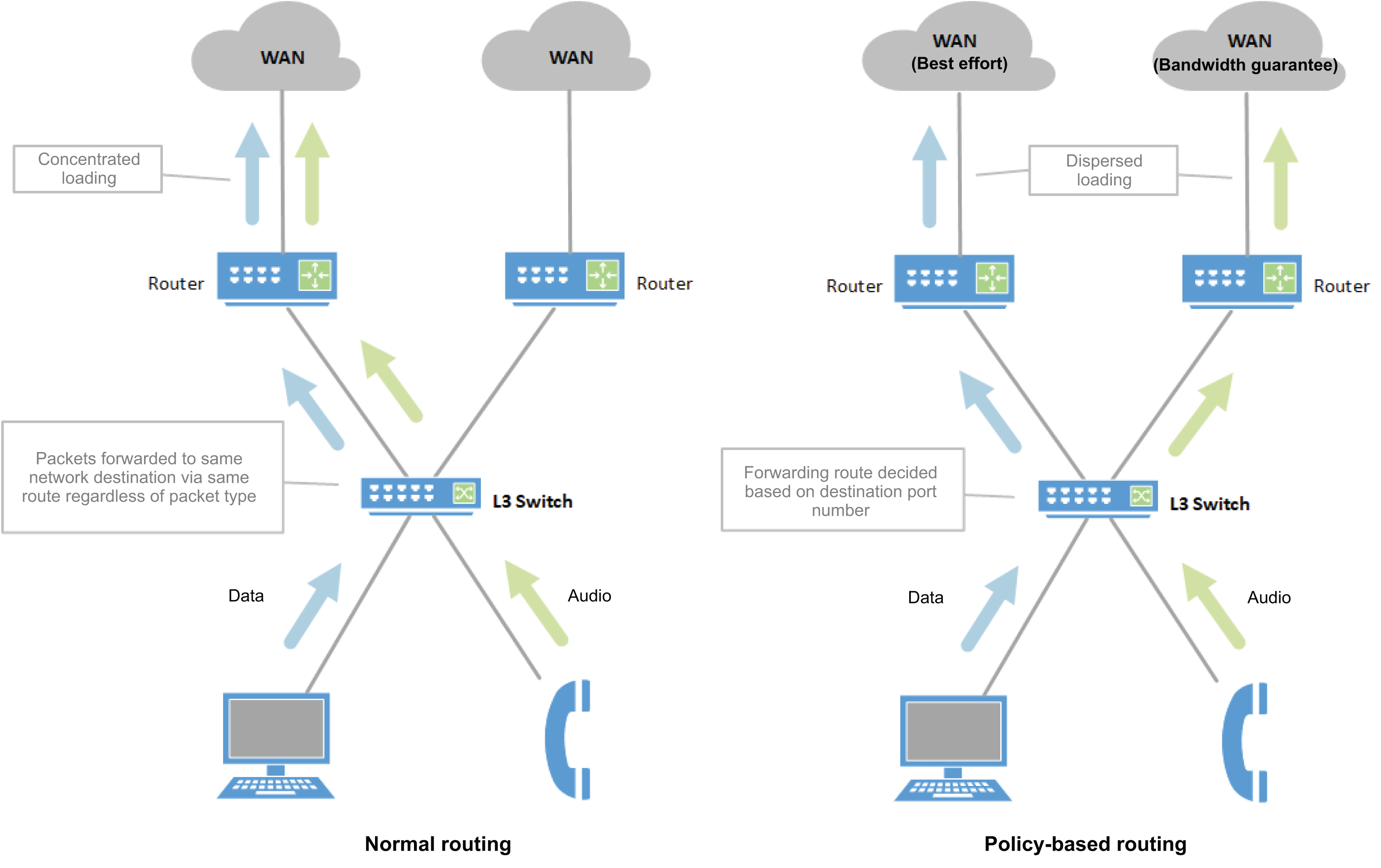
This product enables routing packets based on the following information.
- Sender/destination IPv4 address
- IP protocol type
- Sender/destination TCP/UDP port number
- Source/destination MAC address
- Source IPv6 address
2 Definition of Terms Used
- PBR
Abbreviation for policy-based routing.
- Access Control List (ACL)
This list is used to control access (decides whether to permit or to deny frames) to communication.
- Route Map
The map consists of a list of elements (entries) that are a combination of conditions specified based on access lists and processes executed for packets that match the specified conditions.
Overview of Route Map and Entries
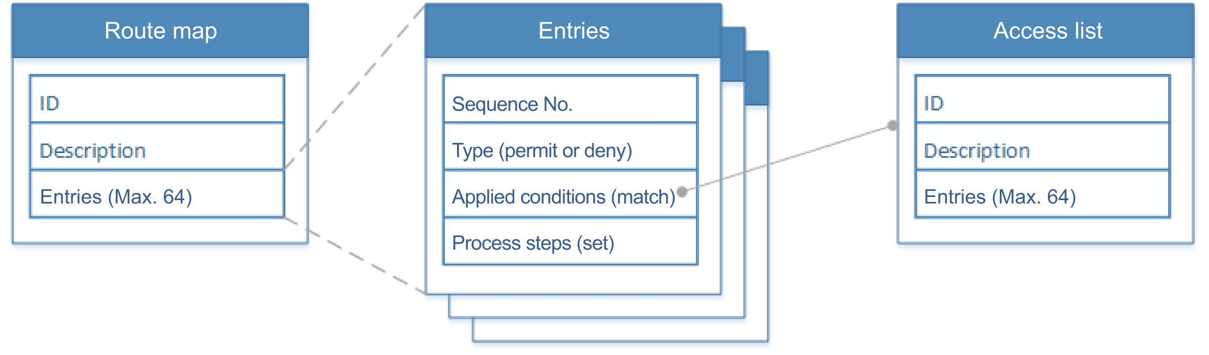
3 Function Details
PBR settings are specified by applying the route map to an interface.
The steps for specifying PBR settings are as follows.
- Generate the route map.
- Register conditions for applying the map and process steps in the route map.
- Apply the route map to the interface.
Each function is explained in more detail below.
3.1 Generating Route Maps
Route maps (and entries) are generated using the route-map command. In addition to generating a map, executing the route-map command also activates the route map mode.
In the route map mode, applicable conditions and process details can be specified for entries.
This product can generate up to 4094 route maps. Also, each route map can have up to 64 entries.
3.2 Setting Conditions and Processes
The match command is used to specify conditions for applying the process to the given entry and the set command is used to specify process settings.
The available parameter settings for each command are indicated below.
Available Parameters
| Applicable Packet Type | match | set |
|---|---|---|
| IPv4 Packet | IPv4 access list MAC access list | IPv4 next-hop (forward destination) Drop (discard) |
| IPv6 Packet | IPv6 access list | IPv6 next-hop (forward destination) Drop (discard) |
Conditional Decisions based on Access Lists
If the access list includes multiple entries (conditions) when packets are received, then a decision is made based on all entries except deny (deny entries are ignored).
If the packet matches any of the entries, then the set process is executed. If the packet does not match any of the entries, then the set process is not executed.
3.3 Applying Route Maps to Interfaces
This product can only apply route maps to VLAN interfaces. Furthermore, two different route maps can be applied to each interface, either for IPv4 packets or IPv6 packets. The ip policy route-map command can be used for IPv4 packets or the ipv6 policy route-map command for IPv6 packets.
Due to hardware limitations, the number of route maps that can be applied to interfaces is limited by the following two limitations.
- Limitations on the number of access list control conditions
- Limitations on the number of next-hop addresses
Each limitation is explained in more detail below.
- Limitations on the number of access list control conditions
Applying a route map to an interface will consume resources “equivalent to the number of control conditions registered in the access list”.
For this product, a maximum of 1524 control conditions can be registered for all interfaces.
These resources are shared for ACL or VLAN access maps, dynamic VLANs, and QoS. Specifying the resources for any of those uses reduces the number of resources available.
- Limitations on the number of next-hop addresses
If a route map that specifies a next-hop address is applied to an interface, it consumes resources other than indicated above.
For this product, a maximum of 128 next-hop addresses can be registered.
This resource is consumed each time a new next-hop address is registered, though the resource is not consumed if the same next-hop address is already specified for another interface or if Drop is specified.
Timing of Resource Consumption
The timing for when resources are consumed due to the route map is determined not by when a command applies it to the interface, but rather by when the interface to which it is applied actually links to the next-hop address (or immediately after the command if already linked when applied).
Because the resource is not consumed when the command is executed, the command itself can be successful even when no resources are available and then cause an internal error (recorded in the error log) when the resource is actually consumed.
That means maintenance personnel need to calculate the amount of resources consumed and use them in a manner that prevents an error.
3.4 Routing Received Packets
If packets are received at an interface where a route map is applied, the packets are forwarded according to route map settings.
If IPv4 packets are received, the route map applied using the ip policy route-map command is applied.
If IPv6 packets are received, the route map applied using the ipv6 policy route-map command is applied.
If the route map includes multiple entries, they are processed in sequence number order.
Sequences are executed until finished at the point the corresponding conditions are satisfied. (Subsequent sequences are ignored.)
As an example, the following route map is described below.
route-map 1 permit 10 match A set ip next-hop A.B.C.D route-map 1 permit 20 match B route-map 1 permit 30 set ip next-hop E.F.G.H route-map 1 deny 40 match C set ip next-hop I.J.K.L route-map 1 permit 50 match D set interface null
- Sequence No. 10
- When condition A is satisfied, packets are forwarded to next-hop A.B.C.D.
- If the next-hop is not included in the ARP table, then packets are forwarded by the regular routing function.
- When condition A is satisfied, packets are forwarded to next-hop A.B.C.D.
- Sequence No. 20
- Since “set” is missing, it is considered an invalid entry and the setting is ignored (does nothing).
- Sequence No. 30
- Since “match” is missing, it is considered an invalid entry and the setting is ignored (does nothing).
- Sequence No. 40
- If packets match condition C, then the “deny” entry results in forwarding by the regular routing function.
- Ignored even if “set” is included in “deny” entry.
- If packets match condition C, then the “deny” entry results in forwarding by the regular routing function.
- Sequence No. 50
- If packets match condition D, they are dropped.
- “deny” is implicit
- Because of the implicit “deny” entry in the route map, all packets are forwarded by the regular routing function.
If a route map intended for IPv4 packets includes an entry for IPv6 packets, it is ignored as an invalid entry. The converse is also true (IPv4 entry in IPv6 route map).
3.5 Enabling/Disabling the PBR Function
Use the pbr enable command to enable the PBR function or pbr disable command to disable the function.
The PBR function is enabled in factory settings. The no pbr command restores the default enabled setting.
Even if the PBR function is disabled, PBR-related settings are retained, so that previous settings can be restored if the PBR function is enabled again.
4 Related Commands
Related commands are indicated below.
For details on the commands, refer to the Command Reference.
List of related commands
| Operations | Operating Commands |
|---|---|
| Generates route map | route-map |
| Set explanatory text for route maps | description |
| Sets conditions for applying route map entries | match access-list |
| Sets process steps for route map entries (for IPv4 forwarding destinations) | set ip next-hop |
| Sets process steps for route map entries (for IPv6 forwarding destinations) | set ipv6 next-hop |
| Sets process steps for route map entries (drops packets) | set interface null |
| Applies route map to interface (for IPv4) | ip policy route-map |
| Applies route map to interface (for IPv6) | ipv6 policy route-map |
| Enables/disables the PBR function | pbr |
| Shows route map information | show route-map |
| Shows IPv4 PBR information | show ip route pbr |
| Shows IPv6 PBR information | show ipv6 route pbr |
5 Examples of Command Execution
5.1 Applying Route Maps to Interfaces
5.1.1 Setting IPv4 Next-Hops
The following describes settings for forwarding packets from VLAN #10 for destination port #80 to next-hop 192.168.20.2.
(Due to the implicit “deny” entry, all other packets received are forwarded via the normal routing function.)
The ID number of the access list to be used is #1, the route map ID number is #1000, and the route map name is IPV4_NEXTHOP.
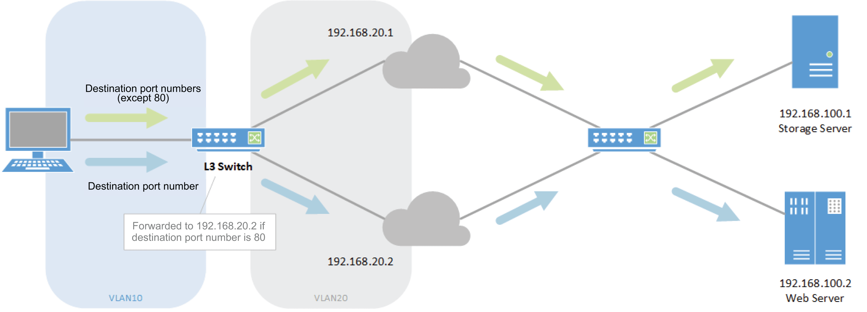
- Specify regular routing.
Yamaha(config)# ip route 0.0.0.0/0 192.168.20.1 ... (Set static route) Yamaha(config)#
- Generate access list #1.
Yamaha(config)#access-list 1 permit tcp any any eq 80 ... (Generate access list) Yamaha(config)#
- Generate an entry for route map #1000 and sequence #10. Then specify access list #1 and next-hop 192.168.20.2.
Yamaha(config)#route-map 1000 permit 10 ... (Generate route map and entries) Yamaha(config-route-map)#description IPV4_NEXTHOP ... (Specify name for route map) Yamaha(config-route-map)#match access-list 1 ... (Specify applicable conditions) Yamaha(config-route-map)#set ip next-hop 192.168.20.2 ... (Specify next hop) Yamaha(config-route-map)#exit Yamaha(config)#
- Apply route map #1000 to VLAN #10.
Yamaha(config)#interface vlan10 Yamaha(config-if)#ip policy route-map 1000 ... (Apply route map) Yamaha(config-if)#end Yamaha#
- Check that the map was applied.
Yamaha#show ip route pbr Policy Routing vlan10 Route Map: 1000, IPV4_NEXTNOP 10 permit match access-list 1 set ip next-hop 192.168.20.2
5.1.2 Setting IPv6 Next-Hops
The following describes settings for forwarding packets from a source at IPv6 address 2000:0:0:10::4/128 to next-hop 2000:0:0:20::2 at VLAN #10.
(Due to the implicit “deny” entry, all other packets received are forwarded via the normal routing function.)
The ID number of the access list to be used is #3001, the route map ID number is #2000, and the route map name is IPV6_NEXTHOP.
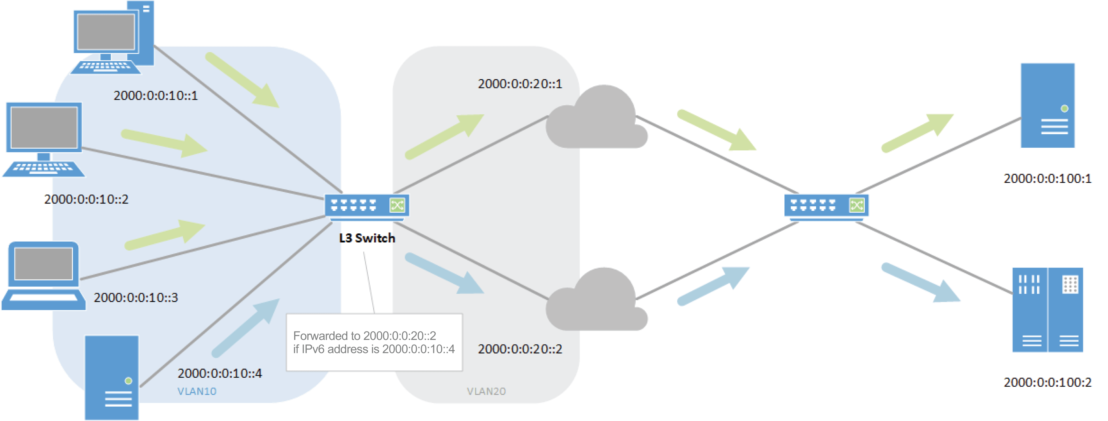
- Specify regular routing.
Yamaha(config)# ipv6 route ::/0 2000:0:0:20::1 (Sets static route) Yamaha(config)#
- Generate access list #3001.
Yamaha(config)#access-list 3001 permit 2000:0:0:10::4/128 ... (Generate access list) Yamaha(config)#
- Generate an entry for route map #2000 and sequence #10. Then specify access list #3001 and next-hop 2000:0:0:20::2.
Yamaha(config)#route-map 2000 permit 10 ... (Generate route map and entries) Yamaha(config-route-map)#description IPV6_NEXTHOP ... (Specify name for route map) Yamaha(config-route-map)#match access-list 3001 ... (Specify applicable conditions) Yamaha(config-route-map)#set ipv6 next-hop 2000:0:0:20::2 ... (Specify next hop) Yamaha(config-route-map)#exit Yamaha(config)#
- Apply route map #2000 to VLAN #10.
Yamaha(config)#interface vlan10 Yamaha(config-if)#ipv6 policy route-map 2000 ... (Apply route map) Yamaha(config-if)#end Yamaha#
- Check that the map was applied.
Yamaha#show ipv6 route pbr Policy Routing vlan10 Route Map: 2000, IPV6_NEXTHOP 10 permit match access-list 3001 set ipv6 next-hop 2000:0:0:20::2
5.1.3 Drop Settings
The following describes settings for forwarding TCP packets for destination port #80 from VLAN #10 to next-hop 192.168.20.2 and dropping TCP packets not for destination port #80.
(Due to the implicit “deny” entry, all other packets received are forwarded via the normal routing function.)
The ID number of the access list to be used is #2 and #3, the route map ID number is #3000, and the route map name is DROP.
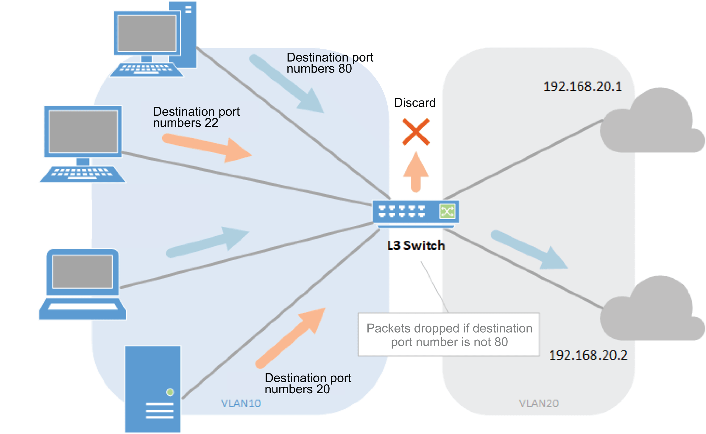
- Specify regular routing.
Yamaha(config)# ip route 0.0.0.0/0 192.168.20.1 ... (Set static route) Yamaha(config)#
- Generate access list #2.
Yamaha(config)#access-list 2 permit tcp any any eq 80 ... (Generate access list) Yamaha(config)#
- Generate access list #3.
Yamaha(config)#access-list 3 permit tcp any any ... (Generate access list) Yamaha(config)#
- Generate an entry for route map #3000 and sequence #10. Then specify access list #2 and next-hop 192.168.20.2.
Yamaha(config)#route-map 3000 permit 10 ... (Generate route map and entries) Yamaha(config-route-map)#description DROP ... (Specify name for route map) Yamaha(config-route-map)#match access-list 2 ... (Specify applicable conditions) Yamaha(config-route-map)#set next-hop 192.168.20.2 ... (Specify next hop) Yamaha(config-route-map)#exit Yamaha(config)#
- Generate an entry for sequence #20, specify access list #3, and specify drop.
Yamaha(config)#route-map 3000 permit 20 ... (Generate entries) Yamaha(config-route-map)#match access-list 3 ... (Specify applicable conditions) Yamaha(config-route-map)#set interface null ... (Drop settings) Yamaha(config-route-map)#exit Yamaha(config)#
- Apply route map #3000 to VLAN #10.
Yamaha(config)#interface vlan10 Yamaha(config-if)#ip policy route-map 3000 ... (Apply route map) Yamaha(config-if)#end Yamaha#
- Check that the map was applied.
Yamaha#show ip route pbr Policy Routing vlan10 Route Map: 3000, DROP 10 permit match access-list 2 set ip next-hop 192.168.20.2 20 permit match access-list 3 set interface null
6 Points of Caution
- PBR only supports unicast packets. Multicast packets and broadcast packets are forwarded by regular routing.
- PBR cannot be used for private or voice VLANs.
- Due to resource limitations, the PBR function cannot be used simultaneously with dynamic VLANs. If a dynamic VLAN and PBR are simultaneously specified for the same port, the dynamic VLAN is prioritized, so that the PBR does not function.
- Conditions might not be determined correctly for fragment packets. Specifically, if layer 4 information (source port number, destination port number, and various TCP flags) is included in the conditions, correct information cannot be determined because the information is not included in the second and subsequent fragment packets. If there is a possibility of processing fragment packets, do not include layer 4 information in the conditions.
- The PBR function will even forward packets received addressed to itself to the next-hop if they match the specified conditions. To not forward all packets received addressed to itself (for processing by itself), add an entry (deny entry) in route map sequence #1 that results in regular routing of packets received addressed to itself.
7 Related Documentation
- Traffic Control Functions: ACL
OSPF
1 Protocol Overview
The open shortest path first (OSPF) protocol is a type of interior gateway protocol (IGP). It is a link status type dynamic routing protocol based on graphing theory.
This product supports the following OSPF protocol version.
- OSPFv2 (RFC2328)
Designed for IPv4 networks, it solves scaling limitations involved in distance-vector type IGPs such as the routing information protocol (RIP).
It offers the following characteristics compared to RIP.
- Propagation is faster when the path changes.
- Failure detection is faster, such as if a device failure occurs.
- Overall networks can be managed divided into several separate areas.
- It specifies the way non-OSPF protocols handle paths (external paths).
- The complicated protocol requires significant CPU power and memory.
- OSPFv3 (RFC5340)
This protocol is consistent with OSPFv2 specifications, but is designed for IPv6 networks.
It offers the following characteristics compared to the IPv6-compatible interior gateway protocol RIPng.
- Path stabilization is faster when path information changes.
- Overall networks can be managed divided into several separate areas.
- It specifies how to handle paths obtained by non-OSPFv3 protocols (external paths).
- The complicated protocol requires significant CPU power and memory.
- A link local address is used to synchronize databases, except when using virtual links.
- OSPF packet authentication was removed from OSPFv3 specifications.
- An instance ID is assigned to interfaces because multiple OSPFv3 routing domains can be specified for the same link.
The basic concepts and algorithms in OSPFv3 are almost the same as OSPFv2.
However, it also involves several dissimilarities due to differences between IPv4 and IPv6 protocols and some basic conceptual changes.
The main differences are as follows.
This page provides an overview of the OSPF protocol.
For more details about commands and settings for actually configuring an OSPF network and for setting examples, refer to the Related Documentation section.
2 Definition of Terms Used
| Notation for RFC | Abbreviation | Notation for This Page |
|---|---|---|
| Router ID | - | Router ID |
| Internal Router | - | Internal Router |
| Area Border Router | ABR | Area Border Router |
| AS Boundary Router | ASBR | AS Border Router |
| Link State Advertisement | LSA | Link State Advertisement |
| Link State Database | LSDB | Link State Database |
| Designated Router | DR | Designated Router |
| Backup Designated Router | BDR | Backup Designated Router |
| Neighbor | - | Neighboring Router |
| Adjacency | - | Adjacent Router |
| Virtual Link | - | Virtual Link |
| AS External route | - | External Route |
3 Number of Routes and Recommended Number of Neighbors
The number of routes and recommended neighbors supported by OSPFv2 and OSPFv3 are indicated below.
| Protocol | Routes | Recommended Neighbors |
|---|---|---|
| OSPFv2 | 8192 | 50 |
| OSPFv3 | 8192 | 50 |
4 Function Overview
4-1. OSPF Areas
OSPF divides networks into separate areas for managing route information separately for each area.
With a backbone area positioned at the center of the OSPF network, other areas are positioned as appropriate for the given application.
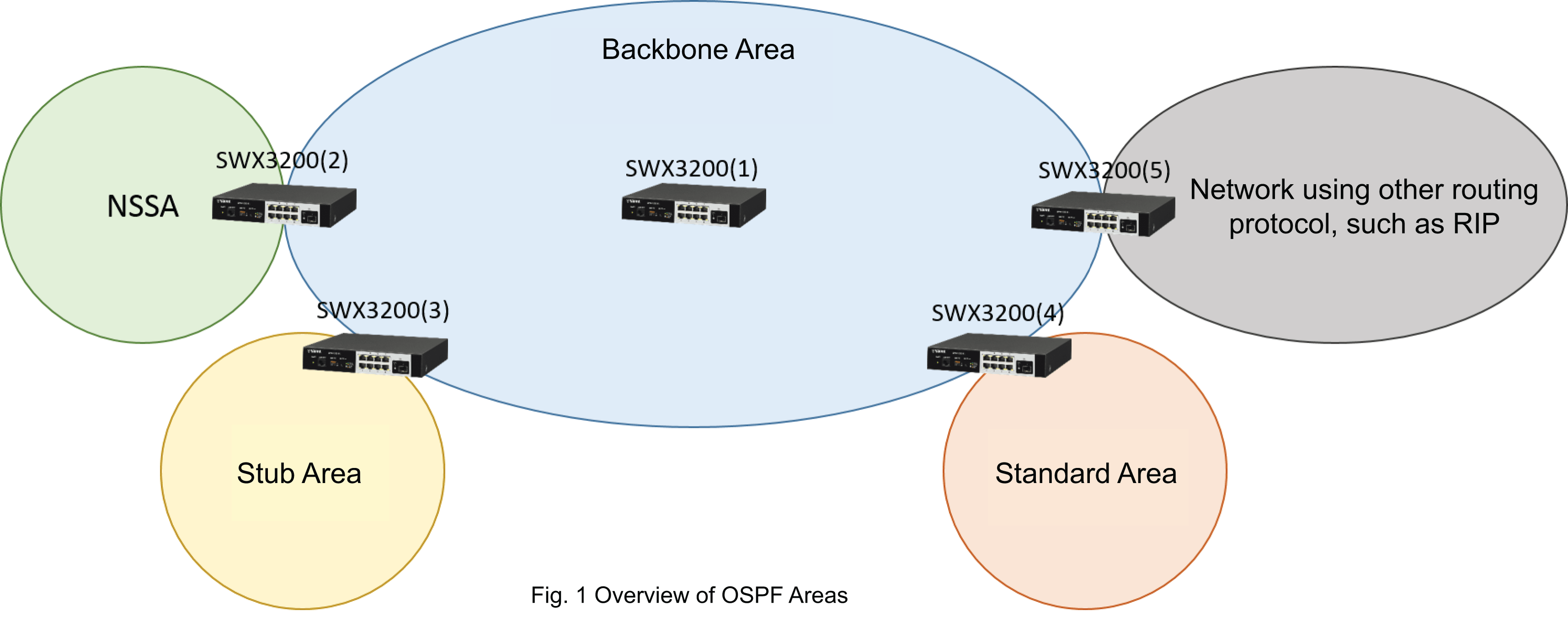
There are four types of OSPF areas.
| Area Type | Description |
|---|---|
| Backbone Area | This central area is required for OSPF networks. The area ID is predefined to be “0.0.0.0”. Non-backbone areas must connect directly to the backbone area. Area border routers (ABR), located on the border between the backbone and other areas, exchange route information between areas. |
| Stub Area | Stub areas are provided so devices with limited memory or other resources can use OSPF. Compared to backbone and standard areas, stub areas involve the following limitations. - The default route advertised by the area border router (ABR) is used for routing to external destinations within the stub area. - An AS border router (ASBR) cannot be located within the stub area. - Route information being advertised from the backbone area to other areas can be restricted. - Does not support virtual links. |
| NSSA (Not So Stubby area) | These areas are provided as an extension to stub areas. Unlike stub areas, AS border routers (ASBR) can be located in the NSSA and small amounts of external route information can be input. Compared to backbone and standard areas, NSSA involve the following limitations. - The default route advertised by the area border router (ABR) is used for routing to external destinations within the stub area. - Route information being advertised from the backbone area to other areas can be restricted. - Does not support virtual links. |
| Standard Area | Areas not indicated above. There are no significant limitations on advertising route information. |
Devices associated with OSPF areas are referred to as OSPF routers and are identified by unique router ID settings.
There are three types of OSPF routers, depending on where they are located.
| Type | Abbreviation | Description |
|---|---|---|
| Internal Router | - | Routers located only with certain areas. The SWX3200 (1) router in Fig. 1 is an internal router. |
| Area Border Router | ABR | Routers located on the border between the backbone and other areas. SWX3200 (2), SWX3200 (3), and SWX3200 (4) in Fig. 1 are area border routers. |
| AS Border Router | ASBR | These routers are positioned at the border between networks using non-OSPF routing protocols and OSPF networks. The SWX3200 (5) router in Fig. 1 is an AS Border router. |
4-2. OSPF Messages
OSPF determines topology within and outside areas by sending information called link state advertisements (LSA) between routers. Received LSA are combined with the device’s own LSA to create a link state database (LSDB) that is used to manage the link state. Since OSPF routers in the same area are constantly synchronized to retain the same LSDB, obstructions can be detected so that communication can be restored via an alternative route, even if route information changes occur, because changes can be synchronized with the LSDB in another OSPF router.
OSPF uses the following messages to search for other OSPF routers in the same area and exchange route information.
| Message Type | Message | Abbreviation | Description |
|---|---|---|---|
| 1 | Hello | Hello | Used to search for other OSPF routers in the same area. The router ID included in the message is also used to choose the designated router. The following message is used to exchange route information with other OSPF routers with which a neighbor relationship was determined using the Hello message. |
| 2 | Database Description | DD | All LSA link state headers retained are included in a DD message and sent to OSPF routers for which a neighbor relationship was established. The OSPF router that receives the DD message compares the link state header information to its own LSBD. If any LSA need to be obtained or updated, a DD message is sent to the sender to request LSA. |
| 3 | Link State Request | LSR | Based on the DD message received, if any LSA needs to be obtained or updated, the LSA is requested using an LSR message. |
| 4 | Link State Update | LSU | Used to send LSA notifications. Multiple LSA can be included. |
| 5 | Link State Ack | LSAck | LSU confirmation response. |
The following describes the process flow up to using the above message to obtain LSA.
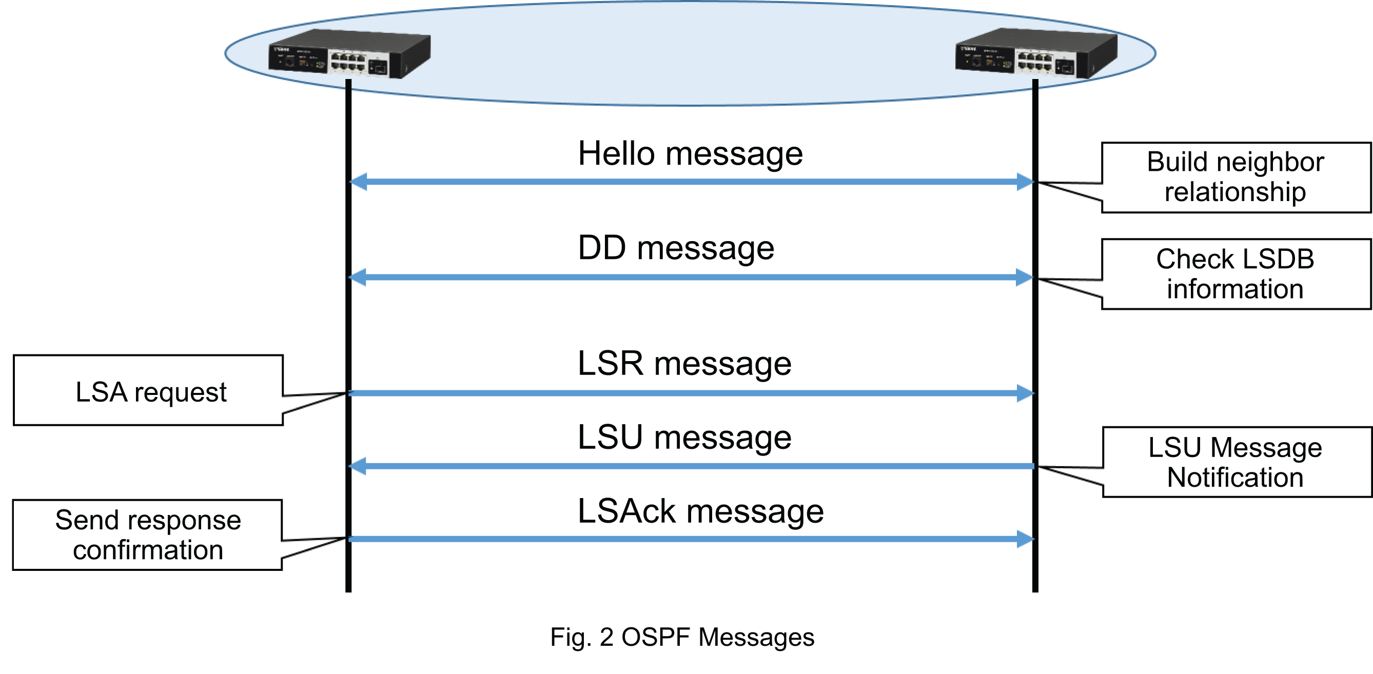
4-3. Designated Router (DR) and Backup Designated Router (BDR)
In networks that support multicasting, OSPF selects a designated router (DR) and backup designated router (BDR) from among OSPF routers in that area. The designated router serves the role of advertising any route information changes to other OSPF routers in the area. That can reduce unnecessary exchanges of LSA data by eliminating route information change notifications by other devices. If the designated router fails, then the backup designated router is changed to the designated router.
OSPF routers not selected as the designated router or backup designated router can only exchange LSA information with the designated router or backup designated router.
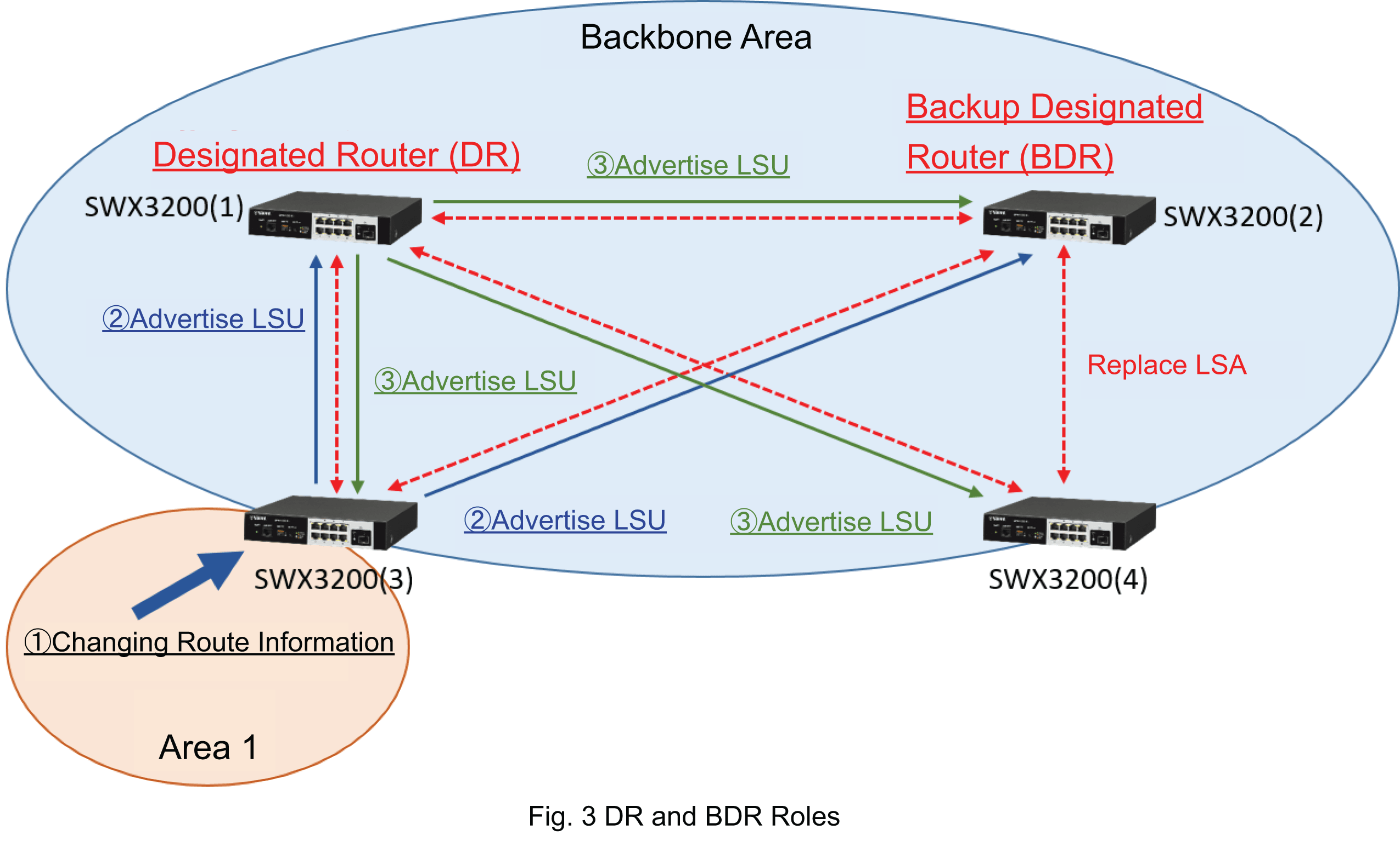
For example, given the configuration in Fig. 2, if route information changes due to an arbitrary network failure in area 1, then SWX3200 (3) will advertise the route information change to the backbone area, so that the LSU is sent to the designated router SWX3200 (1) and backup designated router SWX3200 (2). When the designated router receives the LSU, it advertises it to other OSPF routers in the area. In that case, the backup designated router does not advertise the LSU.
4-4. Neighboring Routers and Adjacent Routers
If two OSPF routers in the same OSPF area use the Hello message to confirm they are mutually OSPF routers, then that relationship is referred to as being “neighboring”. The relationship of being able to directly exchange LSA information is referred to as being “adjacent”. Based on these relationships, OSPF routers are classified as either neighboring routers or adjacent routers.
| Type | Description |
|---|---|
| Neighboring Routers | OSPF routers identified as being in the same area by the Hello message. SWX3200 (3) and SWX3200 (4) in Fig. 2 are mutually neighboring routers. |
| Adjacent Routers | OSPF routers that directly exchange LSA information after being identified as being in the same area by the Hello message. From the perspective of SWX3200 (1), SWX3200 (2), SWX3200 (3), and SWX3200 (4) are adjacent routers. |
4-5. Link State Advertisements (LSA)
There are six types of link state advertisements (LSA) depending on the circumstances of use and type of advertisement, as indicated below.
| LSA Type | Type | Source | Description |
|---|---|---|---|
| 1 | Router LSA | All OSPF routers | LSA used only within the same area and that includes link information for the source OSPF router. |
| 2 | Network LSA | DR | LSA used only within the same area and that includes a list of OSPF routers kept in the DR. |
| 3 | Network Summary LSA | ABR | Used to advertise route information reachable via the backbone area to areas connected to the backbone area. Also used to advertise route information for areas connected to the backbone area to the backbone area. |
| 4 | ASBR Summary LSA | ABR | Used to advertise ASBR router ID values, metric values up to the ASBR, and other information. |
| 5 | AS external LSA | ASBR | Used to advertise external routes to OSPF areas. If an AS external LSA is advertised to a NSSA, then it is converted to a type-7 NSSA AS external LSA before advertising. |
| 7 | NSSA AS external LSA | ASBR within NSSA | Used to advertise external routes to NSSA areas. If external routes are to be advertised from an ABR within an NSSA to the backbone area, then it is converted to a type-5 AS external LSA before advertising. |
4-6. Virtual Link
OSPF requires that all areas are connected directly to the backbone area. However, for some networks it is physically impossible to connect directly to the backbone area. In such cases, a virtual link can be used to logically connect to the backbone area.
For example, to add a network to an existing OSPF network that was configured first, the additional network does not necessarily need to be connected directly to the backbone area. Rather, it can be connected to the nearest standard area and then a virtual link used to connect it logically to the backbone area.
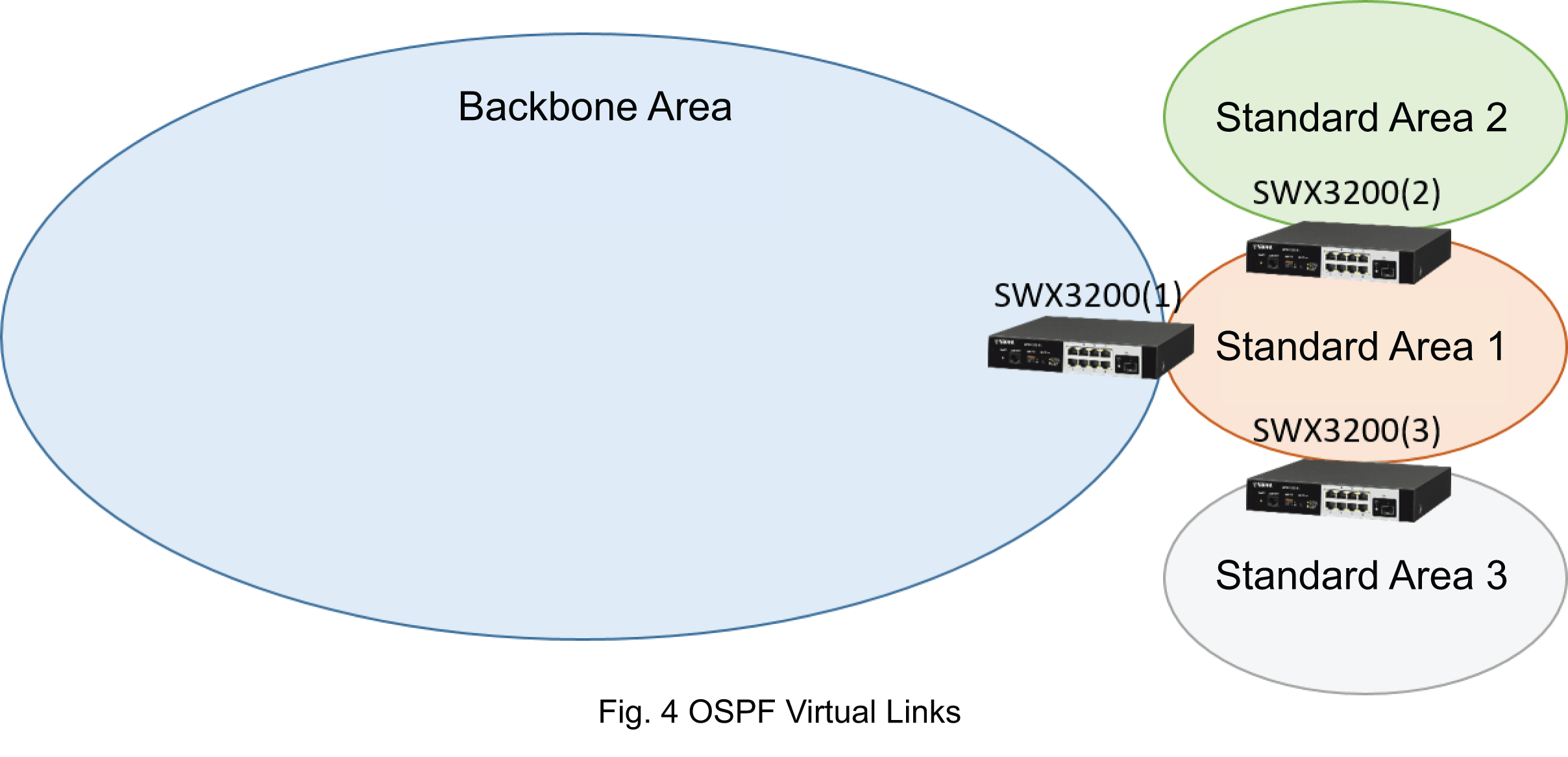
Fig. 4 shows an example of adding standard areas 2 and 3 to an OSPF network with standard area 1 connected to the backbone area. By using Summary-LSA to exchange route information between standard area 2 and the backbone area via standard area 1, the backbone area treats standard area 2 as a directly connected point-to-point network.
That means route information exchanged between standard areas 2 and 3 passes via the backbone area, but actual communication does not necessarily pass via the backbone area. If a cost calculation of each link derives that the shortest route is not via the backbone area, then communication between standard areas 2 and 3 will pass through only standard area 1.
5 Points of Caution
None
6 Related Documentation
- SWX3220 Series Technical Data (Basic Functions)
- Layer 3 functions
- OSPF
- OSPF setting guide
OSPF setting guide
The following describes basic guidelines for configuring OSPF settings.
Enabling OSPF
To enable OSPF, enter the following command in global configuration mode.
That enables the OSPF routing process and switches to the OSPF settings mode (OSPF mode).
For OSPFv2:
Yamaha(config)# router ospf [PROCESS_ID]
For OSPFv3:
Yamaha(config)# router ipv6 ospf [PROCESS_ID]
Specifying the Router ID
Set the router ID of this product. The router ID is an identification number that uniquely identifies each OSPF router in the network. That means router IDs must be specified without any duplication between the multiple routers involved.
Yamaha(config-router)# router-id X.X.X.X
Several methods are available for specifying OSPF router IDs. Decide which to use based on the following priority order.
- Use the router-id command setting value specified in the OSPF mode.
However, in the OSPFv2 mode, the same setting is possible for the ospf router-id command as well.
- Use the router-id command setting value specified in the global configuration mode.
- Use the highest IP address value specified for the VLAN interface.
To prevent using an unintended IP address as the router address, we recommend using clearly specified router ID values.
Selecting Interfaces that will use OSPF
Use the network command in the OSPF mode to select the interfaces where OSPF will be used.
The following will position the interface that retains IP addresses within the 192.168.100.0/24 range in the backbone area.
Yamaha(config-router)# network 192.168.100.0 0.0.0.255 area 0
The network command can be used with one command setting to assign multiple interfaces to OSPF areas.
However, beware that adding interfaces later might unintentionally enable OSPF.
Specifying Area Types
Use the area command to specify area types defines by the OSPF protocol.
- Position the interface with IP addresses within the 192.168.100.0/24 range in area 1 (standard area).
Yamaha(config-router)# network 192.168.100.0 0.0.0.255 area 1
- Position the interface with IP addresses within the 192.168.100.0/24 range in area 1 (stub area).
Yamaha(config-router)# network 192.168.100.0 0.0.0.255 area 1 Yamaha(config-router)# area 1 stub
- Position the interface with IP addresses within the 192.168.100.0/24 range in area 1 (full-stub area).
Yamaha(config-router)# network 192.168.100.0 0.0.0.255 area 1 Yamaha(config-router)# area 1 stub no-summary
- Position the interface with IP addresses within the 192.168.100.0/24 range in area 1 (NSSA).
Yamaha(config-router)# network 192.168.100.0 0.0.0.255 area 1 Yamaha(config-router)# area 1 nssa
- Position the interface with IP addresses within the 192.168.100.0/24 range in area 1 (full-NSSA area).
Yamaha(config-router)# network 192.168.100.0 0.0.0.255 area 1 Yamaha(config-router)# area 1 nssa no-summary
To specify a stub area, all the OSPF routers in the area must be specified as in a stub area.
To specify a NSSA area, all the OSPF routers in the area must be specified as in an NSSA area.
Advertising, Collecting, and Filtering Route Information
Advertising can be restricted, route information collected, or route information filtered for inputting external route information into OSPF, such as information handled for specifying a static route or for the RIP, or to exchange route information within OSPF areas. The figure below shows a diagram of route information operations when an area border router (ABR) and autonomous system border router (ASBR) are both located in standard, NSSA, and stub areas. The underlined commands are used for route information operations.
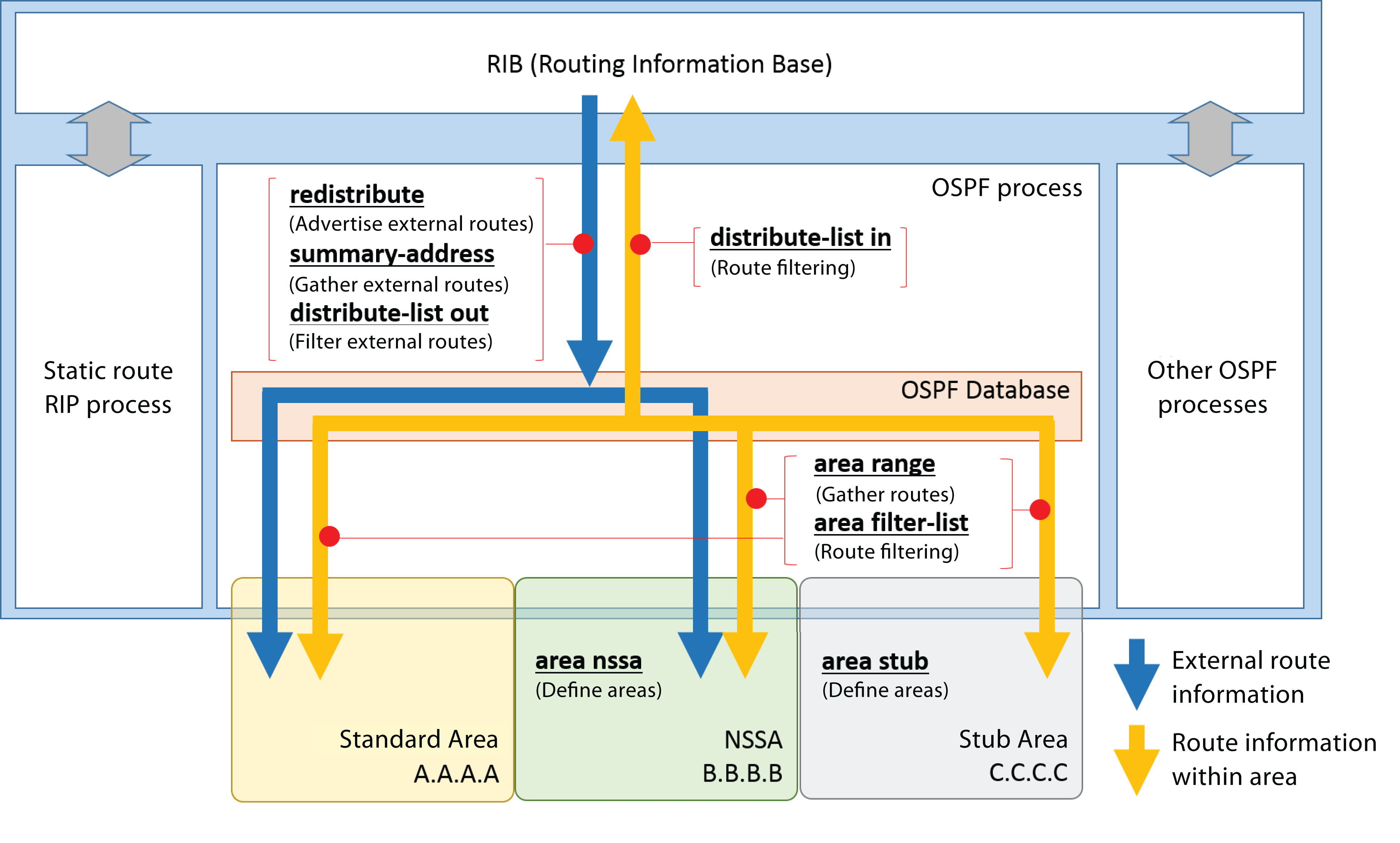
Settings for Route Information within OSPF Areas
192.168.1.0/24, 192.168.2.0/24, and 192.168.200.0/24 information notified from area A.A.A.A and held as route information in OSPF areas is collected at 192.168.0.0/16 and advertised to other areas.
Yamaha(config-router)# area A.A.A.A range 192.168.0.0/16
Of the 192.168.1.0/24, 192.168.2.0/24, and 192.168.200.0/24 information notified from area A.A.A.A and held as route information in OSPF areas, only 192.168.2.0/24 is not advertised to other areas.
Yamaha(config-router)# area A.A.A.A range 192.168.2.0/24 not-advertise
Of the 192.168.1.0/24, 192.168.2.0/24, and 192.168.200.0/24 information notified from area A.A.A.A and held as route information in OSPF areas, only 192.168.2.0/24 is not advertised to other areas.
Yamaha(config)# access-list 1 deny 192.168.2.0 0.0.0.255 Yamaha(config)# access-list 1 permit any Yamaha(config)# router ospf Yamaha(config-router)# area A.A.A.A filter-list access 1 in
The 192.168.2.0/24 route information is not advertised to stub area C.C.C.C.
Yamaha(config)# access-list 1 deny 192.168.2.0 0.0.0.255 Yamaha(config)# access-list 1 permit any Yamaha(config)# router ospf Yamaha(config-router)# area C.C.C.C filter-list access 1 out
Of the 192.168.1.0/24, 192.168.2.0/24, and 192.168.200.0/24 information held as route information in OSPF areas, only 192.168.2.0/24 is not advertised to the RIB.
Yamaha(config)# access-list 1 deny 192.168.2.0 0.0.0.255 Yamaha(config)# access-list 1 permit any Yamaha(config)# router ospf Yamaha(config-router)# distribute-list 1 in
Settings for External Route Information
The external routes information acquired by the RIP are advertised to the OSPF areas.
Yamaha(config-router)# redistribute rip
External route information at 172.16.1.0/24, 172.16.2.0/24, and 172.16.200.0/24 is collected at 172.16.0.0/16 and advertised to OSPF areas.
Yamaha(config-router)# summary-address 172.16.0.0/16
Of the 172.16.1.0/24, 172.16.2.0/24, and 172.16.200.0/24 external route information, only 172.16.2.0/24 is not advertised to OSPF areas.
Yamaha(config-router)# summary-address 172.16.2.0/24 not-advertise
Of the external route information acquired at RIP, only 203.0.113.0/24 is not entered in the OSPF routing table.
Yamaha(config)# access-list 1 deny 203.0.113.0 0.0.0.255 Yamaha(config)# access-list 1 permit any Yamaha(config)# router ospf Yamaha(config-router)# distribute-list 1 out rip
Using a Virtual Link
In this example, a virtual link is used to connect standard area 2 to an OSPF network consisting of a backbone area and standard area 1.
Set the SWX3200 router ID to 172.16.1.1 and the SWX3200 router ID to 172.16.2.1.
Assign 172.16.1.0/24 for the backbone area network, 172.16.2.0/24 for the standard area 1 network, and 172.16.3.0/24 for the standard area 2 network.
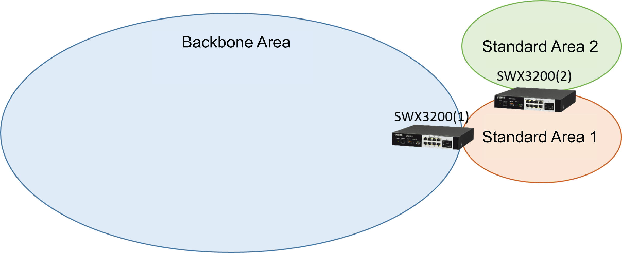
SWX3200 Settings
Yamaha(config-router)# network 172.16.3.0 255.255.255.0 area 2 Yamaha(config-router)# area 1 virtual-link 172.16.2.1
SWX3200Settings
Yamaha(config-router)# network 172.16.1.0 255.255.255.0 area 0 Yamaha(config-router)# network 172.16.2.0 255.255.255.0 area 1 Yamaha(config-router)# area 1 virtual-link 172.16.1.1
Using OSPF Authentication
OSPF enables packet authentication.
Using OSPF authentication can prevent accidentally specifying routers as OSPF neighbors.
To use OSPF authentication, authentication settings must be similarly configured for all devices involved in exchanging OSPF packets via an interface with OSPF authentication enabled.
Settings for Simple Password Authentication
The following specifies simple password authentication (authentication key: “yamaha”) for the vlan1 interface in the backbone area.
! router ospf area 0 authentication ! interface vlan1 ip ospf authentication-key yamaha !
Settings for MD5 Digest Access Authentication
The following specifies MD5 digest access authentication (authentication key: “1a2b3c4d5e6f7890”) for the vlan1 interface in the backbone area.
! router ospf area 0 authentication message-digest ! interface vlan1 ip ospf message-digest-key 1 md5 1a2b3c4d5e6f7890 !
Checking the OSPF Status
Show the OSPF database information.
Yamaha# show ip ospf database
Show information for interfaces operating OSPF.
Yamaha# show ip ospf interface
Show information for the VLAN1 interface operating OSPF.
Yamaha# show ip ospf interface vlan1
Show OSPF neighbor information.
Yamaha# show ip ospf neighbor
Show virtual link information.
Yamaha# show ip ospf virtual-links
Show route information held by OSPF processes.
If multiple routes exist for a single destination, the metric value is used to select the optimal route and register in the RIB.
Yamaha# show ip ospf route
- SWX3220 Series Technical Data (Basic Functions)
- Layer 3 functions
- OSPF
- OSPFv2 setting example
OSPFv2 setting example
This page describes an example of SWX3200 settings configured based on the diagram shown below.
Example Diagram
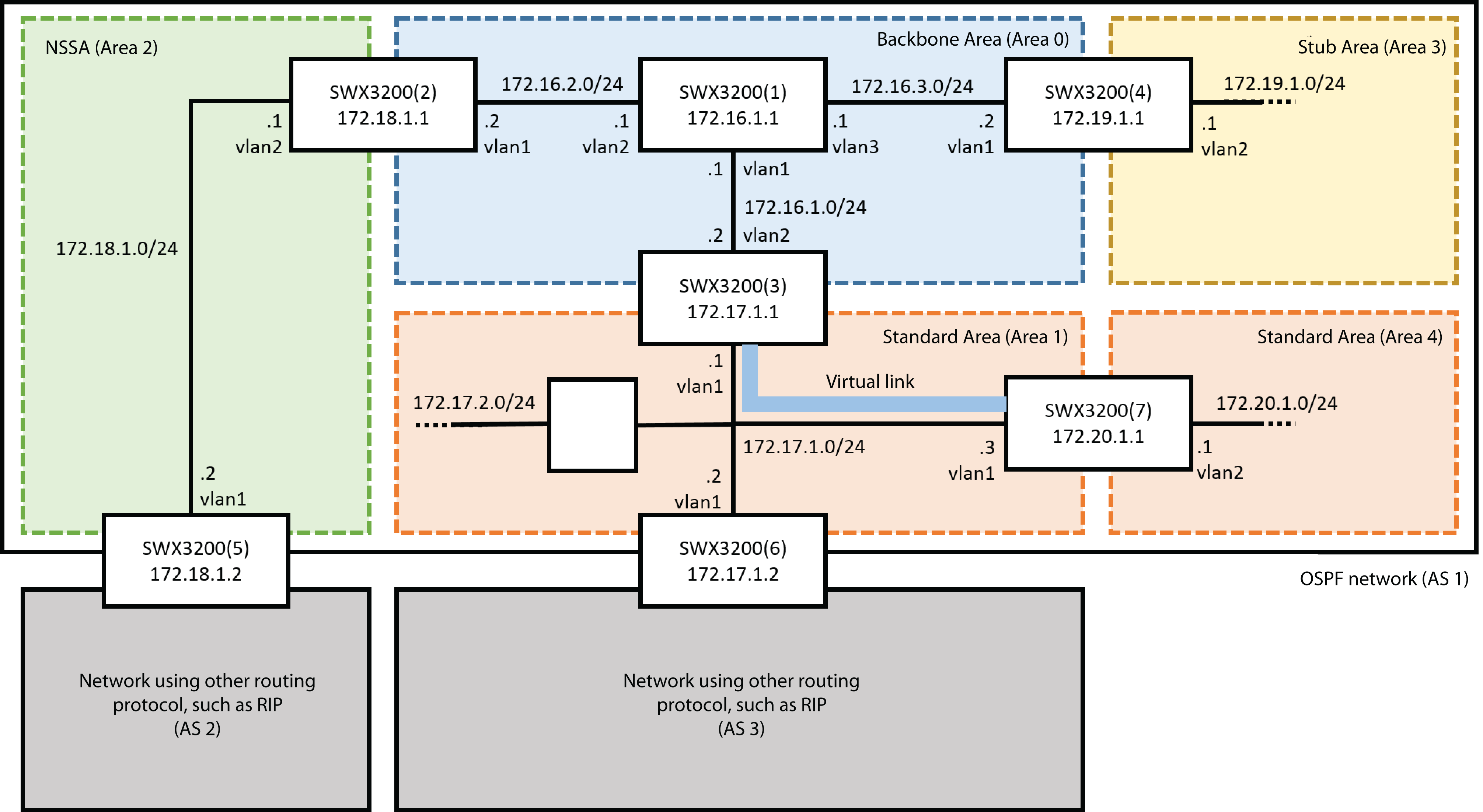
SWX3200 (1) Setting Example
SWX3200 (1) is a router located within the backbone area.
Use the network command to register the three networks connected to vlan1 to 3 as area 0.
! vlan database vlan 2-3 state enable ! interface port1.1 switchport switchport mode access ! interface port1.2 switchport switchport mode access switchport access vlan 2 ! interface port1.3 switchport switchport mode access switchport access vlan 3 ! interface vlan1 ip address 172.16.1.1/24 ! interface vlan2 ip address 172.16.2.1/24 ! interface vlan3 ip address 172.16.3.1/24 ! router ospf ospf router-id 172.16.1.1 network 172.16.1.0 255.255.255.0 area 0 network 172.16.2.0 255.255.255.0 area 0 network 172.16.3.0 255.255.255.0 area 0 !
SWX3200 (2) Setting Example
SWX3200 (2) is an area border router (ABR) for the backbone area (area 0) and NSSA (area 2).
Use the network command to register the address 172.16.2.0/24 connected to vlan1 as area 0.
Use the network command to register the address 172.18.1.0/24 connected to vlan2 as area 2.
Use the area command to register area 2 as an NSSA. Specify “default-information-originate” to notify the default route from SWX3200 (2) to area 2.
! vlan database vlan 2 state enable ! interface port1.1 switchport switchport mode access ! interface port1.2 switchport switchport mode access switchport access vlan 2 ! interface vlan1 ip address 172.16.2.2/24 ! interface vlan2 ip address 172.18.1.1/24 ! router ospf ospf router-id 172.18.1.1 network 172.16.2.0 255.255.255.0 area 0 network 172.18.1.0 255.255.255.0 area 2 area 2 nssa default-information-originate !
SWX3200 (3) Setting Example
SWX3200 (3) is an area border router (ABR) for the backbone area (area 0) and the standard area (area 1).
Use the network command to register the addresses 172.17.1.0/24, 172.17.2.0/24 connected to vlan1 as area 1.
Use the network command to register the address 172.16.1.0/24 connected to vlan2 as area 0.
To enable virtual adjacency between areas 4 and 0, use the area command to configure a virtual link.
Collect the two networks from area 1 at 172.17.0.0/16 and advertise them to area 0.
Collect the three networks from area 0 at 172.16.0.0/16 and advertise them to area 1.
! vlan database vlan 2 state enable ! interface port1.1 switchport switchport mode access ! interface port1.2 switchport switchport mode access switchport access vlan 2 ! interface vlan1 ip address 172.17.1.1/24 ! interface vlan2 ip address 172.16.1.2/24 ! router ospf ospf router-id 172.17.1.1 network 172.17.1.0 255.255.255.0 area 1 network 172.17.2.0 255.255.255.0 area 1 network 172.16.1.0 255.255.255.0 area 0 area 1 virtual-link 172.20.1.1 area 0 range 172.16.0.0/16 area 1 range 172.17.0.0/16 !
SWX3200 (4) Setting Example
SWX3200 (4) is an area border router (ABR) for the backbone area (area 0) and the stub area (area 3).
Use the network command to register the address 172.16.3.0/24 connected to vlan1 as area 0.
Use the network command to register the address 172.19.1.0/24 connected to vlan2 as area 3.
Use the area command to register area 3 as a stub area.
! vlan database vlan 2 state enable ! interface port1.1 switchport switchport mode access ! interface port1.2 switchport switchport mode access switchport access vlan 2 ! interface vlan1 ip address 172.16.3.2/24 ! interface vlan2 ip address 172.19.1.1/24 ! router ospf ospf router-id 172.19.1.1 network 172.16.3.0 255.255.255.0 area 0 network 172.19.1.0 255.255.255.0 area 3 area 3 stub !
SWX3200 (5) Setting Example
SWX3200 (5) is an autonomous system border router (ASBR) for the NSSA (area 2) and AS2.
It is assumed that RIP, a non-OSPF routing protocol, is running within AS2 and that networks 192.168.100.0/24, 192.168.200.0/24 present.
RIP Settings
Use the network command to register the addresses 192.168.100.0/24 and 192.168.200.0/24 to be controlled.
Also, advertise the OSPF network in AS1 as the default route.
! router rip network 192.168.100.0/24 network 192.168.200.0/24 default-information originate !
OSPF Settings
Use the network command to register the address 172.18.1.0/24 connected to vlan1 as area 2.
Use the area command to register area 2 as an NSSA.
Advertise the route information acquired by RIP and the RIP interface route information to the OSPF network.
Collect the route information for 192.168.100.0/24 and 192.168.200.0/24 acquired from RIP at 192.168.0.0/16 and advertise it to area 2.
Prevent the interface running RIP from sending an OSPF Hello message.
! vlan database vlan 2 state enable ! interface port1.1 switchport switchport mode access ! interface port1.2 switchport switchport mode access switchport access vlan 2 ! interface vlan1 ip address 172.18.1.2/24 ! interface vlan2 ip address 192.168.100.1/24 ! router ospf ospf router-id 172.18.1.2 network 172.18.1.0 255.255.255.0 area 2 area 2 nssa redistribute rip redistribute connected summary-address 192.168.0.0/16 passive-interface vlan2 !
SWX3200 (6) Setting Example
SWX3200 (6) is an autonomous system border router (ASBR) for the standard area (area 1) and AS3.
It is assumed that RIP, a non-OSPF routing protocol, is running within AS3 and that networks 10.0.0.0/24, 10.0.1.0/24 present.
RIP Settings
Use the network command to register the addresses 10.0.0.0/24 and 10.0.1.0/24 to be controlled.
Also, advertise the OSPF network in AS1 as the default route.
! router rip network 10.0.0.0/24 network 10.0.1.0/24 default-information originate !
OSPF Settings
Use the network command to register the addresses 172.17.1.0/24, 172.17.2.0/24 connected to vlan1 as area 1.
Advertise the route information acquired by RIP and the RIP interface route information to the OSPF network.
Collect the route information for 10.0.0.0/24 and 10.0.1.0/24 acquired from RIP at 10.0.0.0/16 and advertise it to area 1.
Prevent the interface running RIP from sending an OSPF Hello message.
! vlan database vlan 2 state enable ! interface port1.1 switchport switchport mode access ! interface port1.2 switchport switchport mode access switchport access vlan 2 ! interface vlan1 ip address 172.17.1.2/24 ! interface vlan2 ip address 10.0.0.1/24 ! router ospf ospf router-id 172.17.1.2 network 172.17.1.0 255.255.255.0 area 1 network 172.17.2.0 255.255.255.0 area 1 redistribute rip redistribute connected summary-address 10.0.0.0/16 passive-interface vlan2 !
SWX3200 (7) Setting Example
SWX3200 (7) is an area border router (ABR) for the standard area (area 1) and the standard area (area 4).
Use the network command to register the addresses 172.17.1.0/24, 172.17.2.0/24 connected to vlan1 as area 1.
Use the network command to register the address 172.20.1.0/24 connected to vlan2 as area 4.
To enable virtual adjacency between areas 4 and 0, use the area command to configure a virtual link.
Collect the two networks from area 1 at 172.17.0.0/16 and advertise them to area 0.
! vlan database vlan 2 state enable ! interface port1.1 switchport switchport mode access ! interface port1.2 switchport switchport mode access switchport access vlan 2 ! interface vlan1 ip address 172.17.1.3/24 ! interface vlan2 ip address 172.20.1.1/24 ! router ospf ospf router-id 172.20.1.1 network 172.17.1.0 255.255.255.0 area 1 network 172.17.2.0 255.255.255.0 area 1 network 172.20.1.0 255.255.255.0 area 4 area 1 virtual-link 172.17.1.1 area 1 range 172.17.0.0/16 !
RIP
1 Protocol Overview
The routing information protocol (RIP) is a distance vector type interior gateway routing protocol (IGP) designed for TCP/IP networks.
The metric used is the number of networks (hops) passed through for forwarding to the destination. Therefore, it is not suitable for networks that require considering real-time information, such as delay times, loads, and reliability. However, settings are easy to specify and apply minimal loads, so RIP is well-suited for use in relatively small networks.
This product supports the following RIP versions.
- RIPv1 (RFC1058)
Due to requiring much smaller calculation loads than OSPF (open shortest path first), this version was especially popular when calculation devices lacked adequate capacity.
It offers the following characteristics.
- Calculation loads are extremely low.
- It cannot be used on large networks with 15 or more hops.
- It takes a long time for fully converging on routing for an entire network.
- It takes a long time to detect route problems.
- Count-to-infinity problems can occur if a link-down occurs.
- RIPv2 (RFC2453)
This version was released to solve problems with RIPv1.
RIPv2 includes the following additional functionality.
- Sending RIP packets based on multicast addresses
- Support for authentication function (simple password or MD5)
- Support for subnet masks
- Support for next-hop addressing
- RIPng (RFC2080)
This protocol is consistent with RIPv2 specifications but is designed for IPv6 networks.
No basic specification differences from RIPv2, except support for IPv6 network route information.
This page describes how to specify RIP/RIPng settings.
For more details about RIP-related commands, refer to the Related Documentation section.
2 Definition of Terms Used
None
3 Number of Routes
The number of routes supported by RIP and RIPng are indicated below.
| Protocol | Routes |
|---|---|
| RIP(v1/v2) | 1024 | RIPng | 1024 |
4 Basic Settings
The following network is used as a reference for specifying basic RIP settings.
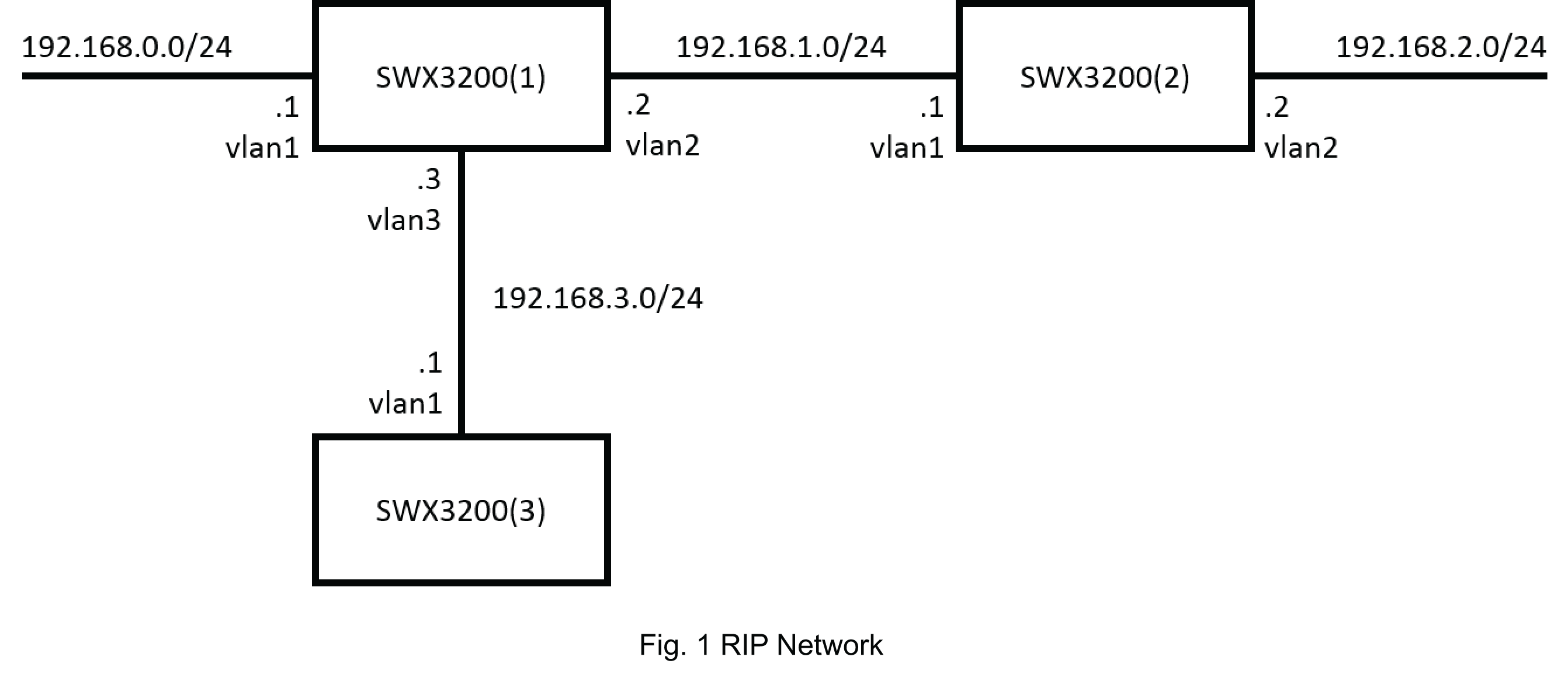
Settings at SWX3200 (1)
SWX3200 (1) is connected to three networks: 192.168.0.0/24, 192.168.1.0/24, and 192.168.3.0/24.
Use the network command to register each network.
! vlan database vlan 2-3 state enable ! interface port1.1 switchport switchport mode access ! interface port1.2 switchport switchport mode access switchport access vlan 2 ! interface port1.3 switchport switchport mode access switchport access vlan 3 ! interface vlan1 ip address 192.168.0.1/24 ! interface vlan2 ip address 192.168.1.2/24 ! interface vlan3 ip address 192.168.3.3/24 ! router rip network 192.168.0.0/24 network 192.168.1.0/24 network 192.168.3.0/24 !
Settings at SWX3200 (2)
SWX3200 (2) is connected to two networks: 192.168.1.0/24 and 192.168.2.0/24.
Use the network command to register each network.
! vlan database vlan 2 state enable ! interface port1.1 switchport switchport mode access ! interface port1.2 switchport switchport mode access switchport access vlan 2 ! interface vlan1 ip address 192.168.1.1/24 ! interface vlan2 ip address 192.168.2.1/24 ! router rip network 192.168.1.0/24 network 192.168.2.0/24 !
Settings at SWX3200 (3)
SWX3200 (3) is connected to the network 192.168.3.0/24.
Use the network command to register each network.
! interface port1.1 switchport switchport mode access ! interface vlan1 ip address 192.168.3.1/24 ! router rip network 192.168.3.0/24 !
In addition to specifying network addresses, the network command can also be used to specified VLAN interfaces.
If a VLAN interface is specified, then the networks connected directly to that VLAN interface become RIP networks.
In terms of SWX3200 (3) settings, the VLAN interface is specified as follows.
! interface port1.1 switchport switchport mode access ! interface vlan1 ip address 192.168.3.1/24 ! router rip network vlan1 !
5 Guide for Settings
In addition to the basic settings above, RIP/RIPng also allows specifying route information filtering and authentication settings.
This section provides a guide for configuring settings appropriately depending on the given situation.
5-1 Setting the RIP Version
The RIP version operated can be specified for both the RIP process and VLAN interface.
The version specified for the VLAN interface is prioritized over the version specified for the RIP process.
Set the RIP version for the RIP process to 2 and the RIP version for the VLAN2 interface to 1.
That results in RIPv2 running on the VLAN1 interface and RIPv1 on the VLAN2 interface.
Yamaha(config)# router rip Yamaha(config-router)# version 2 Yamaha(config-router)# exit Yamaha(config)# int vlan2 Yamaha(config-if)# ip rip send version 1 Yamaha)config-if)# ip rip receive version 1
5-2 Setting the Metric Value
RIP uses the hop count as the metric. The metric value can be changed for any route using the offset-list command.
If route information to 192.168.0.0/24 is received, the metric is increased by 3 before adding it to the RIP route table.
If route information to 192.168.1.0/24 is sent, the metric is increased by 2 before sending.
Yamaha(config)# access-list 10 permit any 192.168.0.0/24 any Yamaha(config)# access-list 11 permit any 192.168.1.0/24 any Yamaha(config)# router rip Yamaha(config-router)# offset-list 10 in 3 Yamaha(config-router)# offset-list 11 out 2
5-3 Readvertising External Routes
The redistribute command is used to readvertise static routes, OSPF routes, and other external routes to the RIP network.
The metric value during readvertising can also be specified at the same time.
Set the metric value to 3 for readvertising static routes to the RIP network.
Yamaha(config)# router rip Yamaha(config-router)# redistribute static metric 3
Readvertise the OSPF route for OSPF process 2 to the RIP network with a metric value of 5.
Yamaha(config)# router rip Yamaha(config-router)# redistribute ospf 2 metric 5
The default metric value for readvertising external routes to an RIP network is set using the default-metric command.
However, if the metric value was specified using the redistribute command, then that metric value is prioritized.
Set the default metric value to 3 for readvertising the external route to the RIP network.
Yamaha(config)# router rip Yamaha(config-router)# default-metric 3
5-4 Filtering Route Information
RIB and RIP route information can be filtered for specific route information.
Specify settings so that of the route information registered in the RIB, only the route information to 192.168.1.0/24 is not advertised to the RIP network.
Yamaha(config)# access-list 1 deny any 192.168.1.0/24 any Yamaha(config)# access-list 1 permit any any any Yamaha(config)# router rip Yamaha(config-router)# distribute-list 1 out
Of the route information received in the RIP network, only register 192.168.0.0/16 range route information in the RIB.
Yamaha(config)# access-list 1 permit any 192.168.0.0/16 any Yamaha(config)# access-list 1 deny any any any Yamaha(config)# router rip Yamaha(config-router)# distribute-list 1 in
5-5 Authentication
RIPv2 supports authentication using either a simple password or MD5 digest.
Using authentication can help prevent unauthorized attempts to advertise route information from malicious devices, for example.
Authentication settings are specified for each interface running RIP.
It requires enabling the authentication in both the interface and the corresponding devices sending or receiving RIP packets.
Authentication by Simple Password
Set “yamaha” as the password for the VLAN2 interface and enable simple password authentication.
Yamaha(config)# interface vlan2 Yamaha(config-if)# ip rip authentication mode text Yamaha(config-if)# ip rip authentication string yamaha
Authentication by MD5 Digest
Enable MD5 Digest Access authentication with password “0a1b2c3d4e5f6789” for the VLAN3 interface.
Yamaha(config)# interface vlan2 Yamaha(config-if)# ip rip authentication mode md5 Yamaha(config-if)# ip rip authentication string 0a1b2c3d4e5f6789
To specify multiple passwords for one interface, register the passwords in a keychain and then specify that keychain for each interface.
Enable simple password authentication for the VLAN2 interface, with “yamaha” or “0a1b2c3d4e5f6789” as the password.
Yamaha(config)#key chain KeyChainName Yamaha(config-keychain)#key 1 Yamaha(config-keychain-key)#key-string yamaha Yamaha(config-keychain-key)#key 2 Yamaha(config-keychain-key)#key-string 0a1b2c3d4e5f6789 Yamaha(config-keychain-key)#exit Yamaha(config-keychain)#exit Yamaha(config)#int vlan2 Yamaha(config-if)# ip rip authentication mode text Yamaha(config-if)#ip rip authentication key-chain KeyChainName
5-6 Checking RIP Status
Use the following commands to show the RIP settings and status.
Shows the RIP setting status and RIP status.
Yamaha# show ip protocols rip
Shows the RIP route table.
Yamaha# show ip rip
Shows the RIP status for each interface.
Yamaha# show ip rip interface
Shows RIP statistical information.
Yamaha# show ip rip statistics
6 Points of Caution
None
7 Related Documentation
None
VRRP
1 Function Overview
VRRP is a protocol used to make the default gateway redundant by configuring one virtual router from multiple virtual routers on the same LAN.
If the default gateway is configured with only one router and a routing problem occurs, it would prevent hosts on the same LAN from communicating with external networks.
By using the VRRP function to configure the default gateway, a router other than the one actually operating will be available in standby, so that if a routing problem occurs during operation, the standby router can be used by a host on the same LAN to maintain communication with external networks.
- During Normal Operation
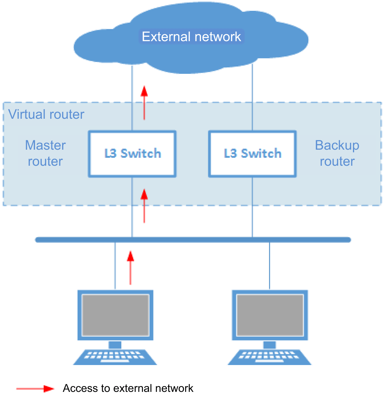
Normally, the router with the higher priority value (in the figure, the L3 switch shown on the left) serves as the master router to route the packets sent to the IP address assigned to the virtual router.
The lower priority router (the L3 switch shown on the right) waits as the backup router.
- If a Routing Problem Occurs for Master Router
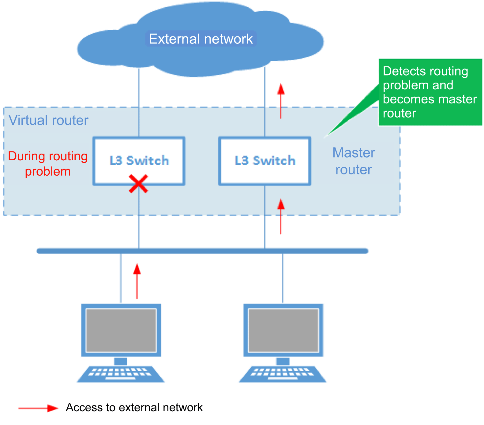
If the backup router detects a problem in the master router, it functions as the new master router.
This product only supports VRRPv3.
2 Definition of Terms Used
- Virtual Router
Router configured virtually from multiple routers by VRRP.
- Virtual IP Address
IP address assigned to a virtual router.
- Virtual MAC Address
MAC address assigned to a virtual router.
- Master Router
Router used to route packets forwarded to the virtual IP address.
- Backup Router
Router that takes over control of the virtual IP address if a routing problem occurs for the master router.
3 Function Details
This product supports the following functionality.
- Setting priority
- Setting preempt mode
- Setting circuit failover
3.1 Setting Priority
Each VRRP router is assigned a priority value. The router with the higher priority value becomes the master router and the other router the backup.
Priority values between 1 and 255 can be specified, but to ensure smooth switchover between master and backup routers, the difference between priority values should be as large as possible.
If routers have identical priority values, then the VRRP router is prioritized based on whether the IP address value is higher or lower.
Priority values are specified using the priority command.
3.2 Preempt Mode Setting
The preempt mode is a VRRP operating mode.
When the preempt mode is disabled, if a VRRP router with a lower priority becomes the master router and then later the router with the higher priority becomes available again, still the current master router will continue to serve as the master without switching to the new router. In contrast, if the preempt mode is enabled, then routing always switches to the VRRP router with the higher priority as the master router.
The preempt mode is specified using the preempt-mode command.
3.3 Circuit Failover Setting
The circuit failover setting is a function that monitors a specific VLAN interface to change the VRRP router priority level for switching the master router based on the link status of that VLAN interface.
If a link-down event in the specified VLAN interface prevents routing, then routing can be maintained by specifying the circuit failover setting.
The circuit failover setting is specified using the circuit-failover command.
4 Related Commands
Related commands are indicated below.
For details on the commands, refer to the Command Reference.
List of related commands
| Operations | Operating Commands |
|---|---|
| Switches to VRRP mode | router vrrp |
| Switches to VRRP mode (IPv6) | router ipv6 vrrp |
| Sets the interval for sending advertisement packets | advertisement-interval |
| Sets the circuit failover setting | circuit-failover |
| Enables/disables the virtual router mode | virtual-router |
| Sets the preempt mode | preempt-mode |
| Sets the virtual router priority value | priority |
| Sets the virtual IP address | virtual-ip |
| Sets the virtual IP address (IPv6) | virtual-ipv6 |
| Shows VRRP information | show vrrp |
| Shows VRRP information (IPv6) | show vrrp ipv6 |
| Shows VRRP statistical information | show vrrp statistics |
| Shows VRRP statistical information (IPv6) | show vrrp ipv6 statistics |
5 Examples of Command Execution
5.1 VRRP Settings (IPv4)
- This disables the spanning tree. If used in combination with a spanning tree, MST instance and other settings must be specified correctly.
- [Switch #A] Disable the spanning tree.
Yamaha(config)#spanning-tree shutdown
- [Switch #A] Define VLAN #100 and VLAN #200.
Yamaha(config)#vlan database Yamaha(config-vlan)#vlan 100 ... (VLAN #100 definition) Yamaha(config-vlan)#vlan 200 ... (VLAN #200 definition) Yamaha(config-vlan)#exit
- [Switch #A] Assign IP addresses for VLAN #100 and VLAN #200.
Yamaha(config)#interface vlan100 Yamaha(config-if)#ip address 192.168.100.240/24 ... (Assign 192.168.100.240 to VLAN #100) Yamaha(config-if)#exit Yamaha(config)#interface vlan200 Yamaha(config-if)#ip address 192.168.200.240/24 ... (Assign 192.168.200.240 to VLAN #200) Yamaha(config-if)#exit
- [Switch #A] Associate LAN port #1 to VLAN #100.
Yamaha(config)#interface port1.1 Yamaha(config-if)#switchport access vlan 100 ... (Associate to VLAN #100) Yamaha(config-if)#exit
- [Switch #A] Associate LAN port #2 to VLAN #200.
Yamaha(config)#interface port1.2 Yamaha(config-if)#switchport access vlan 200 ... (Associate to VLAN #200) Yamaha(config-if)#exit
- [Switch #A] Generate virtual router #1 in VLAN #100 and add settings.
Yamaha(config)#router vrrp 1 vlan100 ... (Generate virtual router #1 in VLAN #100) Yamaha(config-router)#virtual-ip 192.168.100.228 ... (Assign virtual IP address 192.168.100.228 to virtual router #1) Yamaha(config-router)#virtual-router enable ... (Enable virtual router #1) Yamaha(config-if)#exit
- [Switch #A] Generate virtual router #2 in VLAN #200 and add settings.
Yamaha(config)#router vrrp 2 vlan200 ... (Generate virtual router #2 in VLAN #200) Yamaha(config-router)#virtual-ip 192.168.200.228 ... (Assign virtual IP address 192.168.200.228 to virtual router #2) Yamaha(config-router)#virtual-router enable ... (Enable virtual router #2) Yamaha(config-if)#exit
- [Switch #B] Disable the spanning tree.
Yamaha(config)#spanning-tree shutdown
- [Switch #B] Define VLAN #100 and VLAN #200.
Yamaha(config)#vlan database Yamaha(config-vlan)#vlan 100 ... (VLAN #100 definition) Yamaha(config-vlan)#vlan 200 ... (VLAN #200 definition) Yamaha(config-vlan)#exit
- [Switch #B] Assign IP addresses for VLAN #100 and VLAN #200.
Yamaha(config)#interface vlan100 Yamaha(config-if)#ip address 192.168.100.241/24 ... (Assign 192.168.100.241 to VLAN #100) Yamaha(config-if)#exit Yamaha(config)#interface vlan200 Yamaha(config-if)#ip address 192.168.200.241/24 ... (Assign 192.168.200.241 to VLAN #200) Yamaha(config-if)#exit
- [Switch #B] Associate LAN port #1 to VLAN #100.
Yamaha(config)#interface port1.1 Yamaha(config-if)#switchport access vlan 100 ... (Associate to VLAN #100) Yamaha(config-if)#exit
- [Switch #B] Associate LAN port #2 to VLAN #200.
Yamaha(config)#interface port1.2 Yamaha(config-if)#switchport access vlan 200 ... (Associate to VLAN #200) Yamaha(config-if)#exit
- [Switch #B] Generate virtual router #1 in VLAN #100 and add settings.
Yamaha(config)#router vrrp 1 vlan100 ... (Generate virtual router #1 in VLAN #100) Yamaha(config-router)#virtual-ip 192.168.100.228 ... (Assign virtual IP address 192.168.100.228 to virtual router #1) Yamaha(config-router)#priority 50 ... (Set priority value 50 to virtual router #1) Yamaha(config-router)#virtual-router enable ... (Enable virtual router #1) Yamaha(config-if)#exit
- [Switch #B] Generate virtual router #2 in VLAN #200 and add settings.
Yamaha(config)#router vrrp 2 vlan200 ... (Generate virtual router #2 in VLAN #200) Yamaha(config-router)#virtual-ip 192.168.200.228 ... (Assign virtual IP address 192.168.200.228 to virtual router #2) Yamaha(config-router)#priority 50 ... (Set priority value 50 to virtual router #2) Yamaha(config-router)#virtual-router enable ... (Enable virtual router #2) Yamaha(config-if)#exit
- Connect the LAN cable.
- [Switch #A] Check the VRRP settings.
Yamaha#show vrrp VRRP Version: 3 VMAC enabled Backward Compatibility disabled Address family IPv4 VRRP Id: 1 on interface: vlan100 State: AdminUp - Master Virtual IP address: 192.168.100.228 (Not-owner) Operational primary IP address: 192.168.100.240 Operational master IP address: 192.168.100.240 Priority not configured; Current priority: 100 Advertisement interval: 100 centi sec Master Advertisement interval: 100 centi sec Skew time: 72 centi sec Accept mode: FALSE Preempt mode: TRUE Multicast membership on IPv4 interface vlan100: JOINED V2-Compatible: FALSE Address family IPv4 VRRP Id: 2 on interface: vlan200 State: AdminUp - Master Virtual IP address: 192.168.200.228 (Not-owner) Operational primary IP address: 192.168.200.240 Operational master IP address: 192.168.200.240 Priority not configured; Current priority: 100 Advertisement interval: 100 centi sec Master Advertisement interval: 100 centi sec Skew time: 60 centi sec Accept mode: FALSE Preempt mode: TRUE Multicast membership on IPv4 interface vlan200: JOINED V2-Compatible: FALSE
- [Switch #B] Check the VRRP settings.
Yamaha#show vrrp VRRP Version: 3 VMAC enabled Backward Compatibility disabled Address family IPv4 VRRP Id: 1 on interface: vlan100 State: AdminUp - Backup Virtual IP address: 192.168.100.228 (Not-owner) Operational primary IP address: 192.168.100.241 Operational master IP address: 192.168.100.240 Priority is 50 Advertisement interval: 100 centi sec Master Advertisement interval: 100 centi sec Skew time: 72 centi sec Accept mode: FALSE Preempt mode: TRUE Multicast membership on IPv4 interface vlan100: JOINED V2-Compatible: FALSE Address family IPv4 VRRP Id: 2 on interface: vlan200 State: AdminUp - Backup Virtual IP address: 192.168.200.228 (Not-owner) Operational primary IP address: 192.168.200.241 Operational master IP address: 192.168.200.240 Priority is 50 Advertisement interval: 100 centi sec Master Advertisement interval: 100 centi sec Skew time: 60 centi sec Accept mode: FALSE Preempt mode: TRUE Multicast membership on IPv4 interface vlan200: JOINED V2-Compatible: FALSE
5.2 VRRP Settings (IPv6)
- This disables the spanning tree. If used in combination with a spanning tree, MST instance and other settings must be specified correctly.
- [Switch #A] Disable the spanning tree.
Yamaha(config)#spanning-tree shutdown
- [Switch #A] Define VLAN #100 and VLAN #200.
Yamaha(config)#vlan database Yamaha(config-vlan)#vlan 100 ... (VLAN #100 definition) Yamaha(config-vlan)#vlan 200 ... (VLAN #200 definition) Yamaha(config-vlan)#exit
- [Switch #A] Enable IPv6 in VLAN #100.
Yamaha(config)#interface vlan100 Yamaha(config-if)#ipv6 enable ... (Enable IPv6) Yamaha(config-if)#exit
- [Switch #A] Enable IPv6 in VLAN #200.
Yamaha(config)#interface vlan200 Yamaha(config-if)#ipv6 enable ... (Enable IPv6) Yamaha(config-if)#exit
- [Switch #A] Associate LAN port #1 to VLAN #100.
Yamaha(config)#interface port1.1 Yamaha(config-if)#switchport access vlan 100 ... (Associate to VLAN #100) Yamaha(config-if)#exit
- [Switch #A] Associate LAN port #2 to VLAN #200.
Yamaha(config)#interface port1.2 Yamaha(config-if)#switchport access vlan 200 ... (Associate to VLAN #200) Yamaha(config-if)#exit
- [Switch #A] Generate virtual router #1 in VLAN #100 and add settings.
Yamaha(config)#router ipv6 vrrp 1 vlan100 ... (Generate virtual router #1 in VLAN #100) Yamaha(config-router)#virtual-ipv6 fe80::100:1 ... (Assign virtual IP address fe80::100:1 to virtual router #1) Yamaha(config-router)#virtual-router enable ... (Enable virtual router #1) Yamaha(config-if)#exit
- [Switch #A] Generate virtual router #2 in VLAN #200 and add settings.
Yamaha(config)#router ipv6 vrrp 2 vlan200 ... (Generate virtual router #2 in VLAN #200) Yamaha(config-router)#virtual-ipv6 fe80::200:1 ... (Assign virtual IP address fe80::200:1 to virtual router #2) Yamaha(config-router)#virtual-router enable ... (Enable virtual router #2) Yamaha(config-if)#exit
- [Switch #B] Disable the spanning tree.
Yamaha(config)#spanning-tree shutdown
- [Switch #B] Define VLAN #100 and VLAN #200.
Yamaha(config)#vlan database Yamaha(config-vlan)#vlan 100 ... (VLAN #100 definition) Yamaha(config-vlan)#vlan 200 ... (VLAN #200 definition) Yamaha(config-vlan)#exit
- [Switch #B] Enable IPv6 on VLAN #100.
Yamaha(config)#interface vlan100 Yamaha(config-if)#ipv6 enable ... (Enable IPv6) Yamaha(config-if)#exit
- [Switch #B] Enable IPv6 on VLAN #200.
Yamaha(config)#interface vlan200 Yamaha(config-if)#ipv6 enable ... (Enable IPv6) Yamaha(config-if)#exit
- [Switch #B] Associate LAN port #1 to VLAN #100.
Yamaha(config)#interface port1.1 Yamaha(config-if)#switchport access vlan 100 ... (Associate to VLAN #100) Yamaha(config-if)#exit
- [Switch #B] Associate LAN port #2 to VLAN #200.
Yamaha(config)#interface port1.2 Yamaha(config-if)#switchport access vlan 200 ... (Associate to VLAN #200) Yamaha(config-if)#exit
- [Switch #B] Generate virtual router #1 in VLAN #100 and add settings.
Yamaha(config)#router ipv6 vrrp 1 vlan100 ... (Generate virtual router #1 in VLAN #100) Yamaha(config-router)#virtual-ipv6 fe80::100:1 ... (Assign virtual IP address fe80::100:1 to virtual router #1) Yamaha(config-router)#priority 50 ... (Set priority value 50 to virtual router #1) Yamaha(config-router)#virtual-router enable ... (Enable virtual router #1) Yamaha(config-if)#exit
- [Switch #B] Generate virtual router #2 in VLAN #200 and add settings.
Yamaha(config)#router ipv6 vrrp 2 vlan200 ... (Generate virtual router #2 in VLAN #200) Yamaha(config-router)#virtual-ipv6 fe80::200:1 ... (Assign virtual IP address fe80::200:1 to virtual router #2) Yamaha(config-router)#priority 50 ... (Set priority value 50 to virtual router #2) Yamaha(config-router)#virtual-router enable ... (Enable virtual router #2) Yamaha(config-if)#exit
- Connect the LAN cable.
- [Switch #A] Check the VRRP settings.
Yamaha#show vrrp VRRP Version: 3 VMAC enabled Address family IPv6 VRRP Id: 1 on interface: vlan100 State: AdminUp - Master Virtual IP address: fe80::100:1 (Not-owner) Operational primary IP address: fe80::ae44:f2ff:fe11:1111 Operational master IP address: fe80::ae44:f2ff:fe11:1111 Priority is 100 Advertisement interval: 100 centi sec Master Advertisement interval: 100 centi sec Skew time: 60 centi sec Accept mode: FALSE Preempt mode: TRUE Multicast membership on IPv6 interface vlan100: JOINED V2-Compatible: FALSE Address family IPv6 VRRP Id: 2 on interface: vlan200 State: AdminUp - Master Virtual IP address: fe80::200:1 (Not-owner) Operational primary IP address: fe80::ae44:f2ff:fe11:1111 Operational master IP address: fe80::ae44:f2ff:fe11:1111 Priority is 100 Advertisement interval: 100 centi sec Master Advertisement interval: 100 centi sec Skew time: 60 centi sec Accept mode: FALSE Preempt mode: TRUE Multicast membership on IPv6 interface vlan200: JOINED V2-Compatible: FALSE
- [Switch #B] Check the VRRP settings.
Yamaha#show vrrp VRRP Version: 3 VMAC enabled Address family IPv6 VRRP Id: 1 on interface: vlan100 State: AdminUp - Backup Virtual IP address: fe80::100:1 (Not-owner) Operational primary IP address: fe80::ae44:f2ff:fe22:2222 Operational master IP address: fe80::ae44:f2ff:fe11:1111 Priority is 50 Advertisement interval: 100 centi sec Master Advertisement interval: 100 centi sec Skew time: 60 centi sec Accept mode: FALSE Preempt mode: TRUE Multicast membership on IPv6 interface vlan100: JOINED V2-Compatible: FALSE Address family IPv6 VRRP Id: 2 on interface: vlan200 State: AdminUp - Backup Virtual IP address: fe80::200:1 (Not-owner) Operational primary IP address: fe80::ae44:f2ff:fe22:2222 Operational master IP address: fe80::ae44:f2ff:fe11:1111 Priority is 50 Advertisement interval: 100 centi sec Master Advertisement interval: 100 centi sec Skew time: 60 centi sec Accept mode: FALSE Preempt mode: TRUE Multicast membership on IPv6 interface vlan200: JOINED V2-Compatible: FALSE
6 Points of Caution
- This function cannot be used in combination with the stack function.
- If both IPv4 and IPv6 are used for a VRRP, be sure different virtual router IDs are assigned.
- Do not set the secondary IP address as the virtual IP address.
7 Related Documentation
- L2 switching functions: VLAN
- SWX3220 Series Technical Data (Basic Functions)
- IP multicast functions
IGMP Snooping
1 Function Overview
IGMP snooping is a function to suppress consumption of network bandwidth in a VLAN environment, by controlling any surplus multicast flooding.
On an L2 switch, since multicast packets are distributed per VLAN, if there is even one device in the VLAN that wants to receive the multicast packet, the packet will be distributed to all ports within the same VLAN.
Operations during multicast distribution (no IGMP snooping)
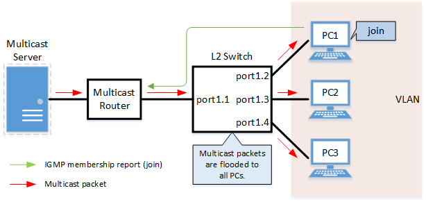
When using the IGMP snooping function, the IGMP messages exchanged between the receiving device and the multicast router are monitored (snooped), the packet from the relevant group will only be distributed to the port, to which the device that wants to receive the multicast packet is connected.
Operations during multicast distribution (using IGMP snooping)
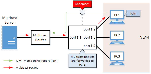
2 Definition of Terms Used
- IGMP (Internet Group Management Protocol)
This is a protocol to control multicast groups.
The multicast router can determine which hosts on the LAN are members of the multicast network, and the hosts can communicate which multicast group they belong to.
There are three protocol versions, respectively defined by IGMPv1 (RFC1112), IGMPv2 (RFC2236), and IGMPv3 (RFC3376).
- Multicast router port
This is the LAN/SFP port to which the multicast router is connected.
The LAN/SFP port that receives the IGMP general query is automatically acquired as the multicast router port.
- IGMP report control function
This is a function where the switch controls the data transmission load between the multicast router and the hosts.
The messages gathered by this product to perform control are shown below.
- IGMP reports replied to IGMP general queries by hosts, sent from the multicast router
- IGMP leave messages notified by the host
The report control function works with IGMPv1/v2/v3.
- Fast Leave function
If a LAN/SFP port receives an IGMPv2/v3 leave message, this function immediately disconnects the port from ports receiving multicast traffic (deletes the FDB entry necessary for transmission).
Normally, when processing IGMPv2/v3 messages, if a leave message is received, a group-specific query is to that port to confirm that the receiver exists, but if the fast-leave function is enabled, that action is not performed.
For this reason, the fast leave function is effective only when there is a single receiver under the control of the LAN/SFP port.
The fast-leave function operates only when an IGMPv2/v3 leave message is received.
- IGMP query transmission function (IGMP Querier)
This is a function to send IGMP general and specific queries.
It is used to make IGMP snooping function in an environment without a multicast router.
- Data Forwarding to Multicast Router Port Control Function
This function controls multicast data being forwarded to the multicast router port.
Normally, all multicast group data already acquired by the product is forwarded to the multicast router port, but if this function is enabled, then only multicast group data acquired by receiving an IGMP report via the multicast router port is forwarded.
If unnecessary multicast data flow between switches is restricting bandwidth, the problem can be mitigated by enabling this function in combination with the l2-unknown-mcast discard command.
3 Function Details
The operating specifications for IGMP snooping are shown below.
- This product offers snooping functions compatible with IGMP v1/v2/v3.
You can use the ip igmp snooping version command to make later versions operate on this product.
Version settings are made for the VLAN interface, and initial settings are for v3.
The difference in operations between the configured version and received frame versions are shown in the table below.
- If an IGMP query whose version is higher than the settings is received, the configured version will be lowered, and the query will be forwarded.
- If an IGMP report whose version is higher than the specified version is received, the relevant report will be discarded without being forwarded.
- If an IGMP query and report of a lower version than the specified version is received, it is forwarded unmodified as the received version.
- The settings to enable/disable IGMP snooping are made for the VLAN interface.
The default value is enabled.
- The IGMP snooping function can handle the following five operations.
- Multicast router port setting
- IGMP report control
- Fast-leave
- IGMP query transmission
- Data Forwarding to Multicast Router Port Control
- Although the multicast router port is automatically acquired on VLAN interfaces where IGMP snooping is set to “enable”, the ip igmp snooping mrouter interface command can also be used to make static settings.
The show ip igmp snooping mrouter command is used to check multicast router ports that are set for the VLAN interface.
- The IGMP report control function is specified using the ip igmp snooping report-suppression command for VLAN interfaces.
The default value is enabled.
When transmitting an IGMP report or IGMP leave message using the report control function, the IPv4 address allocated to the VLAN interface will be used for the source IPv4 address.
(The address will be set and transmitted as “0.0.0.0” if it has not been allocated.)
- The fast-leave function is set for the VLAN interface using the ip igmp snooping fast-leave command.
The default value is disabled.
- The IGMP query transmission function is supported in order to allow use of IGMP snooping in environments that do not have a multicast router.
The IGMP query transmission function controls the following two parameters.
- IGMP query transmission function Enable/disable
- The ip igmp snooping querier command is used for VLAN interfaces.
- The default value is disabled.
- IGMP query transmission interval
- This is executed using the ip igmp snooping query-interval command.
- The transmission interval can be set from 20–18,000 sec., and the default value is 125 sec.
- IGMP query transmission function Enable/disable
- When multiple devices transmit queries within a VLAN, the query is sent by the device with the lowest IPv4 address within the VLAN.
When this product receives a query from a device whose IPv4 address is lower than its own, the query transmission function will be halted.
The source iPv4 address that is set when a query is transmitted uses the IPv4 address allocated to the VLAN interface. If an IPv4 address has not been allocated, an IPv4 address allocated to a different VLAN interface is used instead.
(If no IPv4 addresses have been allocated to any VLAN interfaces, the address will be set and transmitted as “0.0.0.0”.)
- This product features a function that forces the TTL value of a received IGMP packet to change to “1” if the TTL value is invalid (a value other than “1”), instead of discarding the packet.
This is defined as the “TTL check function”, and it can be configured for a VLAN interface by using the ip igmp snooping check ttl command.
The default setting value for the TTL check function is enabled (packets with invalid TTL values are discarded).
- The data forwarding to multicast router port control function is specified for VLAN interfaces using the ip igmp snooping mrouter-port data-suppression command.
The default value is disabled.
4 Related Commands
The related commands are shown below.
For details on the commands, refer to the Command Reference.
List of related commands
| Operations | Operating Commands |
|---|---|
| Enable/disable IGMP snooping | ip igmp snooping |
| Set IGMP snooping fast-leave | ip igmp snooping fast-leave |
| Set multicast router port | ip igmp snooping mrouter interface |
| Set query transmission function | ip igmp snooping querier |
| Set IGMP query transmission interval | ip igmp snooping query-interval |
| Set IGMP snooping TTL check | ip igmp snooping check ttl |
| Set IGMP version | ip igmp snooping version |
| Setting the IGMP Report Control Function | ip igmp snooping report-suppression |
| Setting the Data Forwarding to Multicast Router Port Control Function | ip igmp snooping mrouter-port data-suppression |
| Show multicast router port information | show ip igmp snooping mrouter |
| Show IGMP multicast recipient information | show ip igmp snooping groups |
| Show an interface’s IGMP-related information | show ip igmp snooping interface |
| Clear IGMP group membership entries | clear ip igmp snooping |
5 Examples of Command Execution
5.1 IGMP snooping settings (with multicast router)
In an environment with a multicast router, enable the IGMP snooping function and join a multicast group.
Data is distributed only to PC1 and PC3.
IGMP snooping setting example (with multicast router)
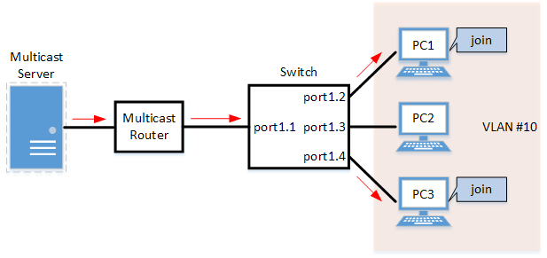
- LAN ports #1–#4 are set as access ports, and associated with VLAN #10.
- Since there is a multicast router, the IGMP query transmission function is left as “disabled”.
- Multicast router port acquisition is set to automatic acquisition only. (A static setting is not used.)
- The fast-leave function is enabled.
- Define VLAN #10, and set IGMP snooping.
Yamaha(config)# vlan database Yamaha(config-vlan)#vlan 10 ... (VLAN #10 definition) Yamaha(config-vlan)#exit Yamaha(config)#interface vlan10 Yamaha(config-if)#ip igmp snooping enable ... (Enable IGMP Snooping for VLAN #10) Yamaha(config-if)#no ip igmp snooping querier ... (Disable IGMP query transmission function for VLAN #10) Yamaha(config-if)#ip igmp snooping fast-leave ... (Enable IGMP Fast-leave function for VLAN #10)
- By default, IGMP snooping is enabled and IGMP query transmission is disabled, so there is no need to set them.
- Set LAN ports #1–#4 as access ports, and associate them with VLAN #10.
Yamaha(config)# interface port1.1 Yamaha(config-if)# switchport mode access Yamaha(config-if)# switchport access vlan 10 (Also perform the above settings for LAN ports #2-#4.)
- Confirm the multicast router port information. (It should be connected to LAN port #1.)
Yamaha#show ip igmp snooping mrouter vlan10 VLAN Interface IP-address Expires 10 port1.1(dynamic) 192.168.100.216 00:00:49
- Confirm the information for the multicast recipient.
Yamaha#show ip igmp snooping groups IGMP Snooping Group Membership Group source list: (R - Remote, S - Static) Vlan Group/Source Address Interface Flags Uptime Expires Last Reporter Version 10 239.0.0.1 port1.2 R 00:00:13 00:00:41 192.168.100.2 V3 10 239.0.0.1 port1.4 R 00:00:02 00:00:48 192.168.100.4 V3
5.2 IGMP snooping settings (without multicast router)
In an environment without a multicast router, enable the IGMP snooping function and join a multicast group.
Data is distributed only to PC1 and PC3.
IGMP snooping settings (without multicast router)
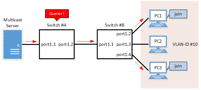
- Switch #A
- LAN ports #1–#2 are set as access ports, and associated with VLAN #10.
- The IGMP query transmission function is enabled.
The IGMP query transmission interval is set to 20 sec.
- Switch #B
- LAN ports #1–#4 are set as access ports, and associated with VLAN #10.
- Multicast router port acquisition is set to automatic acquisition only. (A static setting is not used.)
- The Fast-Leave function is enabled.
- Since there is a device that sets invalid TTL values in IGMP packets, disable the TTL check function.
- [Switch #A] Define VLAN #10, and set IGMP snooping.
Yamaha(config)# vlan database Yamaha(config-vlan)#vlan 10 ... (VLAN #10 definition) Yamaha(config-vlan)#exit Yamaha(config)#interface vlan10 Yamaha(config-if)#ip igmp snooping enable ... (Enable IGMP Snooping for VLAN #10) Yamaha(config-if)#ip igmp snooping querier ... (Enable IGMP query transmission function for VLAN #10) Yamaha(config-if)#ip igmp snooping query-interval 20 ... (Set 20 seconds as the IGMP query transmission interval for VLAN #10)
- Since IGMP snooping is enabled by default, we do not need to set this specifically.
- [Switch #A] Set LAN ports #1–#2 as access ports, and associate them with VLAN #10.
Yamaha(config)# interface port1.1 Yamaha(config-if)# switchport mode access Yamaha(config-if)# switchport access vlan 10 (Also perform the above settings for LAN port #2.)
- [Switch #B] Define VLAN #10, and set IGMP snooping.
Yamaha(config)# vlan database Yamaha(config-vlan)#vlan 10 ... (VLAN #10 definition) Yamaha(config-vlan)#exit Yamaha(config)#interface vlan10 Yamaha(config-if)#ip igmp snooping enable ... (Enable IGMP Snooping for VLAN #10) Yamaha(config-if)#no ip igmp snooping querier ... (Disable IGMP query transmission function for VLAN #10) Yamaha(config-if)#no ip igmp snooping check ttl ... (Disable TTL check function for VLAN #10) Yamaha(config-if)#ip igmp snooping fast-leave ... (Enable IGMP Fast-leave function for VLAN #10)
- By default, IGMP snooping is enabled and IGMP query transmission is disabled, so there is no need to set them.
- [Switch #B] Set LAN ports #1–#4 as access ports, and associate them with VLAN #10.
Yamaha(config)# interface port1.1 Yamaha(config-if)# switchport mode access Yamaha(config-if)# switchport access vlan 10 (Also perform the above settings for LAN ports #2-#4.)
- [Switch #B] Confirm the information for the multicast recipient. (It should be connected to LAN port #1.)
Yamaha#show ip igmp snooping mrouter vlan10 VLAN Interface IP-address Expires 10 port1.1(dynamic) 192.168.100.216 00:00:49
- [Switch #B] Confirm the information for the multicast recipient.
Yamaha#show ip igmp snooping groups IGMP Snooping Group Membership Group source list: (R - Remote, S - Static) Vlan Group/Source Address Interface Flags Uptime Expires Last Reporter Version 10 239.0.0.1 port1.2 R 00:00:13 00:00:41 192.168.100.2 V3 10 239.0.0.1 port1.4 R 00:00:02 00:00:48 192.168.100.4 V3
5.3 IGMP Snooping Setting (If Distributing Data in Both Directions)
In a configuration with two switches, both switches are connected to a multicast server and computer.
Each computer frequently switches between participating multicast groups to minimize the interruption time.
- IGMP Snooping Setting Example (If Distributing Data in Both Directions)
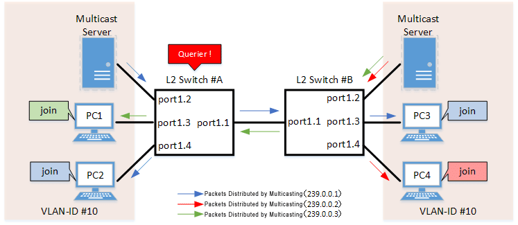
- Switch #A
- Sets LAN ports #1–#4 as access ports and associates them with VLAN #10.
- The IGMP query transmission function is enabled.
Sets the IGMP query transmission interval value to 20 sec.
- The Fast-Leave function is enabled.
- The IGMP report control function is disabled.
- Increasing the number of multicast servers or data distributions could cause port bandwidth restrictions, so the data forwarding to multicast router port control function is enabled to only forward the minimum data necessary.
It also discards unknown multicast frames.
- LAN port #1 is set as a static multicast router port for forwarding IGMP reports to non-queriers.
- Switch #B
- Sets LAN ports #1–#4 as access ports and associates them with VLAN #10.
- Multicast router port acquisition is set to automatic acquisition only. (A static setting is not used.)
- The Fast-Leave function is enabled.
- The IGMP report control function is disabled.
- Increasing the number of multicast servers or data distributions could cause port bandwidth restrictions, so the data forwarding to multicast router port control function is enabled to only forward the minimum data necessary.
It also discards unknown multicast frames.
- [Switch #A] Define VLAN #10 and specify IGMP snooping.
Yamaha(config)# vlan database Yamaha(config-vlan)#vlan 10 ... (Defines VLAN #10) Yamaha(config-vlan)#exit Yamaha(config)#interface vlan10 Yamaha(config-if)#ip igmp snooping enable ... (Enables IGMP snooping for VLAN #10) Yamaha(config-if)#ip igmp snooping querier ... (Enables the IGMP query transmission function for VLAN #10) Yamaha(config-if)#ip igmp snooping query-interval 20 ... (Sets the IGMP query transmission interval to 20 seconds for VLAN #10) Yamaha(config-if)#ip igmp snooping fast-leave ... (Enables the fast-leave function for VLAN #10) Yamaha(config-if)#ip igmp snooping report-suppression disable ... (Disables the report control function for VLAN #10) Yamaha(config-if)#ip igmp snooping mrouter-port data-suppression enable ... (Enables the data forwarding to multicast router port control function for VLAN #10) Yamaha(config-if)#ip igmp snooping mrouter interface port1.1 ... (Sets LAN port #1 as the multicast router port for VLAN #10)
- IGMP snooping does not need to be specified because it is enabled by default.
- [Switch #A] Set LAN ports #1–#4 as access ports and associate them with VLAN #10.
Yamaha(config)# interface port1.1 Yamaha(config-if)# switchport mode access Yamaha(config-if)# switchport access vlan 10 (Configures the settings above for LAN ports #2–#4 as well.)
- [Switch #A] Discard unknown multicast frames.
Yamaha(config)#l2-unknown-mcast discard
- [Switch #B] Define VLAN #10 and specify IGMP snooping.
Yamaha(config)# vlan database Yamaha(config-vlan)#vlan 10 ... (Defines VLAN #10) Yamaha(config-vlan)#exit Yamaha(config)#interface vlan10 Yamaha(config-if)#ip igmp snooping enable ... (Enables IGMP snooping for VLAN #10) Yamaha(config-if)#no ip igmp snooping querier ... (Disables the IGMP query transmission function for VLAN #10) Yamaha(config-if)#ip igmp snooping fast-leave ... (Enables the fast-leave function for VLAN #10) Yamaha(config-if)#ip igmp snooping report-suppression disable ... (Disables the report control function for VLAN #10) Yamaha(config-if)#ip igmp snooping mrouter-port data-suppression enable ... (Enables the data forwarding to multicast router port control function for VLAN #10)
- IGMP snooping is enabled and IGMP query transmission is disabled in default settings, so there is no need to specify those settings.
- [Switch #B] Set LAN ports #1–#4 as access ports, and associate them with VLAN #10.
Yamaha(config)# interface port1.1 Yamaha(config-if)# switchport mode access Yamaha(config-if)# switchport access vlan 10 (Configures the settings above for LAN ports #2–#4 as well.)
- [Switch #B] Discard unknown multicast frames.
Yamaha(config)#l2-unknown-mcast discard
- [Switch #A] Check the multicast router port information. (Connected to LAN port #1)
Yamaha#show ip igmp snooping mrouter vlan10 VLAN Interface IP-address Expires 10 port1.1(static) -- --
- [Switch #A] Check the multicast receiver information.
Yamaha#show ip igmp snooping groups IGMP Snooping Group Membership Group source list: (R - Remote, S - Static) Vlan Group/Source Address Interface Flags Uptime Expires Last Reporter Version 10 239.0.0.1 port1.1 R 00:00:02 00:00:48 192.168.100.3 V3 10 239.0.0.2 port1.1 R 00:00:02 00:00:48 192.168.100.4 V3 10 239.0.0.3 port1.3 R 00:00:04 00:00:46 192.168.100.1 V3 10 239.0.0.1 port1.4 R 00:00:03 00:00:47 192.168.100.2 V3
- [Switch #B] Check the multicast router port information. (Connected to LAN port #1)
Yamaha#show ip igmp snooping mrouter vlan10 VLAN Interface IP-address Expires 10 port1.1(dynamic) 192.168.100.240 00:00:25
- [Switch #B] Check the multicast receiver information.
Yamaha#show ip igmp snooping groups IGMP Snooping Group Membership Group source list: (R - Remote, S - Static) Vlan Group/Source Address Interface Flags Uptime Expires Last Reporter Version 10 239.0.0.1 port1.1 R 00:00:03 00:00:47 192.168.100.2 V3 10 239.0.0.3 port1.1 R 00:00:04 00:00:46 192.168.100.1 V3 10 239.0.0.1 port1.3 R 00:00:02 00:00:48 192.168.100.3 V3 10 239.0.0.2 port1.4 R 00:00:02 00:00:48 192.168.100.4 V3
6 Points of Caution
To change how unknown multicast frames are processed, use the l2-unknown-mcast command to specify settings.
To exclude specific multicast addresses from unknown multicast frames, specify the l2-unknown-mcast forward command.
When a topology change is detected, if you want to send a query regardless of the normal transmission interval, set the l2-mcast snooping tcn-query command.
7 Related Documentation
- L2 switching functions: VLAN
MLD Snooping
1 Function Overview
MLD snooping is a function to suppress consumption of network bandwidth in an IPv6 VLAN environment, by controlling any surplus multicast flooding.
On an L2 switch, since multicast packets are distributed per VLAN, if there is even one device in the VLAN that wants to receive the multicast packet, the packet will be distributed to all ports within the same VLAN.
Operations during multicast distribution (no MLD snooping)
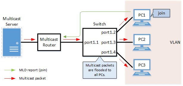
When using the MLD snooping function, the MLD messages exchanged between the receiving device and the multicast router are monitored (snooped), and the packet from the relevant group will only be distributed to the port, to which the device that wants to receive the multicast packet is connected.
Operations during multicast distribution (using MLD snooping)

2 Definition of Terms Used
- MLD (Multicast Listener Discovery)
This is a protocol to control multicast groups using IPv6 (a sub-protocol of ICMPv6).
The multicast router can determine which hosts on the LAN are members of the multicast network, and the hosts can communicate which multicast group they belong to.
There are two protocol versions, respectively defined by , MLDv1 (RFC2710), and MLDv2 (RFC3810).
- Multicast router port
This is the LAN/SFP port to which the multicast router is connected.
The LAN/SFP port that receives the MLD general query is automatically acquired as the multicast router port.
- MLD report control function
This is a function where the L2 switch controls the data transmission load between the multicast router and the hosts.
The messages gathered by this product to perform control are shown below.
- MLD reports replied to MLD general queries by hosts, sent from the multicast router
- MLD Done messages notified by the host and MLD reports (Leave)
The report control function works with MLDv1/v2.
- MLD Fast Leave function
This function allows for the LAN/SFP port that received an MLDv1 Done and an MLDv2 report (Leave) to immediately stop receiving multicasts (deleting the necessary FDB entry).
Previously, when an MLDv1 Done message and an MLDv2 report (Leave) was received in the course of MLD leave processing, a group-specific query was sent to check for the existence of a receiver; but if the fast-leave function is enabled, this operation is not performed.
For this reason, the fast leave function is effective only when there is a single receiver under the control of the LAN/SFP port.
- MLD query transmission function (MLD Querier)
This is a function to send MLD general and specific queries.
It is used to make the MLD snooping function in an environment without a multicast router.
3 Function Details
The operating specifications for MLD snooping are shown below.
- This product offers snooping functions compatible with MLDv1/v2.
You can use the mld snooping version command to make later versions work on this product.
Version settings are made for the VLAN interface, and initial settings are for v2.
The difference in operations between the configured version and received frame versions are shown in the table below.- If an MLD query whose version is higher than the settings is received, the version will be lowered to the version that was configured, and the query will be forwarded.
- If an MLD report whose version is higher than the configured version is received, the relevant report will be discarded without being forwarded.
- The settings to enable/disable MLD snooping are made for the VLAN interface.
The initial setting for the default VLAN (VLAN #1) and the initial setting after a VLAN is generated are both enabled.
- The MLD snooping function can handle the following four operations.
- Multicast router port setting
- MLD report control
- MLD fast leave
- MLD query transmission
- Although the multicast router port is automatically acquired on VLAN interfaces where MLD snooping is set to "enable”, the mld snooping mrouter interface command can also be used to make static settings.
The show mld snooping mrouter command is used to check multicast router ports that are set for the VLAN interface.
- The MLD report control function is automatically enabled on VLAN interfaces for which MLD snooping has been set to “enable”.
The MLD report control function cannot be disabled.
When transmitting an MLD report or MLD Done message using the report control function, the IPv6 link local address allocated to the VLAN interface will be used for the source IPv6 address.
(The address will be set and transmitted as “::” if it has not been allocated.)
- The MLD fast-leave function is set for the VLAN interface using the mld snooping fast-leave command.
The initial setting for the default VLAN (VLAN #1) and the initial setting after a VLAN is generated are both disabled.
- The MLD query transmission function is supported in order to allow use of MLD snooping in environments that do not have a multicast router.
The MLD query transmission function controls the following two parameters.- MLD query transmission function enable/disable
- The mld snooping querier command is used for VLAN interfaces.
- The initial setting for the default VLAN (VLAN #1) and the initial setting after a VLAN is generated are both disabled.
- MLD query transmission interval
- This is set using the mld snooping query-interval command.
- The transmission interval can be set from 20–18,000 sec., and the default value is 125 sec.
- MLD query transmission function enable/disable
- When multiple devices transmit queries within a VLAN, the query is sent by the device with the lowest IPv6 address within the VLAN.
When this product receives a query from a device whose IPv6 address is lower than its own, the query transmission function will be halted.
The source iPv6 address that is set when a query is transmitted uses the IPv6 link local address allocated to the VLAN interface. If an IPv6 link local address has not been allocated, an IPv6 link local address allocated to a different VLAN interface is used instead.
(If no IPv6 link local addresses have been allocated to any VLAN interfaces, the query is not transmitted.)
4 Related Commands
Related commands are shown below.
For details on the commands, refer to the Command Reference.
List of related commands
| Operations | Operating Commands |
|---|---|
| Enable/disable MLD snooping | ipv6 mld snooping |
| Set MLD snooping fast-leave | ipv6 mld snooping fast-leave |
| Set the multicast router port | ipv6 mld snooping mrouter interface |
| Set query transmission function | ipv6 mld snooping querier |
| Set the MLD query transmission interval | ipv6 mld snooping query-interval |
| Set the MLD version | ipv6 mld snooping version |
| Show multicast router port information | show ipv6 mld snooping mrouter |
| Show MLD multicast recipient information | show ipv6 mld snooping groups |
| Show an interface’s MLD-related information | show ipv6 mld snooping interface |
| Clear the MLD group membership entries | clear ipv6 mld snooping |
5 Examples of Command Execution
5.1 MLD snooping settings (with multicast router)
In an environment with a multicast router, this enables the MLD snooping function, and data is distributed only to PC1 and PC3 which are joined to a multicast group.
MLD snooping setting example (with multicast router)

- LAN ports #1–#4 are set as access ports, and associated with VLAN #10.
- Since there is a multicast router, the MLD query transmission function is left as “disabled”.
- Multicast router port acquisition is set to automatic acquisition only. (A static setting is not used.)
- The MLD fast-leave function is enabled.
- Define VLAN #10, and set MLD snooping.
Yamaha(config)# vlan database Yamaha(config-vlan)#vlan 10 ... (definition of VLAN #10) Yamaha(config-vlan)#exit Yamaha(config)#interface vlan10 Yamaha(config-if)#ipv6 enable ... (enables IPv6 functionality on VLAN #10) Yamaha(config-if)#ipv6 mld snooping ... (enables MLD Snooping on VLAN #10) Yamaha(config-if)#no ipv6 mld snooping querier ... (disables the MLD query transmission function on VLAN #10) Yamaha(config-if)#ipv6 mld snooping fast-leave ... (enables the MLD Fast-leave function on VLAN #10)
- By default, MLD snooping is enabled and MLD query transmission is disabled, so there is no need to set them.
- Set LAN ports #1–#4 as access ports, and associate them with VLAN #10.
Yamaha(config)# interface port1.1 Yamaha(config-if)# switchport mode access Yamaha(config-if)# switchport access vlan 10 (the settings above are also applied to LAN ports #2–#4)
- Confirm the multicast router port information. (It should be connected to LAN port #1.)
Yamaha#show ipv6 mld snooping mrouter vlan10 VLAN Interface IP-address Expires 10 port1.1(dynamic) fe80::2a0:deff:feae:b879 00:00:43
- Confirm the information for the multicast recipient.
Yamaha#show ipv6 mld snooping groups MLD Connected Group Membership Vlan Group Address Interface Uptime Expires Last Reporter 10 ff15::1 port1.2 00:00:13 00:00:41 fe80::a00:27ff:fe8b:87e2 10 ff15::1 port1.4 00:00:02 00:00:48 fe80::a00:27ff:fe8b:87e4
5.2 MLD snooping settings (without multicast router)
In an environment without a multicast router, this enables the MLD snooping function, and data is distributed only to PC1 and PC3 which are joined to a multicast group.
MLD snooping settings (without multicast router)

- Switch #A
- LAN ports #1–#2 are set as access ports, and associated with VLAN #10.
- The MLD query transmission function is enabled.
The MLD query transmission interval is set to 20 sec.
- Switch #B
- LAN ports #1–#4 are set as access ports, and associated with VLAN #10.
- Multicast router port acquisition is set to automatic acquisition only. (A static setting is not used.)
- The MLD fast-leave function is enabled.
- [Switch #A] Define VLAN #10, and set MLD snooping.
Yamaha(config)# vlan database Yamaha(config-vlan)#vlan 10 ... (definition of VLAN #10) Yamaha(config-vlan)#exit Yamaha(config)#interface vlan10 Yamaha(config-if)#ipv6 enable ... (enables IPv6 functionality on VLAN #10) Yamaha(config-if)#ipv6 mld snooping ... (enables MLD Snooping on VLAN #10) Yamaha(config-if)#ipv6 mld snooping querier ... (enables the MLD query transmission function on VLAN #10) Yamaha(config-if)#ipv6 mld snooping query-interval 20 ... (sets the MLD query transmission interval to 20 sec. on VLAN #10)
- Since MLD snooping is enabled by default, we do not need to set this specifically.
- [Switch #A] Set LAN ports #1–#2 as access ports, and associate them with VLAN #10.
Yamaha(config)# interface port1.1 Yamaha(config-if)# switchport mode access Yamaha(config-if)# switchport access vlan 10 (the settings above are also applied to LAN port #2)
- [Switch #B] Define VLAN #10, and set MLD snooping.
Yamaha(config)# vlan database Yamaha(config-vlan)#vlan 10 ... (definition of VLAN #10) Yamaha(config-vlan)#exit Yamaha(config)#interface vlan10 Yamaha(config-if)#ipv6 enable ... (enables IPv6 functionality on VLAN #10) Yamaha(config-if)#ipv6 mld snooping ... (enables MLD Snooping on VLAN #10) Yamaha(config-if)#no ipv6 mld snooping querier ... (disables the MLD query transmission function on VLAN #10) Yamaha(config-if)#ipv6 mld snooping fast-leave ... (enables the MLD Fast-leave function on VLAN #10)
- By default, MLD snooping is enabled and MLD query transmission is disabled, so there is no need to set them.
- [Switch #B] Set LAN ports #1–#4 as access ports, and associate them with VLAN #10.
Yamaha(config)# interface port1.1 Yamaha(config-if)# switchport mode access Yamaha(config-if)# switchport access vlan 10 (the settings above are also applied to LAN ports #2–4)
- [Switch #B] Confirm the information for the multicast recipient. (It should be connected to LAN port #1.)
Yamaha#show ipv6 mld snooping mrouter vlan10 VLAN Interface IP-address Expires 10 port1.1(dynamic) fe80::2a0:deff:feae:b879 00:00:43
- [Switch #B] Confirm the information for the multicast recipient.
Yamaha#show ipv6 mld snooping groups MLD Connected Group Membership Vlan Group Address Interface Uptime Expires Last Reporter 10 ff15::1 port1.2 00:00:13 00:00:41 fe80::a00:27ff:fe8b:87e2 10 ff15::1 port1.4 00:00:02 00:00:48 fe80::a00:27ff:fe8b:87e4
6 Points of Caution
If you want to change the handling of unknown multicast frames, use the l2-unknown-mcast command.
When a topology change is detected, if you want to send a query regardless of the normal transmission interval, set the l2-mcast snooping tcn-query command.
If the stack function is enabled, this will be disabled regardless of the MLD snooping settings.
7 Related Documentation
- Layer 2 functions: VLAN
- Layer 3 functions: IPv6 basic settings
IGMP
1 Function Overview
Multicasting is used to broadcast multiple audio or video streams to multiple terminals by copying each IP packet and sending them to multiple specified recipients (multicast receivers).
Data streaming by multicasting can help minimize server and bandwidth loads because the server sending the multicast only needs to send one packet.
The Internet Group Management Protocol (IGMP) is a protocol for determining which multicast receivers on a LAN have joined respective multicast groups by notifying the multicast routers used by multicast receivers when each router joins, remains in, or leaves a multicast group. IGMP is generally used in combination with a multicasting routing protocol such as Protocol Independent Multicast (PIM), so that the multicast router controls forwarding of multicast packets based on information notified from multicast receivers by IGMP.
Using an L2 switch, the multicast packets are flooded to all ports within the VLAN, but the IGMP Snooping function can be used to send respective group packets only to ports connected to a terminal that wants to receive the multicast packets.
IGMP actions are illustrated in the figure below. Multicasting traffic is routed within the multicast network using a multicasting protocol such as PIM.
When a multicast router connected to a multicast receiver receives a request from the multicast receiver to join a multicast group, the multicast traffic is forwarded to the VLAN interface associated with that multicast receiver.
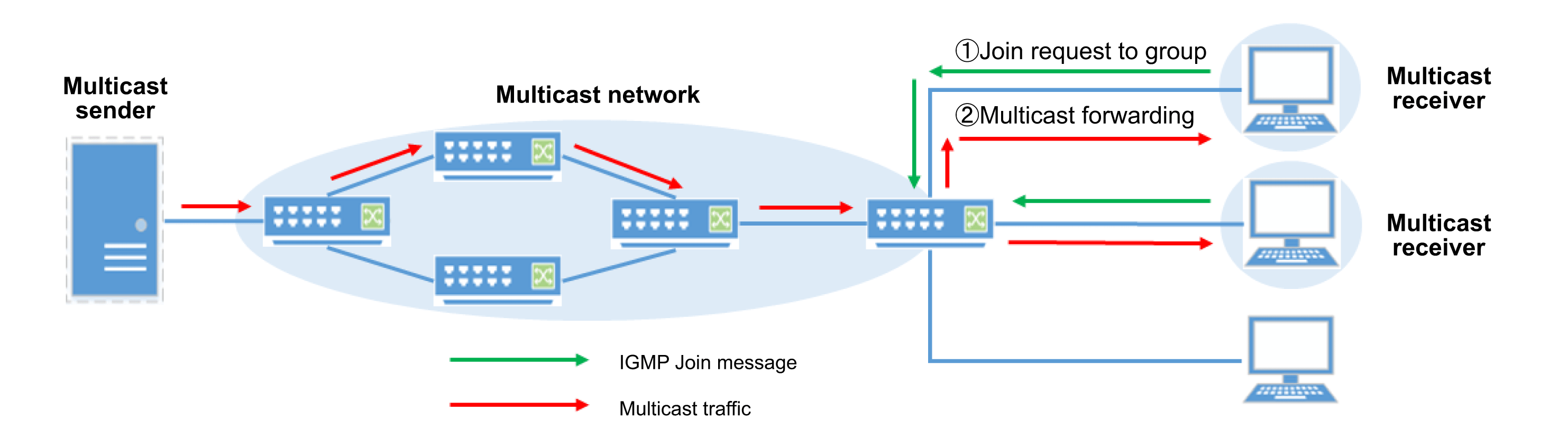
The actions of the IGMP proxy function are illustrated below. By using the IGMP Proxy function, IGMP messages can be relayed without enabling a multicasting routing protocol such as PIM.
This proxy function can relay multicast packets streamed from upstream multicast routers to downstream multicast receivers.
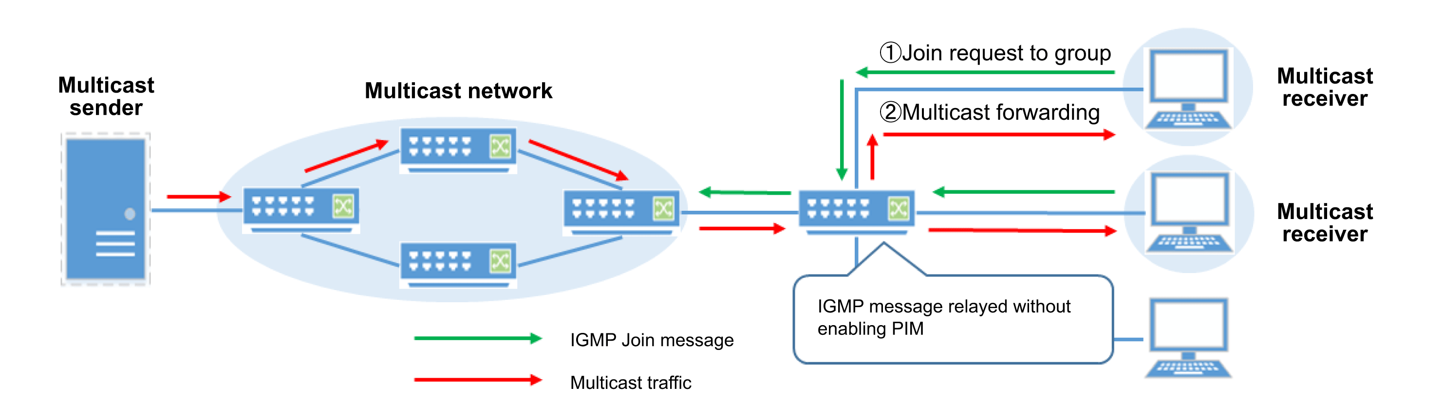
2 Definition of Terms Used
- IGMP (Internet Group Management Protocol)
This is a protocol to control multicast groups.
The multicast router can determine which hosts on the LAN are members of the multicast network, and the hosts can communicate which multicast group they belong to.
There are three protocol versions, respectively defined by IGMPv1 (RFC1112), IGMPv2 (RFC2236) and IGMPv3 (RFC3376). This product supports IGMPv2 and IGMPv3.
- Upstream Interface
This is the interface where the multicast sender is located.
- Downstream Interface
This is the interface where the multicast receiver is located.
- Source Specific Multicast (SSM) Mapping
By associating the sending address of the multicast sender with the multicast group, the function can receive only multicast traffic from specific senders, even if the host only supports IGMPv1 or IGMPv2.
3 Function Details
The IGMP operating specifications are indicated below.
Basic IGMP Settings
- The IGMP enable/disable setting is compatible with VLAN interfaces.
The initial setting is disabled for both the default VLAN (VLAN #1) and after a VLAN is generated.
IGMP can be enabled using the ip igmp command. Also, if PIM is enabled, then IGMP is automatically enabled as well.
To enable IGMP, use the ip multicast-routing command to enable the IP Multicast Routing function (disabled in default settings) for the entire system.
Use the multicast command to enable the Multicast Routing function (enabled in default settings) for each port.
- This product supports both IGMPv2 and v3, with the ip igmp version command used to switch between IGMP versions.
The version is set to IGMPv3 in default settings.
Joining, Remaining in, or Leaving Multicast Groups
- A multicast router with IGMP enabled becomes a querier that periodically sends a general query to confirm whether any multicast receivers are present.
When the multicast receiver receives the general query, they communicate their interest in joining the multicast group by sending a Report message.
Report messages are sometimes sent intentionally by the multicast receiver. When a multicast router receives the Report, it forwards multicast traffic to the VLAN interface associated with the multicast receiver location.
The interval between sending general queries is specified using the ip igmp query-interval command.
The maximum response time to general queries is set using the ip igmp query-max-response-time command.
- Multicast receivers that have joined a multicast group can leave the group by sending a Leave message (if using IGMPv2) or a Report that includes information for leaving (if using IGMPv3).
When the multicast router receives the Leave message from a multicast receiver, it sends a group-specific query multiple times to confirm that there are no other multicast receivers in that group.
This product floods all ports on the same VLAN with the group-specific query.
If there is no response to the group-specific query, then it decides there are no multicast receivers in that group and deletes the IGMP group membership entry.
The interval between sending the group-specific queries is specified using the ip igmp last-member-query-interval command.
The number of group-specific queries to send is specified using the ip igmp last-member-query-count command.
- If there are multiple queries present on the same VLAN, the multicast router with the smallest IP address becomes the querier and the other queries stop sending queries.
If no query is received from a querier for any reason, another multicast router will take over the role of querier.
The wait time before another querier takes over after a querier stops sending queries is specified using the ip igmp querier-timeout command.
However, in network environments prone to packet loss, due to congestion or other factors, robustness can be increased with respect to packet loss by setting a larger ip igmp robustness-variable command setting value.
- With IGMPv2, an Immediate-Leave function can be used to delete the IGMP group membership entry immediately after sending the Leave message.
If another multicast receiver is present on the same VLAN, deleting the IGMP group membership entry will prevent forwarding multicast traffic, so do not enable the Immediate-Leave function.
The Immediate-Leave function is initially disabled for both the default VLAN (VLAN #1) and after a VLAN is generated.
The Immediate-Leave function is set using the ip igmp immediate-leave command.
- For Report/Leave messages, the sending address is checked by default and if the sending address and interface are associated with different subnet address ranges, then it is discarded.
To allow receiving IGMP messages from different subnets, use the ip igmp check source-address disable command.
However, if the sending address is 0.0.0.0, the message is received regardless of the ip igmp check source-address setting.
- Multicast receivers that can join a multicast group can be restricted using an IPv4 access list.
Multicast receivers can be restricted using the ip igmp access-group command.
- The maximum number of people that can be registered in an IGMP group can be changed using the ip igmp limit command.
- The ip igmp static-group command is used to add IGMP group membership entries statically to the VLAN interface.
Adding a static entry results in the system always assuming a multicast receiver is present on the applicable VLAN interface, so that multicast traffic is forwarded to that VLAN.
Nevertheless, the actual system does not receive multicast traffic or send Report messages.
- Dynamically registered IGMP group membership entries can be deleted using the clear ip igmp command.
However, entries added statically using the ip igmp static-group cannot be deleted.
- IGMP group membership information can be checked using the show ip igmp groups command.
- Use the show ip igmp interface command to check information for VLAN interfaces where IGMP is enabled.
SSM Mapping Function
Though IGMPv3 allows specifying a multicast sender in Report information to receive multicast traffic only from specific multicast senders, multicast senders cannot be specified in IGMPv2.
By using the SSM (source specific multicast) Mapping function to map multicast senders to specific multicast groups, even multicast receivers using IGMPv2 can receive only multicast traffic from specific multicast senders.
The SSM Mapping function is enabled in default settings.
Use the ip igmp ssm-map command to enable/disable the SSM Mapping function.
Use the ip igmp ssm-map static command to map multicast groups to multicast senders. In this product, an entire multicast group can be used as the SSM range, rather than only the standard SSM range (232.0.0.0/8).
IGMP Proxy Function
By using the IGMP Proxy function, multicast traffic received from higher-level multicast routers can be forwarded to multicast receivers without using a multicast routing protocol.
The IGMP Proxy function requires specifying the upstream interface (where the multicast sender is located) and the downstream interface (where the multicast receiver is located).
Use the ip igmp proxy-service command to specify the upstream interface setting for the IGMP Proxy function.
Use the ip igmp mroute-service command to specify the downstream interface setting for the IGMP Proxy function.
Multiple downstream interfaces can be specified for each upstream interface.
However, PIM and other multicast routing protocols cannot be enabled for interfaces using the IGMP Proxy function.
4 Related Commands
Related commands are indicated below.
For details on the commands, refer to the Command Reference. For more information about PIM-related commands, refer to PIM technical documents.
List of IP Multicasting-Related Commands
| Operations | Operating Commands |
|---|---|
| Enables/disables IP multicast routing | ip multicast-routing |
| Enables/disables L3 multicast packet forwarding | multicast |
| Sets static unicast path for checking RPF | ip mroute |
| Sets maximum number of entries in IP multicast path table | ip multicast-route-limit |
| Shows IP multicast path table information | show ip mroute |
| Shows virtual interface information for IP multicasting | show ip mvif |
| Shows RPF information for multicast sender addresses | show ip rpf |
| Deletes entries from IP multicast path table | clear ip mroute |
List of IGMP-Related Commands
| Operations | Operating Commands |
|---|---|
| Enables/disables IGMP | ip igmp |
| Sets IGMP version | ip igmp version |
| Sets interval between sending IGMP general queries | ip igmp query-interval |
| Sets maximum response time for IGMP general queries | ip igmp query-max-response-time |
| Sets interval between sending IGMP group-specific queries | ip igmp last-member-query-interval |
| Sets number of times to send IGMP group-specific queries | ip igmp last-member-query-count |
| Sets how long to wait before deciding no other queries are present | ip igmp querier-timeout |
| Sets robustness with respect to IGMP packet loss | ip igmp robustness-variable |
| Enables the IGMP immediate-leave function | ip igmp immediate-leave |
| Enables/disables checking IGMP message sender addresses | ip igmp check source-address |
| Sets restrictions on which multicast groups can be joined | ip igmp access-group |
| Sets the maximum number of multicast groups that can be registered | ip igmp limit |
| Sets IGMP static multicast group members | ip igmp static-group |
| Enables/disables IGMP SSM mapping function | ip igmp ssm-map |
| Sets static entry for IGMP SSM mapping | ip igmp ssm-map static |
| Sets downstream interface for IGMP proxy | ip igmp mroute-proxy |
| Sets upstream interface for IGMP version | ip igmp proxy-service |
| Shows IGMP multicast receiver information | show ip igmp groups |
| Shows IGMP-related information for interface | show ip igmp interface |
| Shows IGMP SSM mapping information | show ip igmp ssm-map |
| Shows IGMP proxy information for interface | show ip igmp proxy |
| Deletes IGMP group membership entries | clear ip igmp |
5 Examples of Command Execution
5.1 IGMP Settings
To broadcast data by multicasting, generally both IGMP and PIM are enabled.
In the following example, settings are described for using IGMP and the PIM Dense-mode.
However, it assumes VLAN and IP settings have already been specified. For more information about VLAN and IP settings, refer to PIM technical documentation.
Example of IGMP Settings (Used in Combination with PIM-DM)
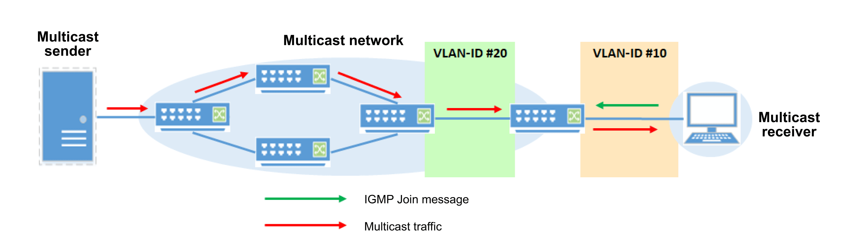
- Enable IP multicast routing.
SWX3200(config)# ip multicast-routing
- Enable IGMP and PIM for VLAN #10 and # VLAN #20.
SWX3200(config)#interface vlan10,vlan20 SWX3200(config-if)#ip pim dense-mode ... (Enable PIM-DM on VLANs #10 and #20) SWX3200(config-if)#ip igmp enable ... (Enable IGMP on VLANs #10 and #20)
- Check for multicast receiver information.
SWX3200#show ip igmp groups IGMP Connected Group Membership Group Address Interface Uptime Expires State Last Reporter 239.0.0.1 vlan10 00:01:46 00:03:07 Active 192.168.10.1 SWX3200#
- To disable multicast routing for specific VLAN interfaces, delete the IGMP and PIM settings.
- Delete the IGMP and PIM settings for VLAN #10 and # VLAN #20.
SWX3200(config)#interface vlan10,vlan20 SWX3200(config-if)#no ip pim dense-mode ... (Enable PIM-DM on VLANs #10 and #20) SWX3200(config-if)#no ip igmp enable ... (Enable IGMP on VLANs #10 and #20)
5.2 IGMP Proxy Settings
If the IGMP Proxy function is used, the upstream interface (for the multicast router) functions as an IGMP host and the downstream interface (for the multicast receiver)
functions as the IGMP querier, so that multicast traffic received from higher-level multicast routers is forwarded to multicast receivers.
In the following example, settings for the IGMP Proxy function are described.
However, it assumes VLAN and IP settings have already been specified. For more information about VLAN and IP settings, refer to PIM technical documentation.
Example of IGMP Proxy Settings
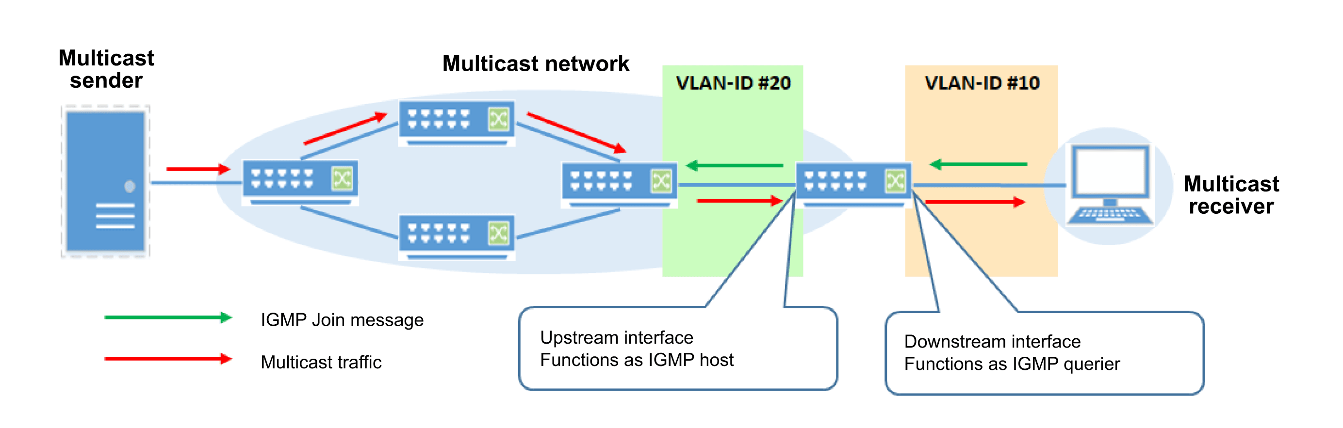
- Enable IP multicast routing.
SWX3200(config)# ip multicast-routing
- Enable IGMP for VLAN #20 and set it as the upstream interface for the IGMP Proxy function.
SWX3200(config)#interface vlan20 SWX3200(config-if)#ip igmp proxy-service ... (Specify VLAN #20 as upstream interface for IGMP Proxy function) SWX3200(config-if)#ip igmp enable ... (Enable IGMP for VLAN #20)
- Enable IGMP for VLAN #10 and set it as the downstream interface for the IGMP Proxy function. Specify VLAN #20 as the upstream interface.
SWX3200(config)#interface vlan10 SWX3200(config-if)#ip igmp mroute-proxy vlan20 ... (Specify VLAN #10 as the IGMP Proxy downstream interface and VLAN #20 as the upstream interface.) SWX3200(config-if)#ip igmp enable ... (Enable IGMP for VLAN #10)
- Check the IGMP Proxy information.
SWX3200#show ip igmp proxy groups IGMP Connected Proxy Group Membership Group Address Interface State Member state 239.0.0.1 vlan20 Active Delay
If the IGMP Proxy function is used, multiple downstream interfaces can be linked to each upstream interface.
If the IGMP Snooping function is enabled, packets from respective groups can be sent only to ports connected to a terminal that wants to receive the multicast packets.
6 Points of Caution
None
7 Related Documentation
- IP multicast functions :PIM
PIM
1 Function Overview
The following explains how to use the PIM (protocol independent multicast) multicast routing protocol.
Because multicast routing is based on unicast routing, it requires that unicast packets are appropriately routed throughout the multicast network.
PIM is a multicast routing protocol that does not depend on any particular unicast routing protocol.
That means RIP, OSPF, or any other unicast routing protocol can be used.
This product supports using the PIM Dense mode (PIM-DM), Sparse mode (PIM-SM and PIM-SSM).
PIM-DM uses the flood-and-prune model for multicasting, so that multicast traffic is temporarily flooded to all PIM neighbors.
If a PIM router has no multicast receivers for a multicast group, then a Prune message is sent to the PIM neighbors in order to stop forwarding unnecessary multicast traffic.
In contrast, PIM-DM briefly floods even networks with no multicast receivers, which is helpful for LANs with multicast receivers concentrated (dense) within a limited range of the LAN.
It also offers the advantage of simpler settings than the PIM-SM explained below.
Illustration of PIM-DM Actions
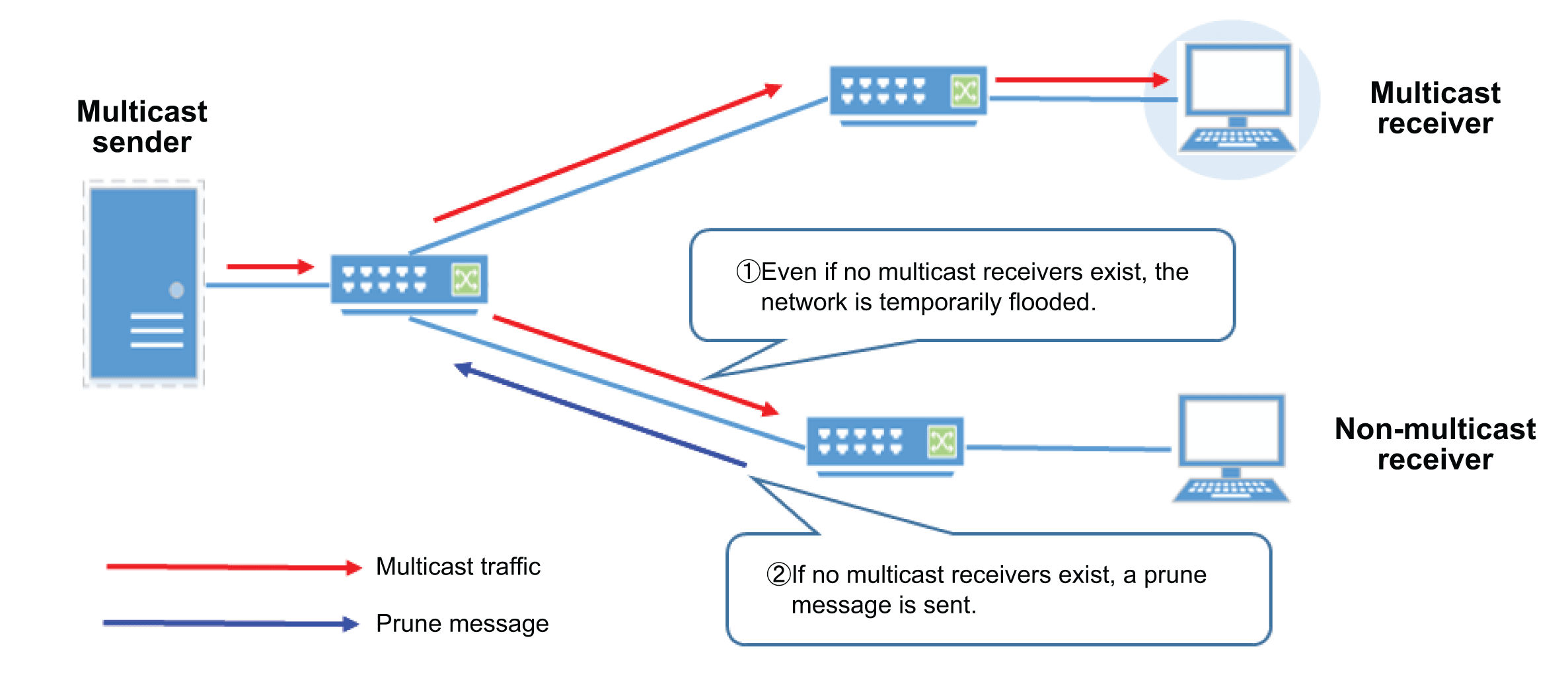
PIM-SM is based on the Explicit Join model of multicasting. Multicast traffic is forwarded only if a Join request is received for a group from a multicast receiver.
For PIM-SM, a router called a rendezvous point (RP) manages the group information and controls forwarding multicast traffic.
Specifically, PIM routers connected to a multicast receiver send multicast group Join requests to the RP. When the RP receives a Join request, it forwards multicast traffic to that PIM router.
PIM-SM minimizes network loads by forwarding multicast traffic only when necessary, which is well suited to networks with only scattered (sparse) multicast receivers.
Illustration of PIM-SM Actions
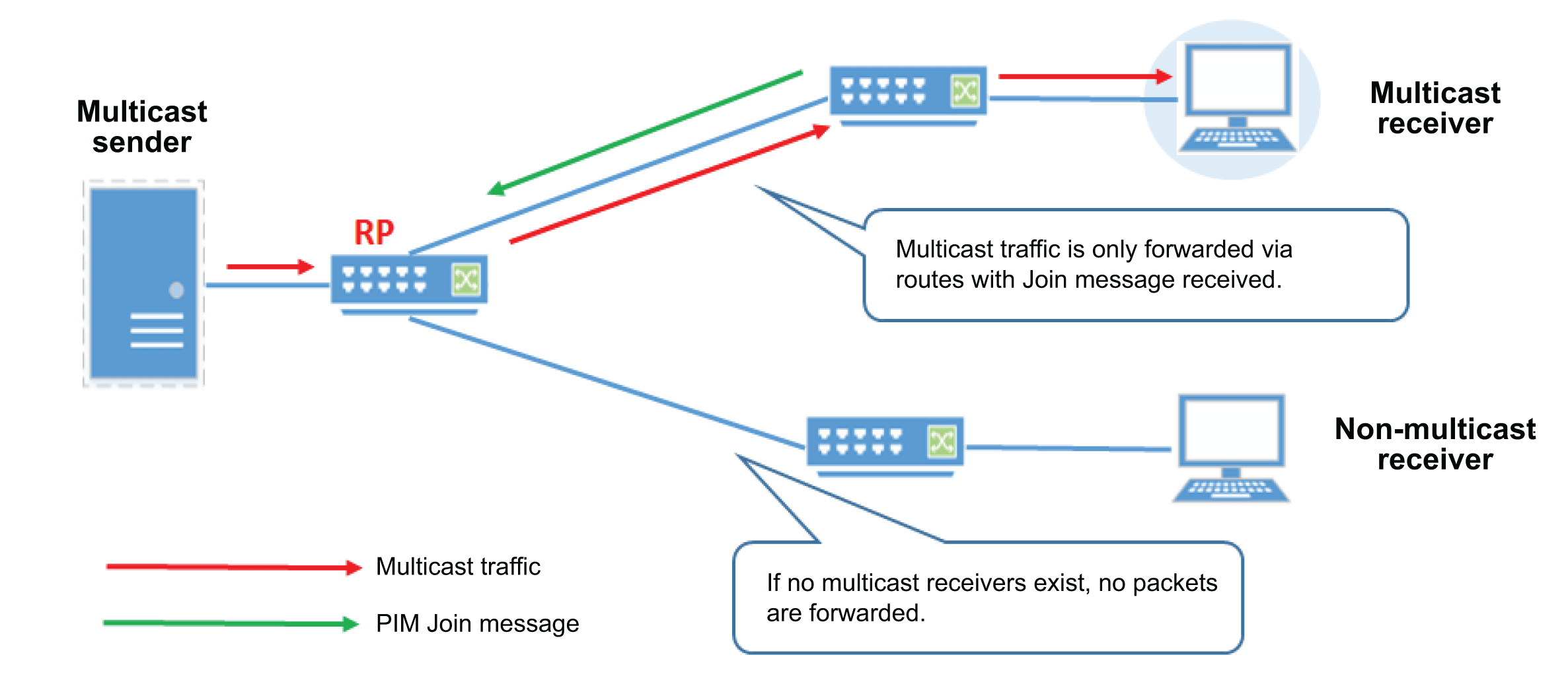
2 Definition of Terms Used
- PIM (Protocol Independent Multicast)
A type of multicasting routing protocol that does not depend on any particular unicast routing protocol.
- PIM-DM (PIM Dense Mode)
The Dense mode of the PIM multicast routing protocol. It forwards multicast packets based on the flood-and-prune model.
- PIM-SM (PIM Sparse Mode)
The Sparse mode of the PIM multicast routing protocol. It forwards multicast packets based on the Explicit Join model.
- PIM-SSM (PIM Source Specific Multicast)
This enables efficient forwarding of multicast packets by specifying multicast senders and prevents receiving invalid multicast packets.
IGMPv3 must be used to enable SSM, but by using the SSM Mapping function, SSM can be used even for hosts that only support IGMPv1 or IGMPv2.
- Equal Cost Multi Path (ECMP) Environment
Environment with multiple paths of equal cost.
- DR (Designated Router)
This router is designated for forwarding multicast packets in networks with multiple PIM-SM routers present within the same LAN.
- RP (Rendezvous Point)
This multicast traffic relaying router serves the role of connecting multicast senders and receivers within a PIM-SM network.
- BSR (Bootstrap Router)
This router is used for mapping between multicast groups and RP routers within PIM-SM networks.
- Distribution Tree
Because multicast packet forwarding involves communication from one to many, packets are forwarded from a single multicast sender to multiple multicast receivers.
Each packet is copied by the multicast router and forms tree-like distribution pathways. These distribution paths are referred to as a “distribution tree”.
- Sender Tree
This distribution tree originates with multicast senders. It is used for both PIM-DM and PIM-SM.
They are represented in the form “(S, G)”, where S represents the multicast sender IP address and G the multicast group IP address.
- Shared Tree
This distribution tree is centered around an RP. For PIM-DM, it is used in combination with sender trees.
Shared trees involve all multicast senders using one shared tree, which is represented in the (*, G).
- Reverse Path Forwarding (RPF) Check
To avoid looping or receiving the same packets multiple times during multicast forwarding, the RPF check process compares sender addresses for received multicast packets against the unicast route table and drops multicast packets received from interfaces other than via the shortest route.
- Reverse Path Forwarding (RPF) Interface
Refers to interfaces that successfully passed the RPF check and received multicast packets.
- First-Hop Router
Routers connected directly to a multicast sender.
- Last-Hop Router
Routers connected directly to a multicast receiver.
3 Function Details
PIM-DM
PIM-DM operating specifications are indicated below.
Basic PIM-DM Settings
- PIM-DM is enabled/disabled with respect to VLAN interfaces.
The initial setting is disabled for both the default VLAN (VLAN #1) and after a VLAN is generated.
PIM-DM can be enabled using the ip pim dense-mode command.
Enabling PIM-DM also automatically enables IGMP, but we recommend enabling it explicitly using the ip igmp command.
To enable PIM-DM, use the ip multicast-routing command to enable the IP Multicast Routing function (disabled in default settings) for the entire system.
Use the multicast command to enable the Multicast Routing function (enabled in default settings) for each port.
- Use the ip pim dense-mode passive command to stop sending/receiving PIM messages at applicable VLAN interfaces.
For example, that is used to suppress sending PIM messages to interfaces with no PIM neighbors and only connected to multicast receivers.
- PIM-DM uses a unicast route table for multicast packet forwarding, so use RIP, OSPF, or other means to build a unicast route table.
- In ECMP environments, enable multicast routing for all interfaces that might be bypassed by multicast traffic.
PIM Neighbor Detection Settings
- If PIM-DM is enabled, PIM neighbors are detected by sending a PIM Hello message to all PIM routers.
The following parameters can be changed for PIM Hello messages.- Use the ip pim hello-holdtime command to set how long to hold PIM Hello messages.
- Use the ip pim hello-interval command to set the interval between sending PIM Hello messages.
- By using the ip pim neighbor-filter command, the IP access list can be used to prevent forming adjacency with specific PIM routers.
Setting the PIM-DM Flooding Suppression Function
- PIM-DM floods the network every 180 seconds to maintain the distribution tree. Therefore, the default State Refresh function setting for flooding suppression is Enable.
By default, the State Refresh function sends PIM State Refresh messages from every router connected directly to a multicast sender every 60 seconds. When a PIM router receives the message, the router updates the Expire timer for the corresponding group to prevent flooding every 180 seconds.
Use the ip pim state-refresh origination-interval command to set the interval between sending PIM State Refresh messages.
- If a new multicast receiver connects to an interface with multicast packet sending stopped (Prune), then PIM-DM sends a PIM Graft message to the upstream PIM neighbor.
When the PIM neighbor receives the Graft message, it cancels the interface Prune status to allow newly added multicast receivers to immediately receive multicast packets.
By default, PIM-DM keeps resending Graft messages until successful, but the ip pim graft-retransmit command can be used to specify the maximum number of resend attempts.
PIM-SM
PIM-SM operating specifications are indicated below.
Basic PIM-SM Settings
- PIM-SM is enabled/disabled with respect to VLAN interfaces.
The initial setting is disabled for both the default VLAN (VLAN #1) and after a VLAN is generated.
PIM-SM can be enabled using the ip pim sparse-mode command.
Enabling PIM-SM also automatically enables IGMP, but we recommend enabling it explicitly using the ip igmp command.
To enable PIM-SM, use the ip multicast-routing command to enable the IP Multicast Routing function (disabled in default settings) for the entire system.
Use the multicast command to enable the Multicast Routing function (enabled in default settings) for each port.
- Use the ip pim sparse-mode passive command to stop sending/receiving PIM messages at applicable VLAN interfaces.
For example, that is used to suppress sending PIM messages to interfaces with no PIM neighbors and only connected to multicast receivers.
- PIM-SM uses a unicast route table for multicast packet forwarding, so use RIP, OSPF, or other means to build a unicast route table.
- In ECMP environments, enable multicast routing for all interfaces that might be bypassed by multicast traffic.
PIM Neighbor Detection Settings
- If PIM-SM is enabled, PIM neighbors are detected by sending a PIM Hello message to all PIM routers.
The following parameters can be changed for PIM Hello messages.- Use the ip pim hello-holdtime command to set how long to hold PIM Hello messages.
- Use the ip pim hello-interval command to set the interval between sending PIM Hello messages.
- By using the ip pim neighbor-filter command, the IP access list can be used to prevent forming adjacency with specific PIM routers.
- By default, Hello messages include an Generation ID option, which can be excluded using the ip pim exclude-genid command.
The Generation ID is an ID that is regenerated each time packets are upload to a multicast interface and used to detect route problems, due to PIM neighbors restarting, for example.
Setting the Designated Router (DR)
- If there are multiple PIM routers on the same VLAN, one of the routers can be selected as the designated router (DR).
The DR serves the role of designated forwarder of multicast packets within subnets.
During DR selection, the DR priority value of each interface is compared and the router with the highest value is designated as the DR. If DR priority values are equal, the router with the higher IP address value becomes the DR.
Use the ip pim dr-priority command to set DR priority values.
Setting Rendezvous Points (RP)
- PIM-SM requires defining rendezvous points (RP) used to forward multicast traffic, an RP specified for each multicast group.
If a group receives a Join request from a multicast receiver, then information about the router where the multicast receiver is located is registered at the RP located at the center of a shared tree.
Meanwhile, the multicast sender notifies the RP of its presence, so that multicast traffic is forwarded to the multicast receiver via the RP.
- RPs can be defined not only by using the ip pim rp address command to statically set the RP, but also by using a boot strap router (BSR) to automatically map multicast groups to RPs.
If a BSR is used, one BSR must first be selected on the PIM network. The priority value of candidate BSRs (C-BSR) are compared to select the C-BSR with the highest value as the BSR.
If they have equal BSR priority values, the router with the higher IP address is selected as the BSR. When the BSR is selected, candidate RPs (C-RP) send a C-RP notice to the BSR.
If multiple C-RPs exist, the router with the lowest RP priority value is selected as the RP and RP information is sent by a BSR message to notify all PIM routers.
However, if RP priority values are equal, the router with the highest hash value is selected as the RP. If the hash values are equal, then the router with the highest IP address value is selected as the RP.
- Use the ip pim rp-address command to statically set RPs.
- Use the ip pim rp-candidate command to operate C-RP (candidate RPs) for automatically mapping RPs by the BSR.
- If the multicast group was not specified by the ip pim rp-candidate command, then a Candidate-RP-Advertisement message is sent with default Prefix Count=0 and no group information.
To send a Candidate-RP-Advertisement message that includes Prefix Count=1 and Group=224.0.0.0/4 (all multicast groups) information, use the ip pim crp-fixed-prefix command.
- RP information can be checked using the show ip pim rp mapping command.
- RP candidate information can be checked using the show ip pim rp-hash command.
- RP information acquired from a BSR can be deleted using the clear ip pim sparse-mode bsr rp-set command.
Setting Boot Strap Routers (BSR)
- Use the ip pim bsr-candidate command to operate a BSR as a candidate BSR (C-BSR).
- By default, BSRs select RPs by comparing RP priority values and selecting the router with the lowest RP priority value as the RP.
Use the ip pim ignore-rp-set-priority command to ignore RP priority values and select RPs based on a Hash function.
- Use the ip pim bsr-border command to stop sending/receiving BSR messages at the PIM network multicast border.
- BSR information can be checked using the show ip pim bsr-router command.
Setting Register Messages
- First-hop routers connected to multicast senders send a Register message to RPs to notify them that a multicast sender is present.
When a Register message is sent, the IP address of the RPF interface connected to the multicast sender is used as the sender address, but the sender address can also be specified explicitly using the ip pim register command.
- Use the ip pim accept-register command to filter Register messages at RPs.
Filtering using the IP access list to filter based on IPv4 address of multicast senders.
- Use the ip pim register-rate-limit command to set the Register message sending rate (maximum number of packets per second).
- The default checksum calculation method for Register messages is only based on the header. Checksum values can also be calculated based on all packets using the ip pim register-checksum all command.
- When a first-hop router receives a Register-Stop message, it stops sending Register messages for a specified time.
After receiving a Register-Stop message, the default time to wait before sending Register messages again (Register suppression timeout) is 60 seconds, but the time setting can be changed using the ip pim register-suppression command.
Settings Related to Configuring Multicast Routes
- PIM routers periodically send Join or Prune messages to configure multicast routing.
The default interval between sending PIM Join or Prune messages is 60 seconds.
The interval between sending PIM Join or Prune messages can be changed using the ip pim jp-timer command.
- Multicast route information includes a keep-alive timer (KAT) for (S, G) entries that deletes the (S, G) entries when the KAT number of seconds have elapsed after there is no data traffic from multicast senders at RPs.
KAT values can be set using the ip pim rp-register-kat command. If no ip pim rp-register-kat command setting exists, it is automatically calculated to decide the KAT value.
- When a multicast receiver is serving as a last-hop router under an interface, PIM-SM is able to switch the multicast sending route to the shortest-path tree (SPT) via an RP shared tree.
By default, switching to the SPT is enabled.
To disable switching to the SPT so that multicast packets are always forwarded via an RP, use the ip pim spt-disable command.
PIM-SSM Settings
- PIM-SSM (PIM source specific multicast) is an extension of PIM-SM that sends multicast traffic via the shortest-path tree , rather than via RPs, based on the multicast receiver specifying a specific multicast sender.
PIM-SSM is enabled using the ip pim ssm command.
- PIM-SSM uses the 232.0.0.0/8 (232.0.0.0 to 232.255.255.255) range of multicast group addresses for standard SSM, but addresses can be specified using the ip pim ssm command.
- Using multicast groups within the SSM range requires that multicast receivers support IGMPv3.
However, by enabling the SSM Mapping function in IGMP, multicast receivers with IGMPv1 or IGMPv2 can also joint groups in the SSM range.
Compatibility Settings for Older Standards
- The ip pim register-rp-reachability command can be used to enable checking RP-reachability messages used by older PIMv1 standards.
With default settings, RP-reachability messages are not checked.
- Use the ip pim unicast-bsm command to enable sending/receiving unicast BSMs.
4 Related Commands
Related commands are indicated below.
For details on the commands, refer to the Command Reference.
List of PIM-Related Shared Commands
| Operations | Operating Commands |
|---|---|
| Hello message sending interval setting | ip pim hello-interval |
| Hello message hold time setting | ip pim hello-holdtime |
| Setting for preventing PIM neighbor relationships | ip pim neighbor-filter |
| Shows PIM interface information | show ip pim interface |
| Shows PIM multicast route table | show ip pim mroute |
| Shows PIM neighbor information | show ip pim neighbor |
| Shows next-hop information used by PIM | show ip pim nexthop |
List of PIM-DM-Related Commands
| Operations | Operating Commands |
|---|---|
| Enables/disables PIM-DM | ip pim dense-mode |
| State refresh message sending interval setting | ip pim state-refresh origination interval |
| Maximum number of times to resend PIM graft messages | ip pim graft-retransmit |
| Estimated delay time setting for sending PIM messages | ip pim propagation-delay |
List of PIM-SM-Related Commands
| Operations | Operating Commands |
|---|---|
| Enables/disables PIM-SM | ip pim sparse-mode |
| Setting for not including GenID information in hello messages | ip pim exclude-genid |
| Designated router priority value setting | ip pim dr-priority |
| Static RP settings | ip pim rp-address |
| Enables/disables function as a C-RP | ip pim rp-candidate |
| C-RP advertisement message sending method setting | ip pim crp-fixed-prefix |
| Enables/disables function as C-BSR | ip pim bsr-candidate |
| Setting to stop sending/receiving BSR messages | ip pim bsr-border |
| Setting for ignoring RP priority and selecting RP based only on hush function | ip pim ignore-rp-set-priority |
| Register message sender IP address setting | ip pim register-source |
| Enables/disables filtering register messages at RPs | ip pim accept-register |
| Sets number of packets sendable per second in register messages | ip pim register-rate-limit |
| Sets checksum calculation method for register messages | ip pim register-checksum |
| Sets register suppression timeout value | ip pim register-suppression |
| Sets interval between sending join or prune messages | ip pim jp-timer |
| Sets keep-alive timer value for (S,G) entries | ip pim rp-register-kat |
| Disables switching to SPT | ip pim spt-disable |
| Enables/disables PIM-SSM | ip pim ssm |
| Enables/disables sending/receiving unicast BSMs | ip pim unicast-bsm |
| Enables/disables checking RP-reachability messages | ip pim register-rp-reachability |
| Shows RP information | show ip pim rp mapping |
| Shows RP candidate information | show ip pim rp-hash |
| Shows boot strap router information | show ip pim bsr-router |
| Clears RP information acquired from BSRs | clear ip pim sparse-mode bsr rp-set |
5 Examples of Command Execution
5.1 PIM-DM Settings
If PIM-DM is used, then PIM-related settings are identical for all PIM routers.
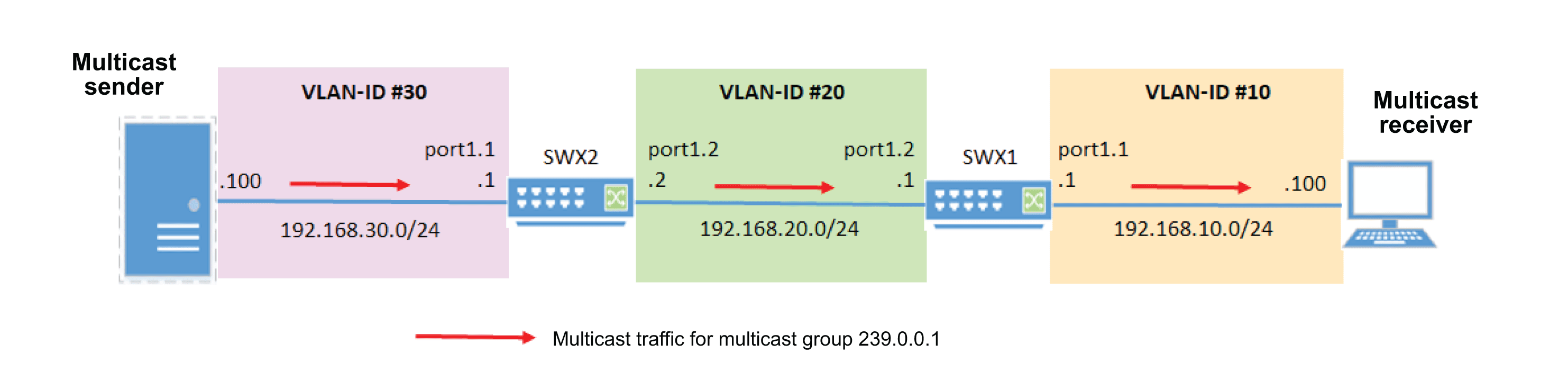
■ Specifying SWX1 Settings
- Create VLAN #10 and VLAN #20.
SWX1(config)#vlan database SWX1(config-vlan)#vlan 10 ... (Create VLAN #10) SWX1(config-vlan)#vlan 20 ... (Create VLAN #20) SWX1(config-vlan)#exit
- Associate port1.1 to VLAN !#10 and port1.2 to VLAN !#20 as access ports.
SWX1(config)#interface port1.1 SWX1(config-if)#switchport access vlan 10 ... (Associate port1.1 to VLAN #10) SWX1(config-if)#exit SWX1(confige)#interface port1.2 SWX1(config-if)#switchport access vlan 20 ... (Associate port1.2 to VLAN #20) SWX1(config-if)#exit
- Specify IP addresses for VLAN #10 and VLAN #20.
SWX1(config)#interface vlan10 SWX1(config-if)#ip address 192.168.10.1/24 ... (Specify an IP address for VLAN #10) SWX1(config-if)#exit SWX1(config)#interface vlan20 SWX1(config-if)#ip address 192.168.20.1/24 ... (Specify an IP address for VLAN #20) SWX1(config-if)#exit
- Enable IP multicast routing.
SWX(config)# ip multicast-routing
- Enable IGMP and PIM-DM for VLAN #10 and VLAN #20.
SWX1(config)#interface vlan10,vlan20 SWX1(config-if)#ip pim dense-mode ... (Enable PIM-DM on VLANs #10 and #20) SWX1(config-if)#ip igmp enable ... (Enable IGMP on VLANs #10 and #20) SWX1(config-if)#exit
- Set the unicast route.
SWX1(config)# ip route 192.168.30.0/24 192.168.20.2
■ Specifying SWX2 Settings
- Create VLAN #20 and VLAN #30.
SWX2(config)#vlan database SWX2(config-vlan)#vlan 20 ... (Create VLAN #20) SWX2(config-vlan)#vlan 30 ... (Create VLAN #30) SWX2(config-vlan)#exit
- Associate port1.1 to VLAN !#30 and port1.2 to VLAN !#20 as access ports.
SWX2(config)#interface port1.1 SWX2(config-if)#switchport access vlan 30 ... (Associate port1.1 to VLAN #30) SWX2(config-if)#exit SWX2(confige)#interface port1.2 SWX2(config-if)#switchport access vlan 20 ... (Associate port1.2 to VLAN #20) SWX2(config-if)#exit
- Specify IP addresses for VLAN #20 and VLAN #30.
SWX2(config)#interface vlan20 SWX2(config-if)#ip address 192.168.20.2/24 ... (Specify an IP address for VLAN #20) SWX2(config-if)#exit SWX2(config)#interface vlan30 SWX2(config-if)#ip address 192.168.30.1/24 ... (Specify an IP address for VLAN #30) SWX2(config-if)#exit
- Enable IP multicast routing.
SWX2(config)# ip multicast-routing
- Enable IGMP and PIM-DM for VLAN #20 and VLAN #30.
SWX2(config)#interface vlan20,vlan30 SWX2(config-if)#ip pim dense-mode ... (Enable PIM-DM on VLANs #20 and #30) SWX2(config-if)#ip igmp enable ... (Enable IGMP on VLANs #20 and #30) SWX2(config-if)#exit
- Set the unicast route.
SWX2(config)# ip route 192.168.10.0/24 192.168.20.1
■ Confirmation
- After the multicast sender sends multicast traffic, check the multicast route at SWX1.
SWX1#show ip mroute IP Multicast Routing Table Flags: I - Immediate Stat, T - Timed Stat, F - Forwarder installed Timers: Uptime/Stat Expiry Interface State: Interface (TTL) (192.168.30.100, 239.0.0.1), uptime 00:00:10 Owner PIM-DM, Flags: F Incoming interface: vlan20 Outgoing interface list: vlan10 (1)
5.2 PIM-SM Settings
PIM-SM requires specifying RPs.
For automatic RP selection, both RPs and BSRs must be specified. If RPs are specified statically, then BSR settings are not necessary.
PIM-SM Setting Example (Using BSRs)
The following example describes specifying PIM-SM settings based on using BSRs to select RPs automatically.
Set candidate RP (C-RP) and candidate BSR (C-BSR) settings for SWX1. Then set SWX2 as the RP and BSR.
Redundancy is recommended, by setting C-RP and C-BSR setting in multiple PIM routers.
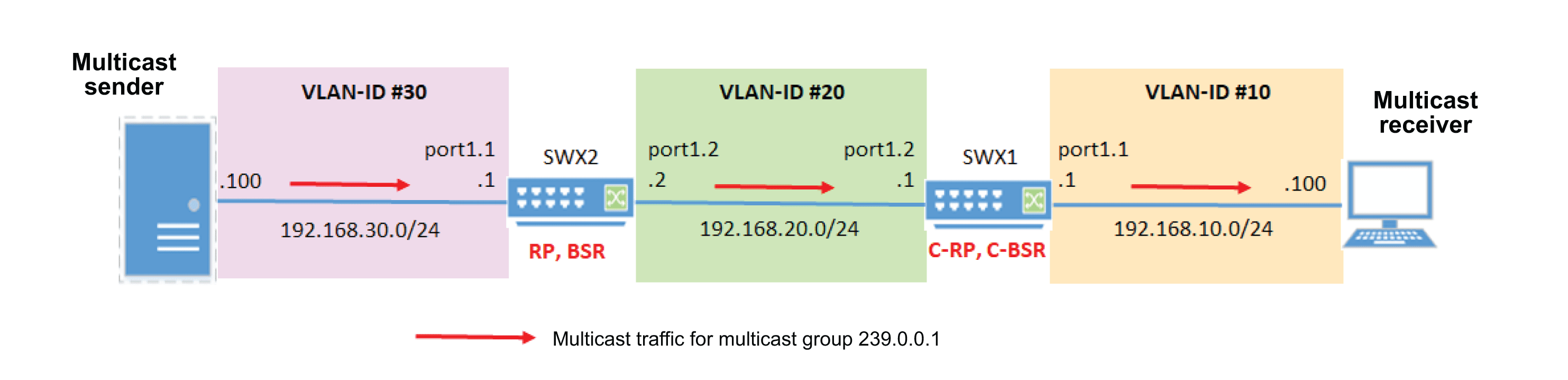
■ Specifying SWX1 (C-RP and C-BSR) Settings
- Create VLAN #10 and VLAN #20.
SWX1(config)#vlan database SWX1(config-vlan)#vlan 10 ... (Create VLAN #10) SWX1(config-vlan)#vlan 20 ... (Create VLAN #20) SWX1(config-vlan)#exit
- Associate port1.1 to VLAN !#10 and port1.2 to VLAN !#20 as access ports.
SWX1(config)#interface port1.1 SWX1(config-if)#switchport access vlan 10 ... (Associate port1.1 to VLAN #10) SWX1(config-if)#exit SWX1(confige)#interface port1.2 SWX1(config-if)#switchport access vlan 20 ... (Associate port1.2 to VLAN #20) SWX1(config-if)#exit
- Specify IP addresses for VLAN #10 and VLAN #20.
SWX1(config)#interface vlan10 SWX1(config-if)#ip address 192.168.10.1/24 ... (Specify an IP address for VLAN #10) SWX1(config-if)#exit SWX1(config)#interface vlan20 SWX1(config-if)#ip address 192.168.20.1/24 ... (Specify an IP address for VLAN #20) SWX1(config-if)#exit
- Enable IP multicast routing.
SWX(config)# ip multicast-routing
- Enable IGMP and PIM-SM for VLAN #10 and VLAN #20.
SWX1(config)#interface vlan10,vlan20 SWX1(config-if)#ip pim sparse-mode ... (Enable PIM-SM on VLANs #10 and #20) SWX1(config-if)#ip igmp enable ... (Enable IGMP on VLANs #10 and #20) SWX1(config-if)#exit
- Operate it as a C-RP to advertise the IP address specified for VLAN #10 (192.168.10.1). Leave the default RP priority values unchanged.
SWX(config)# ip pim rp-candidate vlan10
- Operate it as a C-BSR to advertise the IP address specified for VLAN #10 (192.168.10.1). Leave the default BSR priority values unchanged.
SWX(config)# ip pim bsr-candidate vlan10
- Set the unicast route.
SWX1(config)# ip route 192.168.30.0/24 192.168.20.2
■ Specifying SWX2 (RP and BSR) Settings
- Create VLAN #20 and VLAN #30.
SWX2(config)#vlan database SWX2(config-vlan)#vlan 20 ... (Create VLAN #20) SWX2(config-vlan)#vlan 30 ... (Create VLAN #30) SWX2(config-vlan)#exit
- Associate port1.1 to VLAN !#30 and port1.2 to VLAN !#20 as access ports.
SWX2(config)#interface port1.1 SWX2(config-if)#switchport access vlan 30 ... (Associate port1.1 to VLAN #30) SWX2(config-if)#exit SWX2(confige)#interface port1.2 SWX2(config-if)#switchport access vlan 20 ... (Associate port1.2 to VLAN #20) SWX2(config-if)#exit
- Specify IP addresses for VLAN #20 and VLAN #30.
SWX2(config)#interface vlan20 SWX2(config-if)#ip address 192.168.20.2/24 ... (Specify an IP address for VLAN #20) SWX2(config-if)#exit SWX2(config)#interface vlan30 SWX2(config-if)#ip address 192.168.30.1/24 ... (Specify an IP address for VLAN #30) SWX2(config-if)#exit
- Enable IP multicast routing.
SWX2(config)# ip multicast-routing
- Enable IGMP and PIM-SM for VLAN #20 and VLAN #30.
SWX2(config)#interface vlan20,vlan30 SWX2(config-if)#ip pim sparse-mode ... (Enable PIM-SM on VLANs #20 and #30) SWX2(config-if)#ip igmp enable ... (Enable IGMP on VLANs #20 and #30) SWX2(config-if)#exit
- Operate it as a C-RP to advertise the IP address specified for VLAN #30 (192.168.30.1). Set the default RP priority value to a value less than 192, so that it is prioritized for RP selection.
SWX(config)# ip pim rp-candidate vlan30 priority 190
- Operate it as a C-BSR to advertise the IP address specified for VLAN #30 (192.168.30.1). Set the default BSR priority value to a value larger than 64, so that it is prioritized for BSR selection.
SWX(config)# ip pim bsr-candidate vlan30 0 70
- Set the unicast route.
SWX2(config)# ip route 192.168.10.0/24 192.168.20.1
■ Confirmation
- After the multicast sender sends multicast traffic, check the multicast route at SWX1.
SWX1#show ip mroute IP Multicast Routing Table Flags: I - Immediate Stat, T - Timed Stat, F - Forwarder installed Timers: Uptime/Stat Expiry Interface State: Interface (TTL) (192.168.30.100, 239.0.0.1), uptime 00:02:46, stat expires 00:03:14 Owner PIM-SM, Flags: TF Incoming interface: vlan20 Outgoing interface list: vlan10 (1) - Confirm that SWX2 (192.168.30.1) was selected as the RP.
SWX1#show ip pim rp-hash 239.0.0.1 RP: 192.168.30.1 Info source: 192.168.30.1, via bootstrap
PIM-SM Setting Example (with RPs specified statically)
The following example describes specifying PIM-SM settings based on specifying RPs statically.
To specify RPs statically, identical RP IP addresses must be specified in all PIM routers.
Execute the following commands at all PIM routers, instead of the ip pim rp-candidate and ip pim bsr-candidate commands described in the PIM-SM setting example using BSRs.
- Set RP IP addresses to 192.168.30.1.
SWX(config)# ip pim rp-address 192.168.30.1
PIM-SSM Setting Example
The following example describes specifying PIM-SSM settings.
PIM-SSM requires enabling PIM-SM, but the settings are identical for all PIM routers because RPs and BSRs do not need to be specified when using the method of restricting multicast senders.
Note that RP settings are required if also using PIM-SSM for multicast groups outside the SSM range.
Configuring settings for the following commands instead of the ip pim rp-candidate and ip pim bsr-candidate commands described in the PIM-SM setting example using BSRs.
However, note that if PIM-SSM is used, IPv4 addresses of multicast senders must be specified in IGMPv3 Report information used by multicast receivers to send group Join requests.
- Enable PIM-SSM. Use 239.0.0.1 as the SSM range. (If the ip pim ssm command was used to specify the default keyword, then use the standard SSM range of 232.0.0.0/8.)
SWX(config)# access-list 1 permit any 239.0.0.1 0.0.0.0 any SWX(config)# ip pim ssm range 1
However, use the IGMP SSM Mapping function for multicast receivers running IGMPv1 or IGMPv2 to use SSM.
Using IGMP Querier to associate multicast groups with multicast senders in advance will enable sending (S, G) Join requests to corresponding groups.
In the following example, IGMPv1/IGMPv2 Join requests (*, 239.0.0.1) will be interpreted as a request to join (192.168.30.1, 239.0.0.1) by IGMPv3.
- Enable the IGMP SSM Mapping function.
SWX(config)# ip igmp ssm-map enable
- Associate the multicast group 239.0.0.1 to the multicast sender 192.168.30.1.
SWX(config)# access-list 1 permit any 239.0.0.1 0.0.0.0 any SWX(config)# ip igmp ssm-map static 1 192.168.30.1
6 Points of Caution
None
7 Related Documentation
- IP multicast functions :IGMP
- SWX3220 Series Technical Data (Basic Functions)
- Traffic control functions
ACL
1 Function Overview
The access list (ACL) is a conditional statement that determines whether to permit or to deny the frame.
If the access list is applied to the interface, only the permitted frame will be transferred, and the denied frame will be discarded.
As this allows for only specified frames to be selected for transfer, this feature is primarily used for security purposes.
This product supports three access list types, as shown in the table below.
Access list type
| Access list type | Deciding criteria | Access list ID | Purpose of use |
|---|---|---|---|
| IPv4 access list | Source IPv4 address Destination IPv4 address IP protocol type | 1–2000 | Filters access from specific hosts and networks. Filters specific IP protocol types such as TCP/UDP. |
| IPv6 access list | Source IPv6 address | 3001–4000 | Filters access from specific hosts and networks. |
| MAC access list | Source MAC address Destination MAC address | 2001–3000 | Filters access and data transfer from specific devices. |
2 Definition of Terms Used
- ACL
- Abbreviation of “Access Control List”.
- Wildcard mask
Information that specifies which portion of the specified IPv4 address or MAC address is read. This is used when specifying a range of IPv4 addresses or MAC addresses as ACL conditions.
- When the wildcard mask bit is “0”: check the corresponding bit
- When the wildcard mask bit is “1”: do not check the corresponding bit
Examples of settings using wildcard masks are shown below. (The underlined portion is the wildcard mask.)
- To specify conditions for subnet 192.168.1.0/24: 192.168.1.0 0.0.0.255 (specified as decimal)
- To specify conditions for vendor code 00-A0-DE-*-*-*: 00A0.DE00.0000 0000.00FF.FFFF (specified as hexadecimal)
3 Function Details
3.1 Generating an access list
Access lists for the number of IDs in each access list number can be generated. (Refer to the table in "1 Function Overview”.)
A maximum of 768 control parameters can be registered per list for access lists.
If the registered control conditions are not satisfied, forwarding occurs as usual.
3.2 Applying to the interface
The following table shows how access lists are applied to the input/output interfaces of this product.
Note that one access list can be applied to the IN and OUT respectively for an interface.
- Status of access list application to the interface
Access list type LAN/SFP port VLAN interface Static/LACP logical interface in out in out in out IPv4 access list ✓ ✓(*) ✓ ✓(*) ✓ - IPv6 access list ✓ ✓ ✓ ✓ ✓ - MAC access list ✓ - ✓ - ✓ - (*) As a limitation, an IPv4 access list that specifies a range of port numbers cannot be applied to the output (out) side of an interface.
The number of access lists that can be applied to the interface depends on the number of control parameters that are registered in the access lists.
On this product, a maximum of 1536 control parameters can be registered to the interface.
Applying an access list to the interface will use resources “equivalent to the number of control parameters that are registered in the access list”.
However, control parameters may also be used internally within the system in some cases, and use resources accordingly.
3.3 Settings for the LAN/SFP port and logical interface
The steps for applying an access list to a LAN/SFP port and to a logical interface is shown below.
- Decide on the filtering parameters, and generate the access list.
- Add explanatory text as necessary.
- Check the access list.
- Apply the access list to the LAN/SFP port and logical interface.
- Check the applied access list.
A list of operation commands is given below.
Access list operation commands (when applied to the LAN/SFP port and logical interface)
| Access list type | Generate access list | Check access list | Apply access list | Check the applied access list |
|---|---|---|---|---|
| IPv4 access list | access-list | show access-list | access-group | show access-group |
| IPv6 access list | access-list | show access-list | access-group | show access-group |
| MAC access list | access-list | show access-list | access-group | show access-group |
3.4 VLAN interface settings
The steps for applying access lists to the VLAN interface are shown below.
- Decide on the filtering parameters, and generate the access list.
- Add explanatory text as necessary.
- Check the access list.
- Generate the VLAN access map.
- Set the access list for the VLAN access map.
- Check the VLAN access map.
- Apply the VLAN access map to the VLAN.
- Check the VLAN access map that was applied.
The operations in steps 1 and 2 are the same as those shown in 3.3.
The following is a list of operating commands for steps 3. and following.
VLAN access map operating command
| Access list type | VLAN access map generation | Settings for access list used with VLAN access map | VLAN access map confirmation | VLAN access map application | Confirmation of the applied VLAN access map |
|---|---|---|---|---|---|
| IPv4 access list | vlan access-map | match access-list | show vlan access-map | vlan filter | show vlan filter |
| IPv6 access list | vlan access-map | match access-list | show vlan access-map | vlan filter | show vlan filter |
| MAC access list | vlan access-map | match access-list | show vlan access-map | vlan filter | show vlan filter |
4 Related Commands
The related commands are shown below.
For details on the commands, refer to the Command Reference.
List of related commands
| Operations | Operating Commands |
|---|---|
| Apply IPv4 access list | access-group |
| Generate IPv4 access list | access-list |
| Add IPv4 access list explanatory text | access-list description |
| Apply IPv4 access list | access-group |
| Generate IPv6 access list | access-list |
| Add IPv6 access list explanatory text | access-list description |
| Apply IPv6 access list | access-group |
| Generate MAC access list | access-list |
| Add MAC access list explanatory text | access-list description |
| Apply MAC access list | access-group |
| Show generated access list | show access-list |
| Show access list applied to interface | show access-group |
| Create VLAN access map | vlan access-map |
| Set VLAN access map parameters | match |
| Assign VLAN access map to VLAN | vlan filter |
| Show VLAN access map | show vlan access-map |
| Show VLAN access map filter | show vlan filter |
5 Examples of Command Execution
5.1 IPv4 access list settings
5.1.1 Example of application to a LAN port
■ Specify host
In this example, we will set LAN port #1 only to permit access from host:192.168.1.1 to host:10.1.1.1.
With #123 as the access list ID, add IPV4-ACL-EX as access list explanatory text using.
- Generate and confirm access list #123.
Yamaha(config)#access-list 123 permit any host 192.168.1.1 host 10.1.1.1 ... (Generate access list) Yamaha(config)#access-list 123 deny any any any Yamaha(config)#access-list 123 description IPV4-ACL-EX ... (Add access list explanatory text) Yamaha(config)#end Yamaha# Yamaha#show access-list 123 ... (Check access list) IPv4 access list 123 10 permit any host 192.168.1.1 host 10.1.1.1 20 deny any any any Yamaha# - Apply access list #123 to LAN port #1.
Yamaha(config)#interface port1.1 Yamaha(config-if)#access-group 123 in ... (Apply access list) Yamaha(config-if)#end Yamaha# Yamaha#show access-group ... (Check access list setting) Interface port1.1 : IPv4 access group 123 in
To change the access list (delete or add a setting), application of the list to the LAN port must be temporarily canceled.
For the setting indicated above, delete the setting that allows access from host: 192.168.1.1 to host: 10.1.1.1 and add a setting that allows access from host: 192.168.1.1 to host: 10.1.1.2.
- Temporarily cancel the application of access list #123 from LAN port #1.
Yamaha(config)#interface port1.1 Yamaha(config-if)#no access-group 123 in ... (Cancel application of access list)
- Delete, add, and then check the setting in access list #123.
Yamaha(config)#no access-list 123 10 ... (Delete from access list) Yamaha(config)#access-list 123 10 permit any host 192.168.1.1 host 10.1.1.2 ... (Add to access list) Yamaha(config)#end Yamaha# Yamaha#show access-list 123 ... (Check access list) IPv4 access list 123 10 permit any host 192.168.1.1 host 10.1.1.2 20 deny any any any - Apply access list #123 to LAN port #1 again.
Yamaha(config)#interface port1.1 Yamaha(config-if)#access-group 123 in ... (Apply access list)
■ Specify network
In this example, we will set LAN port #1 to permit access from network: 192.168.1.0/24 to host: 10.1.1.1.
With #123 as the access list ID, add IPV4-ACL-EX as access list explanatory text using.
- Generate and confirm access list #123.
Yamaha(config)#access-list 123 permit any 192.168.1.0 0.0.0.255 host 10.1.1.1 ... (Generate access list) Yamaha(config)#access-list 123 deny any any any Yamaha(config)#access-list 123 description IPV4-ACL-EX ... (Add access list explanatory text) Yamaha(config)#end Yamaha# Yamaha#show ip access-list ... (Check ACL) IPv4 access list 123 10 permit any 192.168.1.0/24 host 10.1.1.1 20 deny any any any Yamaha# - Apply access list #123 to LAN port #1.
Yamaha(config)#interface port1.1 Yamaha(config-if)#access-group 123 in ... (Apply access list) Yamaha(config-if)#end Yamaha# Yamaha#show access-group ... (Check access list setting) Interface port1.1 : IPv4 access group 123 in
To change the access list (delete or add a setting), application of the list to the LAN port must be temporarily canceled.
The specific procedure is the same as for specifying a host.
5.1.2 Example of application to the VLAN interface
■ Specify host
In this example, we will set VLAN #1000 only to permit access from host:192.168.1.1 to host:10.1.1.1.
We will use access list ID #123.
The VLAN access map to be used will be VAM-002, and access list #123 will be set.
- Generate and confirm access list #123.
Yamaha(config)#access-list 123 permit any host 192.168.1.1 host 10.1.1.1 ... (Generate access list) Yamaha(config)#access-list 123 deny any any any Yamaha(config)#end Yamaha# Yamaha#show access-list 123 ... (Check access list) IPv4 access list 123 10 permit any host 192.168.1.1 host 10.1.1.1 20 deny any any any - Generate VLAN access map VAM-002, and set access list #123.
Yamaha(config)#vlan access-map VAM-002 ... (Generate VLAN access map) Yamaha(config-vlan-access-map)#match access-list 123 ... (Register access list) Yamaha(config-vlan-access-map)#end Yamaha# Yamaha#show vlan access-map ... (Check VLAN access map and access list settings) Vlan access-map VAM-002 match ipv4 access-list 123 - Apply VLAN access map VAM-002 to VLAN #1000, and confirm the status.
Yamaha(config)#vlan filter VAM-002 1000 in ... (Apply VLAN access map to VLAN) Yamaha(config)#end Yamaha# Yamaha#show vlan filter ... (Check VLAN access map settings) Vlan filter VAM-002 is applied to vlan 1000 in
To change the access list (delete or add a setting), it is necessary to temporarily cancel applying the list to the VLAN interface and the setting in the VLAN access map.
For the setting indicated above, delete the setting that allows access from host: 192.168.1.1 to host: 10.1.1.1 and add a setting that allows access from host: 192.168.1.1 to host: 10.1.1.2.
- Temporarily cancel VLAN access map VAM-002 from being applied to VLAN #1000.
Yamaha(config)#no vlan filter VAM-002 1000 in ... (Delete application of VLAN access map from VLAN)
- Temporarily cancel the access list #123 setting in VLAN access map VAM-002.
Yamaha(config)#vlan access-map VAM-002 ... (Change VLAN access map) Yamaha(config-vlan-access-map)#no match access-list 123 ... (Unregister access list)
- Delete, add, and then check the setting in access list #123.
Yamaha(config)#no access-list 123 10 ... (Delete from access list) Yamaha(config)#access-list 123 10 permit any host 192.168.1.1 host 10.1.1.2 ... (Add to access list) Yamaha(config)#end Yamaha# Yamaha#show access-list 123 ... (Check access list) IPv4 access list 123 10 permit any host 192.168.1.1 host 10.1.1.2 20 deny any any any - Specify the access list #123 setting in VLAN access map VAM-002 again.
Yamaha(config)#vlan access-map VAM-002 ... (Change VLAN access map) Yamaha(config-vlan-access-map)#match access-list 123 ... (Register access list)
- Apply VLAN access map VAM-002 to VLAN #1000 again.
Yamaha(config)#vlan filter VAM-002 1000 in ... (Apply VLAN access map to VLAN)
■ Specify network
In this example, we will set VLAN port #1000 only to permit access from network:192.168.1.0/24 to host:10.1.1.1.
We will use access list ID #123.
The VLAN access map to be used will be VAM-002, and access list #123 will be set.
- Generate and confirm access list #123.
Yamaha(config)#access-list 123 permit any 192.168.1.0 0.0.0.255 host 10.1.1.1 ... (Generate access list) Yamaha(config)#access-list 123 deny any any any Yamaha(config)#end Yamaha# Yamaha#show access-list 123 ... (Check access list) IPv4 access list 123 10 permit any 192.168.1.0/24 host 10.1.1.1 20 deny any any any - Generate VLAN access map VAM-002, and set access list #123.
Yamaha(config)#vlan access-map VAM-002 ... (Generate VLAN access map) Yamaha(config-vlan-access-map)#match access-list 123 ... (Register access list) Yamaha(config-vlan-access-map)#end Yamaha# Yamaha#show vlan access-map ... (Check VLAN access map and access list settings) Vlan access-map VAM-002 match ipv4 access-list 123 - Apply VLAN access map VAM-002 to VLAN #1000, and confirm the status.
Yamaha(config)#vlan filter VAM-002 1000 in ... (Apply VLAN access map to VLAN) Yamaha(config)#end Yamaha# Yamaha#show vlan filter ... (Check VLAN access map settings) Vlan filter VAM-002 is applied to vlan 1000 in
To change the access list (delete or add a setting), it is necessary to temporarily cancel applying the list to the VLAN interface and the setting in the VLAN access map.
The specific procedure is the same as for specifying a host.
5.1.3 Allowing only TCP communication from one direction (example using TCP flags)
Given VLAN10 and VLAN20, this example controls TCP communication so that it occurs in one direction.
- Communication from VLAN10 to VLAN20 is possible by Telnet, etc.
- Communication from VLAN20 to VLAN10 is not possible by Telnet, etc.
- Generate access list #1.
Specify settings that only allow IPv4 TCP packets with an ACK or RST flag.Yamaha(config)#access-list 1 permit tcp any any ack ... (Set access list) Yamaha(config)#access-list 1 permit tcp any any rst Yamaha(config)#access-list 1 deny any any any Yamaha(config)#end Yamaha# Yamaha#show access-list ... (Check access list setting) IPv4 access list 1 10 permit tcp any any ack 20 permit tcp any any rst 30 deny any any any - Generate VLAN access map VAM-ESTABLISHED and specify access list #1.
Yamaha(config)#vlan access-map VAM-ESTABLISHED ... (Generate VLAN access map) Yamaha(config-vlan-access-map)#match access-list 1 ... (Register access list) Yamaha(config-vlan-access-map)#end Yamaha# Yamaha#show vlan access-map ... (Confirm VLAN access map setting) Vlan access-map VAM-ESTABLISHED match ipv4 access-list 1 - Apply VLAN access map VAM-ESTABLISHED to VLAN #20.
Yamaha(config)#vlan filter VAM-ESTABLISHED 20 in ... (Apply VLAN access map to VLAN) Yamaha(config)#end Yamaha# Yamaha#show vlan filter ... (Confirm application status to VLAN) Vlan filter VAM-ESTABLISHED is applied to vlan 20 in
5.2 IPv6 access list settings
5.2.1 Example of application to a LAN port
■ Specify host
In this example, specify settings that only permit LAN port #1 access from host: 2001:db8::1.
With #3001 as the access list ID, add IPV6-ACL-EX as access list explanatory text using.
- Generate and confirm access list #3001.
Yamaha(config)#access-list 3001 permit 2001:db8::1/128 ... (Generate access list) Yamaha(config)#access-list 3001 deny any Yamaha(config)#access-list 3001 description IPV6-ACL-EX ... (Add access list explanatory text) Yamaha(config)#end Yamaha# Yamaha#show access-list 3001 ... (Check access list) IPv6 access list 3001 10 permit 2001:db8::1/128 20 deny any - Apply access list #3001 to LAN port #1.
Yamaha(config)#interface port1.1 Yamaha(config-if)#access-group 3000 in ... (Apply access list) Yamaha(config-if)#end Yamaha# Yamaha#show access-group ... (Check access list setting) Interface port1.1 : IPv6 access group 3001 in
To change the access list (delete or add a setting), application of the list to the LAN port must be temporarily canceled. For the specific procedure, refer to 5.1.1 Example of application to a LAN port in 5.1 IPv4 access list settings.
■ Specify network
In this example, specify settings that only permit LAN port #1 access from network: 2001:db8::/64.
With #3001 as the access list ID, add IPV6-ACL-EX as access list explanatory text using.
- Generate and confirm access list #3001.
Yamaha(config)#access-list 3001 permit 2001:db8::/64 ... (Generate access list) Yamaha(config)#access-list 3001 deny any Yamaha(config)#access-list 3001 description IPV6-ACL-EX ... (Add access list explanatory text) Yamaha(config)#end Yamaha# show access-list 3001 ... (Check access list) IPv6 access list 3001 10 permit 2001:db8::/64 20 deny any - Apply access list #3001 to LAN port #1.
Yamaha(config)#interface port1.1 Yamaha(config-if)#access-group 3001 in ... (Apply access list) Yamaha(config-if)#end Yamaha# Yamaha#show access-group ... (Check access list setting) Interface port1.1 : IPv6 access group 3001 in
To change the access list (delete or add a setting), application of the list to the LAN port must be temporarily canceled. For the specific procedure, refer to 5.1.1 Example of application to a LAN port in 5.1 IPv4 access list settings.
5.2.2 Example of application to the VLAN interface
■ Specify host
In this example, specify settings that only permit VLAN #1000 access from host: 2001:db8::1.
We will use access list ID #3001.
The VLAN access map to be used will be VAM-001, and access list #3001 will be set.
- Generate and confirm access list #3001.
Yamaha(config)#access-list 3001 permit 2001:db8::1/128 ... (Generate access list) Yamaha(config)#access-list 3001 deny any Yamaha(config)#end Yamaha# Yamaha#show access-list 3001 ... (Check access list) IPv6 access list 3001 10 permit 2001:db8::1/128 20 deny any - Generate VLAN access map VAM-001, and set access list #3001.
Yamaha(config)#vlan access-map VAM-001 ... (Generate VLAN access map) Yamaha(config-vlan-access-map)#match access-list 3001 ... (Set access list) Yamaha(config-vlan-access-map)#end Yamaha# Yamaha#show vlan access-map ... (Check VLAN access map and access list settings) Vlan access-map VAM-001 match ipv6 access-list 3001 - Apply VLAN access map VAM-001 to VLAN #1000, and confirm the status.
Yamaha(config)#vlan filter VAM-001 1000 in ... (Apply VLAN access map to VLAN) Yamaha(config)#end Yamaha# Yamaha#show vlan filter ... (Check VLAN access map settings) Vlan filter VAM-001 is applied to vlan 1000 in
To change the access list (delete or add a setting), it is necessary to temporarily cancel applying the list to the VLAN interface and the setting in the VLAN access map. For the specific procedure, refer to 5.1.2 Example of application to the VLAN interface in 5.1 IPv4 access list settings.
■ Specify network
In this example, specify settings that only permit VLAN #1000 access from network: 2001:db8::/64.
We will use access list ID #3001.
The VLAN access map to be used will be VAM-001, and access list #3001 will be set.
- Generate and confirm access list #2.
Yamaha(config)#access-list 3001 permit 2001:db8::/64 ... (Generate access list) Yamaha(config)#access-list 3001 deny any Yamaha(config)#end Yamaha# Yamaha#show access-list 3001 ... (Check access list) IPv6 access list 3001 10 permit 2001:db8::/64 20 deny any - Generate VLAN access map VAM-001, and set access list #3001.
Yamaha(config)#vlan access-map VAM-001 ... (Generate VLAN access map) Yamaha(config-vlan-access-map)#match access-list 3001 ... (Set access list) Yamaha(config-vlan-access-map)#end Yamaha# Yamaha#show vlan access-map ... (Check VLAN access map and access list settings) Vlan access-map VAM-001 match ipv6 access-list 3001 - Apply VLAN access map VAM-001 to VLAN #1000, and confirm the status.
Yamaha(config)#vlan filter VAM-001 1000 in ... (Apply VLAN access map to VLAN) Yamaha(config)#end Yamaha# Yamaha#show vlan filter ... (Check VLAN access map settings) Vlan filter VAM-001 is applied to vlan 1000 in
To change the access list (delete or add a setting), it is necessary to temporarily cancel applying the list to the VLAN interface and the setting in the VLAN access map. For the specific procedure, refer to 5.1.2 Example of application to the VLAN interface in 5.1 IPv4 access list settings.
5.3 MAC access list settings
5.3.1 Example of application to a LAN port
■ Specify host
In this example, specify settings that only deny access to LAN port #1 from host: 00-A0-DE-12-34-56.
With #2001 as the access list ID, MAC-ACL-EX as access list explanatory text using.
- Generate and confirm access list #2001.
Yamaha(config)#access-list 2001 deny host 00a0.de12.3456 any ... (Generate access list) Yamaha(config)#access-list 2001 description MAC-ACL-EX ... (Add access list explanatory text) Yamaha(config)#end Yamaha# Yamaha#show access-list 2001 ... (Check access list) MAC access list 2001 10 deny host 00A0.DE12.3456 any - Apply access list #2001 to LAN port #1.
Yamaha(config)#interface port1.1 Yamaha(config-if)#access-group 2001 in ... (Apply access list) Yamaha(config-if)#end Yamaha# Yamaha#show access-group ... (Check access list setting) Interface port1.1 : MAC access group 2001 in
To change the access list (delete or add a setting), application of the list to the LAN port must be temporarily canceled. For the specific procedure, refer to 5.1.1 Example of application to a LAN port in 5.1 IPv4 access list settings.
■ Specify vendor
In this example, specify settings that only deny access to LAN port #1 from vendor code: 00-A0-DE-*-*-* (00-A0-DE-00-00-00 – 00-A0-DE-FF-FF-FF).
With #2001 as the access list ID, MAC-ACL-EX as access list explanatory text using.
- Generate and confirm access list #2001.
Yamaha(config)#access-list 2001 deny 00a0.de00.0000 0000.00ff.ffff any ... (Generate access list) Yamaha(config)#access-list 2001 description MAC-ACL-EX ... (Add access list explanatory text) Yamaha(config)#end Yamaha# Yamaha#show access-list 2001 ... (Check access list) MAC access list 2001 10 deny 00A0.DE00.0000 0000.00FF.FFFF any - Apply access list #2001 to LAN port #1.
Yamaha(config)#interface port1.1 Yamaha(config-if)#access-group 2001 in ... (Apply access list) Yamaha(config-if)#end Yamaha# Yamaha#show access-group ... (Check access list setting) Interface port1.1 : MAC access group 2001 in
To change the access list (delete or add a setting), it is necessary to temporarily cancel applying the list to the VLAN interface and the setting in the VLAN access map. For the specific procedure, refer to 5.1.1 Example of application to a LAN port in 5.1 IPv4 access list settings.
5.3.2 Example of application to the VLAN interface
■ Specify host
In this example, specify settings that only deny access to VLAN #1000 from host: 00-A0-DE-12-34-56.
With #2001 as the access list ID, MAC-ACL-EX as access list explanatory text using.
The VLAN access map to be used will be VAM-003, and access list #2001 will be set.
- Generate and confirm access list #2000.
Yamaha(config)#access-list 2001 deny host 00a0.de12.3456 any ... (Generate access list #2001) Yamaha(config)#access-list 2001 description MAC-ACL-EX ... (Add access list explanatory text) Yamaha(config)#end Yamaha# Yamaha#show access-list ... (Check access list) MAC access list 2001 10 deny host 00A0.DE12.3456 any - Generate VLAN access map VAM-003, and set access list #2001.
Yamaha(config)# vlan access-map VAM-003 ... (Generate VLAN access map) Yamaha(config-vlan-access-map)# match access-list 2001 ... (Register access list) Yamaha(config-vlan-access-map)# end Yamaha# Yamaha#show vlan access-map ... (Check VLAN access map and access list settings) Vlan access-map VAM-003 match mac access-list 2001 - Apply VLAN access map VAM-003 to VLAN #1000, and confirm the status.
Yamaha(config)#vlan filter VAM-003 1000 in ... (Apply VLAN access map to VLAN) Yamaha(config)#end Yamaha# Yamaha#show vlan filter ... (Check VLAN access map settings) Vlan filter VAM-003 is applied to vlan 1000 in
To change the access list (delete or add a setting), it is necessary to temporarily cancel applying the list to the VLAN interface and the setting in the VLAN access map. For the specific procedure, refer to 5.1.2 Example of application to the VLAN interface in 5.1 IPv4 access list settings.
■ Specify vendor
In this example, specify settings that only deny access to VLAN #1000 from vendor code: 00-A0-DE-*-*-* (00-A0-DE-00-00-00 – 00-A0-DE-FF-FF-FF).
With #2001 as the access list ID, MAC-ACL-EX as access list explanatory text using.
The VLAN access map to be used will be VAM-003, and access list #2001 will be set.
- Generate and confirm access list #2001.
Yamaha(config)#access-list 2001 deny 00a0.de00.0000 0000.00ff.ffff any ... (Generate access list #2001) Yamaha(config)#access-list 2001 description MAC-ACL-EX ... (Add access list explanatory text) Yamaha(config)#end Yamaha# Yamaha#show access-list 2001 ... (Check access list) MAC access list 2001 10 deny 00A0.DE00.0000 0000.00FF.FFFF any - Generate VLAN access map VAM-003, and set access list #2001.
Yamaha(config)# vlan access-map VAM-003 ... (Generate VLAN access map) Yamaha(config-vlan-access-map)# match access-list 2001 ... (Register access list) Yamaha(config-vlan-access-map)# end Yamaha# Yamaha#show vlan access-map ... (Check VLAN access map and access list settings) Vlan access-map VAM-003 match mac access-list 2001 - Apply VLAN access map VAM-003 to VLAN #1000, and confirm the status.
Yamaha(config)#vlan filter VAM-003 1000 in ... (Apply VLAN access map to VLAN) Yamaha(config)#end Yamaha# Yamaha#show vlan filter ... (Check VLAN access map settings) Vlan filter VAM-003 is applied to vlan 1000 in
To change the access list (delete or add a setting), it is necessary to temporarily cancel applying the list to the VLAN interface and the setting in the VLAN access map. For the specific procedure, refer to 5.1.2 Example of application to the VLAN interface in 5.1 IPv4 access list settings.
6 Points of Caution
- LAN/SFP ports for which an access list is configured for received frames cannot belong to a logical interface.
- Access list settings for received frames on an interface cannot be applied to a LAN/SFP port that belongs to a logical interface. If access list settings exist for the received frame of a LAN/SFP port that belongs to a logical interface in startup config, the settings for the most recent port number will be applied to the logical interface.
- Fragment packets may not be judged correctly. Specifically, if layer 4 information (source port number, destination port number, and various TCP flags) is included in the conditions, since the information is not included in the second and subsequent fragment packets, correct judgment cannot be made. If there is a possibility of processing fragmented packets, do not include Layer 4 information in the conditions.
7 Related Documentation
- L2 switching functions: VLAN
QoS
1 Function Overview
QoS (Quality of Service) is a technology for reserving a specified bandwidth for communications over a network, guaranteeing a fixed speed of communication.
Application data is classified and grouped, and then forwarded by group priority level, referring to the DSCP in the IP header or the CoS in the IEEE802.1Q tag.
2 Definition of Terms Used
- CoS (IEEE 802.1p Class of Service)
This expresses priority as a 3-bit field in the VLAN tag header, with a value from 0–7.
Also called 802.1p user priority.
- IP Precedence
This expresses priority as a 3-bit field in the TOS field of the IP header, with a value from 0–7.
Used to indicate the traffic class of the frame in question, for the device that receives the frame.
- DSCP (Diffserv Code Point)
This expresses priority as a 6-bit field in the TOS field of the IP header, with a value from 0–63.
Since DSCP uses the same TOS field as IP precedence, it is compatible with IP-Precedence.
Used to indicate the traffic class of the frame in question, for the device that receives the frame.
- Default CoS
- This is the CoS value that is assigned to an untagged frame for the purpose of internal processing.
- Transmission queue
- This product has eight transmission queues per port. The transmission queues are numbered from ID 0–7, with larger ID numbers being given higher priority.
- Trust mode
This indicates what will be the basis for deciding (trusting) the transmission queue ID.
The CoS value or DSCP value of the incoming frames can be used to differentiate them, or a priority order specified for each reception port can be applied.
Settings can be configured for each LAN/SFP port and logical interface. Note that the settings for LAN/SFP ports that belong to a logical interface cannot be changed.
The default status (when QoS is enabled) is set to “CoS”.
- Transmission queue ID conversion table
This is a conversion table used when deciding on the transmission queue ID from either the CoS value or the DSCP value.
There are two kinds of transmission queue ID conversion tables, the CoS-transmission queue ID conversion table and the DSCP-transmission queue ID conversion table. Each kind is used with its own trust mode.
Mapping can be freely changed by the user.
- Port priority
This is the priority order assigned for each reception port. If the trust mode is “port priority,” frames received at that port are placed in the transmission queue according to the port’s priority setting.
- Class map
This defines the conditions by which packets are classified into traffic classes.
Packets can be associated and used with policy maps, and QoS processing (pre-marking, transmission queue specification, metering/policing/remarking) per traffic class can be defined.
- Policy map
This is an element for performing a QoS processing series on the reception port. This cannot be used by itself, but rather is associated and used with 1–8 class maps.
When a policy map is applied to a LAN/SFP port and logical interface, traffic is classified per class map that is associated with the policy map for the packets received on the relevant port.
Also, QoS processing (pre-marking, transmission queue specification, metering/policing/remarking) set per traffic class can be performed.
- Policer
This is a group series of metering/policing/remarking settings.
There are two types of policers, an individual policer for metering that targets one traffic class, and a group policer that meters multiple traffic classes by putting them together.
3 Function Details
3.1 Enabling or disabling QoS control
When shipped from the factory, the QoS control of this product is set to disable.
To enable QoS control use the qos enable command. To disable this, use the no qos command.
Most QoS control commands cannot be executed if QoS is not enabled.
The QoS function status can be checked using the show qos command.
In order to enable QoS control, the system’s flow control must be disabled.
3.2 QoS processing flow
The QoS processing flow is shown below.
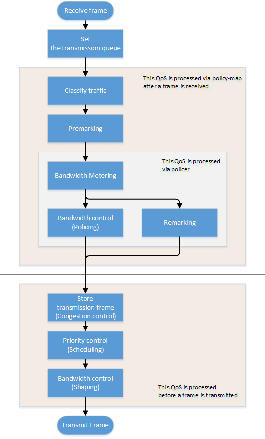
3.3 Transmission queue assignments
When this product receives a frame, it determines the initial value of the transmission queue ID according to the CoS value or DSCP value within the frame and the port priority of the reception port.
Of the factors such as the frame’s CoS value and DSCP value, and the port’s priority order, the port’s trust mode determines which factor will be the basis for determining the transmission queue.
The trust mode can be changed by the qos trust command. The default value (when QoS is enabled) is set to CoS.
The transmission queue is assigned per trust mode, using the following rules.
When trust mode is “CoS”
- When the received frame is a frame with a VLAN tag, the CoS value within the tag is used to determine the transmission queue ID.
- When the received frame is a frame without a VLAN tag, the default CoS that is managed by this product is used to determine the transmission queue ID.
The default setting (when QoS is enabled) and the default CoS are set to “0”. This can be changed using the qos cos command.
- Conversion from the CoS value to the transmission queue ID is performed by the CoS-transmission queue ID conversion table.
One such table is maintained by the system, and with the default settings (when QoS is enabled), the settings are as follows. The setting can be changed using the qos cos-queue command.
CoS value Transmission queue ID Traffic Type 0 2 Best Effort 1 0 Background 2 1 Standard(spare) 3 3 Excellent Effort(Business Critical) 4 4 Controlled Load(Streaming Multimedia) 5 5 Video(Interactive Media) less than 100 msec latency and jitter 6 6 Voice(Interactive Media) less than 10 msec latency and jitter 7 7 Network Control(Reserved Traffic)
When trust mode is “DSCP”
- The DSCP in the IP header is used to determine the transmission queue ID.
- Conversion from the DSCP value to the transmission queue ID is performed by the DSCP-transmission queue ID conversion table.
One such table is maintained by the system, and with the default settings (when QoS is enabled), the settings are as follows. The setting can be changed using the qos dscp-queue command.
DSCP value Transmission queue ID Traffic Type 0 - 7 2 Best Effort 8 -15 0 Background 16 - 23 1 Standard(spare) 24 - 31 3 Excellent Effort(Business Critical) 32 - 39 4 Controlled Load(Streaming Multimedia) 40 - 47 5 Video(Interactive Media) less than 100 msec latency and jitter 48 - 55 6 Voice(Interactive Media) less than 10 msec latency and jitter 56 - 63 7 Network Control(Reserved Traffic)
When trust mode is “port priority”
- The transmission queue ID is determined by the port priority.
- By default (when QoS is enabled), port priority is set to 2. The setting can be changed using the qos port-priority-queue command.
If the trust mode is “CoS” or “DSCP,” the transmission queue ID might be reassigned due to QoS processing (see below) by the policy map.
In this case, the new transmission queue ID is reassigned based on the transmission queue ID conversion table that corresponds to the port’s trust mode.
- Pre-marking
- Refer to “Pre-marking” for details.
- Specify transmission queue
- When the trust mode is “CoS”, specify the CoS value that corresponds to the transmission queue ID, using the set cos-queue command.
- When the trust mode is “DSCP”, specify the DSCP value that corresponds to the transmission queue ID, using the set dscp-queue command.
- Remarking
- Refer to Metering/policing/remarking for details.
If the trust mode is “port priority,” the transmission queue ID cannot be changed by the policy map’s QoS processing. (It is not possible to apply a policy map that includes premarking, transmission queue specification, and remarking settings.)
3.4 Transmission queue assignments (frames sent from the switch itself)
As an exception to the transmission queue assignments, frames sent from the switch itself (CPU) are automatically assigned the transmission queue determined by the system. (They are not given transmission queue assignments based on the trust mode.)
The qos queue sent-from-cpu command can be used to change the transmission queue that is assigned, and by default the transmission queue ID is set to 7.
3.5 Traffic classification
Traffic classification is a function to classify received frames, based on a class map that defines the conditions of the IP header, TCP header, and so on.
The conditions that can be classified and the commands for settings are shown in the table below.
- Conditions that can be classified, and commands for settings
Classification condition Condition-setting command Class map setting mode Number that can be registered per class map Source/destination MAC address access-list
(*Note 3)match access-list 1 Source/destination IP address 1 IP protocol type (*Note 1) 1 Ethernet frame type number match ethertype 1 CoS value for VLAN tag header match cos 8 Precedence value for IP header match ip-precedence 8 DSCP value for IP header match ip-dscp 8 VLAN ID (*Note 2) match vlan, match vlan-range 30 *1: IPv6 is not subject to classification by IP protocol type.
*2: Does not include isolated or community VLANs in a private VLAN.
*3: Up to 39 conditions can be set in the access list for traffic classification.
- Traffic is classified per class map.
- One classification condition type can be set for one class map. Policer-based QoS processing (metering/policing/remarking) and pre-marking, as well as specifying the transmission queue can be done for frames that match the conditions.
- If classification conditions are not specified, all frames are classified into the corresponding traffic class.
- For classification based on CoS, IP precedence, DSCP, and the VLAN ID, multiple classifications can be made for one class map.
- Associating multiple class maps to a policy map will make it possible to classify complex traffic for the receiving port. Up to eight class maps can be associated to one policy map.
- Information for the class map that was set can be confirmed using the show class-map command.
- Information for the policy map that was set can be confirmed using the show policy-map command.
- Use the show qos map-status to check the port to which the policy map is applied, and the policy map to which the class map is associated.
3.6 Pre-marking
Pre-marking is a function to change (assign) the CoS, IP precedence, and DSCP values for received frames classified into traffic classes.
Pre-marking is set using the policy map and class mode settings shown below.
- Pre-marking setting commands
Pre-marking target Command for settings CoS set cos IP Precedence set ip-precedence DSCP set ip-dscp - The DSCP values that can be premarked include the value recommended in the RFC and those not found in the RFC, for a total of four. (This rule also applies to DSCP values that are used in remarking.)
- Only one pre-marking setting can be made for a class map. This cannot be used together when specifying a transmission queue (set cos-queue, set ip-dscp-queue).
- When pre-marking, the transmission queue will be reassigned based on the changed value and the transmission queue ID conversion table that corresponds to the trust mode.
3.7 Metering/policing/remarking
Bandwidth can be controlled by measuring the bandwidth used, and discarding or reprioritizing packets according to the measurement results.
The processing series for metering, policing and remarking is done per “policer”.
- Processing summary for bandwidth control
Process name Summary Metering This measures how much bandwidth is being taken up by the classified traffic based on the traffic rate and burst size, and classifies this into three bandwidth classes (green, yellow and red). Actions such as discarding (policing) and remarking can be specified for each classified bandwidth class.
Policing The bandwidth usage can be kept within a certain amount by discarding frames, using bandwidth class information. Remarking The CoS, IP precedence and DSCP value for a frame can be changed using the bandwidth class information.
Metering, policing, and remarking cannot be performed for the following logical interfaces.
Logical interface grouped across the member switches that make up the stack (green I/F below)
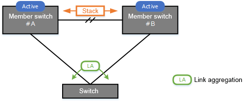
3.7.1 Policer types
There are two types of policers: an individual policer that performs metering/policing/remarking on one traffic class, and an aggregate policer that performs these actions on multiple aggregated traffic classes.
- Individual policer
Metering/policing/remarking is done per traffic class.
To make settings, use the policy map/class mode’s police command and remark-map command.
- Aggregate policer
Metering/policing/remarking is done on multiple traffic classes, which are aggregated.
The aggregate policer can be created using the aggregate-police command, and the content can be specified by the aggregate policer mode’s police command and remark-map command.
To apply a created aggregate policer to a traffic class, use the police-aggregate command.
- The commands used to make settings for an individual policer and an aggregate policer respectively are as follows.
Content of setting Individual policer Aggregate policer Create policer - aggregate-police Set policer (metering/policing/remarking)
police single-rate, police twin-rate (policy map / class mode)
police single-rate, police twin-rate (aggregate policer mode)
Apply policer to traffic class police-aggregate Detailed remarking settings remark-map (policy map / class mode)
remark-map (aggregate policer mode)
3.7.2 Metering settings
There are two types of metering: single rate policy (RFC2697) and twin rate policy (RFC2698).
The type of metering to use and the control parameters are specified using the police command (policy map/class mode or aggregate policer mode).
- Single rate policers (RFC2697)
Single rate policers separate the frames within a traffic class into three bandwidth classes: “green” (conforming), “yellow” (exceeding) or “red” (violating), based on the traffic rate (CIR) and burst size (CBS, EBS).
- Single rate policer control parameters
Parameter Explanation CIR (Committed Information Rate) This is the amount of tokens that is periodically stored in buckets. The amount can be specified in the range of 1–102,300,000 kbps.
CBS (Committed Burst Size) This is the amount of traffic that can be removed at one time from the first token bucket (a conforming token bucket). The amount can be specified in the range of 11–2,097,120 kByte.
EBS (Exceed Burst Size) This is the amount of traffic that can be removed at one time from the second token bucket (an exceeding token bucket). The amount can be specified in the range of 11–2,097,120 kByte.
- Single rate policer control parameters
- Twin rate policer (RFC2698)
Twin rate policers separate the frames within a traffic class into three bandwidth classes: “green” (conforming), “yellow” (exceeding) or “red” (violating), based on the traffic rate (CIR) and burst size (CBS, EBS).
- Twin rate policer control parameters
Parameter Explanation CIR (Committed Information Rate) This is the amount of tokens periodically stored in the second token bucket (confirming token bucket). The amount can be specified in the range of 1–102,300,000 kbps.
PIR (Peak Information Rate) This is the amount of tokens periodically stored in the first token bucket (peak token bucket). The amount can be specified in the range of 1–102,300,000 kbps.
However, a value smaller than the CIR cannot be specified.
CBS (Committed Burst Size) This is the amount of token traffic that can be removed at one time from the conforming token bucket. The amount can be specified in the range of 11–2,097,120 kByte.
PBS (Peak Burst Size) This is the amount of token traffic that can be removed at one time from the peak token bucket. The amount can be specified in the range of 11–2,097,120 kByte.
- Twin rate policer control parameters
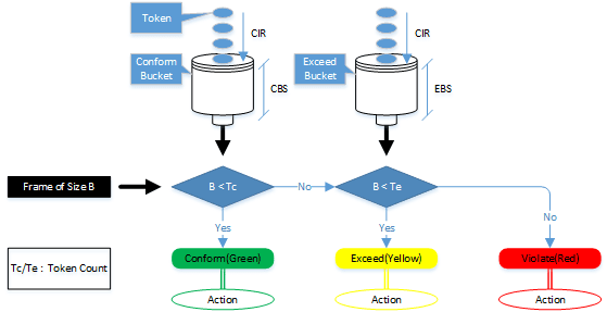
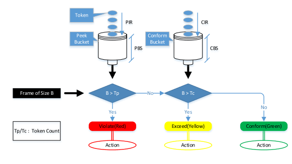
3.7.3 Metering action (policing/remarking) settings
To specify the action for a bandwidth class that was categorized by metering, use the police command (in policy map/class mode or aggregate policer mode).
This product lets you define the following actions for each bandwidth class.
- Specifying bandwidth class actions
Bandwidth class Forward Discard Remark Green ✓ - - Yellow ✓ ✓ ✓ (only one or the other)
Red - ✓ - To make detailed settings for remarking, use the remark-map command (policy map/class mode or aggregate policer mode).
As with pre-marking, remarking to DSCP values can use the value recommended by RFC (refer to separate table 1. “Standard PHB (RFC recommended value)” and up to four others in addition.
When remarking, the transmission queue will be reassigned based on the changed value and the transmission queue ID conversion table that corresponds to the trust mode.
- If metering is not done, all frames that have been classified into traffic classes will be handled as the green bandwidth class.
3.8 Storing in the transmission queue
Frames are stored in the transmission queue that is finally determined through a series of QoS processing.
In order to resolve transmission queue congestion, this product provides a system to select and discard frames.
- Tail drop
This product uses the tail drop method to resolve overflow in the transmission queue.
When the threshold values shown below for the bandwidth class that is classified by metering has been exceeded, the frame in question will be discarded.
Frames discarded by tail drop are counted by the frame counter.
Bandwidth class Tail drop threshold value (%) Green + Yellow 100% Red 60% - Tail drop is disabled only if the stack function is disabled and flow control is enabled.
It is not possible to change the threshold value.
- The extent of the transmission queue congestion can be checked using the show qos queue-counters command.
- The number of packets discarded by tail drop can be checked using the show interface, show frame-counter command.
3.9 Scheduling
Scheduling is used to determine what rules are used to send out the frames that are stored in the transmission queue.
Appropriate control of the scheduling along with the system to control congestion will help ensure QoS. (Inappropriate scheduling will result in degradation of QoS.)
This product supports two types of scheduling for the transmission queue, the strict priority system (SP) and the weighted round-robin (WRR) system.
SP and WRR can also be integrated in the interface and used together. (When doing so, SP will be given priority during processing.)
Strict priority system (SP)
The data with the highest priority in the queue will be transmitted first.
When a frame is stored in a high-priority queue, it can never be transmitted from a lower-priority queue.
Weighted round-robin system (WRR)
A weight is set for each queue, and frames are transmitted based on the ratio. A weight of 1–32 can be set.
Frames can also be transmitted from a lower-priority queue, within a specified percentage.
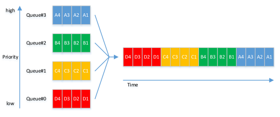
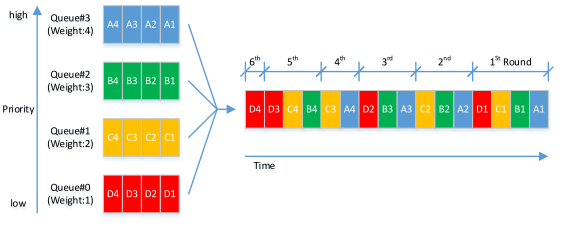
The transmission queue settings are made for the entire system, not for each interface.
Use the qos wrr-weight command to set the weight.
The default setting (when QoS is enabled) and the scheduling setting is “SP” for all queues.
3.10 Shaping
If a frame is forwarded from a broadband network to a narrowband network at the same transmission speed when connecting to a network with different bandwidth, the frame cannot be forwarded, which may result in insufficient bandwidth.
Shaping is a function that monitors the frame transmission speed, and restricts the forwarding rate to a specific amount by temporarily buffering frames with a speed that exceeds the limit, and then transmitting them.
Shaping on this product is realized by using a single token bucket.
- Single token bucket
- Shaping can be specified for individual ports and for individual queues, respectively using the following commands.
Object of shaping Command for settings By port traffic-shape rate By transmission queue traffic-shape queue rate - Specify the upper limit of the transmission rate (CIR) and the burst size (BC).
- The upper limit of the transmission rate (CIR) can be specified from 18–10,000,000 kbps.
- The burst size (BC) can be specified from 16–16,000 kbyte. However, this is specified in 4 Kbyte units.
- Set a burst size value that is 10 times larger than the largest MRU value (largest MRU value for each interface).
- Example: If the largest MRU value is 3,200 bytes, specify a shaping burst size of at least 32 Kbytes (10 x 3,200 bytes).
- Frames are not sent from ports with shaping specified unless an appropriate burst size is specified.
- If shaping is used both by queue and by port, shaping by port is applied after shaping by queue.
- The default setting (when QoS is enabled) and the shaping setting is “disable” for all ports and all queues.
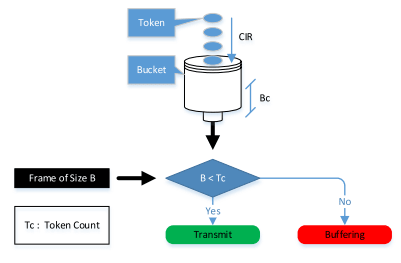
Separate table 1: Standard PHB (RFC recommended value)
Standard PHB (RFC recommended value)
| PHB | DSCP value | RFC | |
|---|---|---|---|
| Default | 0 | RFC2474 | |
| CS (Class Selector) | CS0 | 0 | RFC2474 |
| CS1 | 8 | ||
| CS2 | 16 | ||
| CS3 | 24 | ||
| CS4 | 32 | ||
| CS5 | 40 | ||
| CS6 | 48 | ||
| CS7 | 56 | ||
| AF (Assured Forwarding) | AF11 | 10 | RFC2597 |
| AF12 | 12 | ||
| AF13 | 14 | ||
| AF21 | 18 | ||
| AF22 | 20 | ||
| AF23 | 22 | ||
| AF31 | 26 | ||
| AF32 | 28 | ||
| AF33 | 30 | ||
| AF41 | 34 | ||
| AF42 | 36 | ||
| AF43 | 38 | ||
| EF (Expedited Forwarding) | 46 | RFC2598 | |
4 Related Commands
The related commands are shown below.
For details on the commands, refer to the Command Reference.
QoS-related commands
| Operations | Operating Commands |
|---|---|
| Enable/disable QoS | qos enable |
| Set default CoS | qos cos |
| Change trust mode | qos trust |
| Generate policy map for ingress frames | policy-map |
| Apply policy map for ingress frames | service-policy input |
| Show status of QoS function setting | show qos |
| Show QoS information for LAN/SFP port | show qos interface |
| Show egress queue usage ratio | show qos queue-counters |
| Show policy map information | show policy-map |
| Show map status | show qos map-status |
| Set CoS - transmission queue ID conversion table | qos cos-queue |
| Set DSCP - transmission queue ID conversion table | qos dscp-queue |
| Set port priority order | qos port-priority-queue |
| Set priority order of frames sent from the switch itself | qos queue sent-from-cpu |
| Generate class map (traffic category conditions) | class-map |
| Associate class map | class |
| Set traffic classification conditions (access-group) | match access-list |
| Set traffic classification conditions (CoS) | match cos |
| Set traffic classification conditions (TOS precedence) | match ip-precedence |
| Set traffic classification conditions (DSCP) | match ip-dscp |
| Set traffic classification conditions (Ethernet Type) | match ethertype |
| Set traffic classification conditions (VLAN ID) | match vlan |
| Set traffic classification conditions (VLAN ID range) | match vlan-range |
| Show class map information | show class-map |
| Set pre-marking (CoS) | set cos |
| Set pre-marking (TOS precedence) | set ip-precedence |
| Set pre-marking (DSCP) | set ip-dscp |
| Set individual policer / aggregate policer (single rate) | police signle-rate |
| Set individual policer / aggregate policer (twin rate) | police twin-rate |
| Set remarking for individual policer / aggregate policer | remark-map |
| Create aggregate policer | aggregate-police |
| Show aggregate policer | show aggregate-police |
| Apply aggregate policer | police-aggregate |
| Show metering counter | show qos metering-counters |
| Clear metering counter | clear qos metering-counters |
| Set egress queue (CoS-Queue) | set cos-queue |
| Set egress queue (DSCP-Queue) | set ip-dscp-queue |
| Set egress queue scheduling | qos wrr-weight |
| Set traffic shaping (individual port) | traffic-shape rate |
| Set traffic shaping (individual queue) | traffic-shape queue rate |
5 Examples of Command Execution
5.1 Priority control (SP) using DSCP values
This example allocates the transmission queue based on the DSCP value of the frame, for priority control (SP).
When the DSCP = 56, 46, 8, 0 frame is received, large frames for DSCP values from LAN port #3 will be processed with priority.
- DSCP priority control (SP): setting example
- Prioritizing the input frame is done as follows.
- DSCP = 56 frame is set at priority level 7
- DSCP = 46 frame is set at priority level 5
- DSCP = 8 frame is set at priority level 1
- DSCP = 0 frame is set at priority level 0
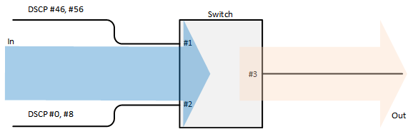
- This sets the trust mode for the reception ports (LAN ports #1 and #2) on which QoS is enabled.
Yamaha(config)#qos enable … (Enable QoS) Yamaha(config)#interface port1.1 … (Settings for LAN port #1) Yamaha(config-if)#qos trust dscp … (Change trust mode to DSCP) Yamaha(config-if)#exit Yamaha(config)#interface port1.2 … (Settings for LAN port #2) Yamaha(config-if)#qos trust dscp … (Change trust mode to DSCP) Yamaha(config-if)#exit
- This sets the DSCP - transmission queue ID conversion table.
As the transmission queue ID corresponding to DSCP value = 46, 56 is the default, there is no need to make this setting, but it is listed for purposes of clarity.
Yamaha(config)#qos dscp-queue 56 7 … (Place frames of DSCP = 56 in transmission queue #7) Yamaha(config)#qos dscp-queue 46 5 … (Place frames of DSCP = 46 in transmission queue #5) Yamaha(config)#qos dscp-queue 8 1 … (Place frames of DSCP = 8 in transmission queue #1) Yamaha(config)#qos dscp-queue 0 0 … (Place frames of DSCP = 0 in transmission queue #0)
- This sets the scheduling method per transmission queue.
As this is the default, there is no need to make this setting, but it is listed for purposes of clarity.
Yamaha(config)# no qos wrr-weight 7 … (Queue:7 SP method) Yamaha(config)# no qos wrr-weight 5 … (Queue:5 SP method) Yamaha(config)# no qos wrr-weight 1 … (Queue:1 SP method) Yamaha(config)# no qos wrr-weight 0 … (Queue:0 SP method)
5.2 Priority control (SP+WRR) using an access list
This example classifies traffic by using the source IP address, and sets the priority control (WRR).
- Priority control (SP+WRR): setting example
- Classification conditions and priority setting for input frames
- The packet from 192.168.10.2 is classified as traffic A, and is set with a priority level of 7 during packet transmission
- The packet from 192.168.20.2 is classified as traffic B, and is set with a priority level of 6 during packet transmission
- The packet from 192.168.30.2 is classified as traffic C, and is set with a priority level of 5 during packet transmission
- The packet from 192.168.40.2 is classified as traffic D, and is set with a priority level of 4 during packet transmission
- The packet from 192.168.50.2 is classified as traffic E, and is set with a priority level of 3 during packet transmission
- The packet from 192.168.60.2 is classified as traffic F, and is set with a priority level of 2 during packet transmission
- The packet from 192.168.70.2 is classified as traffic G, and is set with a priority level of 1 during packet transmission
- The packet from 192.168.80.2 is classified as traffic H, and is set with a priority level of 0 during packet transmission
- Scheduling method
These are the integrated SP and WRR settings to make.
Queue ID Method Weight (%) 7 SP - 6 SP - 5 SP - 4 WRR 8 (40.0%) 3 WRR 6 (30.0%) 2 WRR 3 (15.0%) 1 WRR 2 (10.0%) 0 WRR 1 (5.0%)
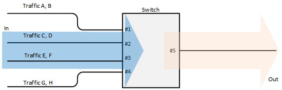
- This enables QoS, defines the access lists for traffic A–H, and defines the traffic classes that will be set in the LAN ports.
Yamaha(config)#qos enable … (Enable QoS) Yamaha(config)#access-list 1 permit any 192.168.10.2 0.0.0.0 any … (Traffic A) Yamaha(config)#class-map cmap-A Yamaha(config-cmap)#match access-list 1 Yamaha(config-cmap)#exit Yamaha(config)#access-list 2 permit any 192.168.20.2 0.0.0.0 any … (Traffic B) Yamaha(config)#class-map cmap-B Yamaha(config-cmap)#match access-list 2 Yamaha(config-cmap)#exit Yamaha(config)#access-list 3 permit any 192.168.30.2 0.0.0.0 any … (Traffic C) Yamaha(config)#class-map cmap-C Yamaha(config-cmap)#match access-list 3 Yamaha(config-cmap)#exit Yamaha(config)#access-list 4 permit any 192.168.40.2 0.0.0.0 any … (Traffic D) Yamaha(config)#class-map cmap-D Yamaha(config-cmap)#match access-list 4 Yamaha(config-cmap)#exit Yamaha(config)#access-list 5 permit any 192.168.50.2 0.0.0.0 any … (Traffic E) Yamaha(config)#class-map cmap-E Yamaha(config-cmap)#match access-list 5 Yamaha(config-cmap)#exit Yamaha(config)#access-list 6 permit any 192.168.60.2 0.0.0.0 any … (Traffic F) Yamaha(config)#class-map cmap-F Yamaha(config-cmap)#match access-list 6 Yamaha(config-cmap)#exit Yamaha(config)#access-list 7 permit any 192.168.70.2 0.0.0.0 any … (Traffic G) Yamaha(config)#class-map cmap-G Yamaha(config-cmap)#match access-list 7 Yamaha(config-cmap)#exit Yamaha(config)#access-list 8 permit any 192.168.80.2 0.0.0.0 any … (Traffic H) Yamaha(config)#class-map cmap-H Yamaha(config-cmap)#match access-list 8 Yamaha(config-cmap)#exit
- This reverts the CoS - transmission queue ID conversion table to the default setting.
Yamaha(config)#no qos cos-queue 0 Yamaha(config)#no qos cos-queue 1 Yamaha(config)#no qos cos-queue 2 Yamaha(config)#no qos cos-queue 3 Yamaha(config)#no qos cos-queue 4 Yamaha(config)#no qos cos-queue 5 Yamaha(config)#no qos cos-queue 6 Yamaha(config)#no qos cos-queue 7
- This generates and applies the policy to LAN port #1 (port1.1).
This sets a transmission queue with CoS value 7 to traffic-A, and a transmission queue with CoS value 6 to traffic-B.
Yamaha(config)#policy-map pmap1 Yamaha(config-pmap)#class cmap-A Yamaha(config-pmap-c)#set cos-queue 7 … (Traffic-A is local priority order 7) Yamaha(config-pmap-c)#exit Yamaha(config-pmap)#class cmap-B Yamaha(config-pmap-c)#set cos-queue 6 … (Traffic-B is local priority order 6) Yamaha(config-pmap-c)#exit Yamaha(config-pmap)#exit Yamaha(config)#interface port1.1 … (LAN port #1) Yamaha(config-if)#service-policy input pmap1 … (Apply policy to received frames) Yamaha(config-if)# exit
- This generates and applies the policy to LAN port #2 (port1.2).
This sets a transmission queue with CoS value 5 to traffic-C, and a transmission queue with CoS value 4 to traffic-D.
Yamaha(config)#policy-map pmap2 Yamaha(config-pmap)#class cmap-C Yamaha(config-pmap-c)#set cos-queue 5 … (Traffic-C is local priority order 5) Yamaha(config-pmap-c)#exit Yamaha(config-pmap)#class cmap-D Yamaha(config-pmap-c)#set cos-queue 4 … (Traffic-D is local priority order 4) Yamaha(config-pmap-c)#exit Yamaha(config-pmap)#exit Yamaha(config)#interface port1.2 … (LAN port #2) Yamaha(config-if)#service-policy input pmap2 … (Apply policy to received frames) Yamaha(config-if)# exit
- This generates and applies the policy to LAN port #3 (port1.3).
This sets a transmission queue with CoS value 3 to traffic-E, and a transmission queue with CoS value 0 to traffic-F.
Yamaha(config)#policy-map pmap3 Yamaha(config-pmap)#class cmap-E Yamaha(config-pmap-c)#set cos-queue 3 … (Traffic-E is local priority order 3) Yamaha(config-pmap-c)#exit Yamaha(config-pmap)#class cmap-F Yamaha(config-pmap-c)#set cos-queue 0 … (Traffic-F is local priority order 2) Yamaha(config-pmap-c)#exit Yamaha(config-pmap)#exit Yamaha(config)#interface port1.3 … (LAN port #3) Yamaha(config-if)#service-policy input pmap3 … (Apply policy to received frames) Yamaha(config-if)# exit
- This generates and applies the policy to LAN port #4 (port1.4).
This sets a transmission queue with CoS value 2 to traffic-G, and a transmission queue with CoS value 1 to traffic-H.
Yamaha(config)#policy-map pmap4 Yamaha(config-pmap)#class cmap-G Yamaha(config-pmap-c)#set cos-queue 2 … (Traffic-G is local priority order 1) Yamaha(config-pmap-c)#exit Yamaha(config-pmap)#class cmap-H Yamaha(config-pmap-c)#set cos-queue 1 … (Traffic-H is local priority order 0) Yamaha(config-pmap-c)#exit Yamaha(config-pmap)#exit Yamaha(config)#interface port1.4 … (LAN port #4) Yamaha(config-if)#service-policy input pmap4 … (Apply policy to received frames) Yamaha(config-if)#exit
- This sets the scheduling method for the transmission queue.
As this queue IDs 5, 6, and 7 are the defaults, there is no need to make this setting, but it is listed for purposes of clarity.
Yamaha(config)#qos wrr-weight 0 1 … (Transmission queue 0: WRR method, weight 1) Yamaha(config)#qos wrr-weight 1 2 … (Transmission queue 1: WRR method, weight 2) Yamaha(config)#qos wrr-weight 2 3 … (Transmission queue 2: WRR method, weight 3) Yamaha(config)#qos wrr-weight 3 6 … (Transmission queue 3: WRR method, weight 6) Yamaha(config)#qos wrr-weight 4 8 … (Transmission queue 4: WRR method, weight 8) Yamaha(config)#no qos wrr-weight 5 … (Transmission queue 5: SP method) Yamaha(config)#no qos wrr-weight 6 … (Transmission queue 6: SP method) Yamaha(config)#no qos wrr-weight 7 … (Transmission queue 7: SP method)
5.3 Priority control using port priority trust mode
The transmission queue is determined according to the port priority order that is specified for each reception port.
- Priority control using port priority: setting example
- Set priority for each reception port
- Set LAN port#1 (port1.1) to priority order 6.
- Set LAN port#2 (port1.2) to priority order 4.
- Set LAN port#3 (port1.3) to priority order 2.
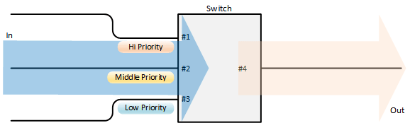
- Enable QoS and set the trust mode for the reception ports (LAN ports #1, #2, and #3).
Yamaha(config)#qos enable … (Enable QoS) Yamaha(config)#interface port1.1 … (Settings for LAN port #1) Yamaha(config-if)#qos trust port-priority … (Change trust mode to “port priority”) Yamaha(config-if)#qos port-priority-queue 6 … (Set port priority order to 6) Yamaha(config-if)#exit Yamaha(config)#interface port1.2 … (Settings for LAN port #2) Yamaha(config-if)#qos trust port-priority … (Change trust mode to “port priority”) Yamaha(config-if)#qos port-priority-queue 4 … (Set port priority order to 4) Yamaha(config-if)#exit Yamaha(config)#interface port1.3 … (Settings for LAN port #3) Yamaha(config-if)#qos trust port-priority … (Change trust mode to “port priority”) Yamaha(config-if)#qos port-priority-queue 2 … (Set port priority order to 2) Yamaha(config-if)#exit
5.4 Bandwidth control using access list (twin rate / individual policer)
This example set bandwidth control by using the source IP address. A twin rate policer and an individual policer are used for metering.
- Bandwidth control: setting example
- Classification conditions and bandwidth limits for input frames
- Packets from 192.168.10.2 are classified as traffic A, and a reception rate (CIR) of 25 Mbps is guaranteed.
- Packets from 192.168.20.2 are classified as traffic B, and a reception rate (CIR) of 15 Mbps is guaranteed.
- Packets from 192.168.30.2 are classified as traffic C, and a reception rate (CIR) of 10 Mbps is guaranteed.
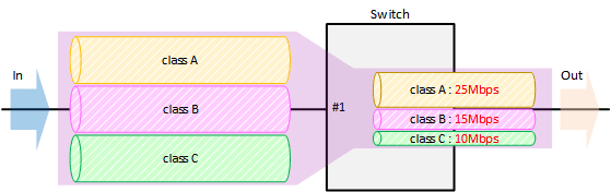
- Enable QoS, define the access lists for traffic A–C, and define the traffic classes that will be set for the LAN ports.
Yamaha(config)#qos enable … (Enable QoS) Yamaha(config)#access-list 1 permit any 192.168.10.2 0.0.0.0 any … (Traffic A) Yamaha(config)#class-map cmap-A Yamaha(config-cmap)#match access-list 1 Yamaha(config-cmap)#exit Yamaha(config)#access-list 2 permit any 192.168.20.2 0.0.0.0 any … (Traffic B) Yamaha(config)#class-map cmap-B Yamaha(config-cmap)#match access-list 2 Yamaha(config-cmap)#exit Yamaha(config)#access-list 3 permit any 192.168.30.2 0.0.0.0 any … (Traffic C) Yamaha(config)#class-map cmap-C Yamaha(config-cmap)#match access-list 3 Yamaha(config-cmap)#exit
- Generate and apply the policy to LAN port #1 (port1.1).
Individually specify metering for traffic A through traffic C.
In the twin rate policer, bandwidth for green can be allocated (guaranteed) by discarding yellow and red.
Yamaha(config)#policy-map pmap1 Yamaha(config-pmap)#class cmap-A … (Set Traffic-A metering) Yamaha(config-pmap-c)#police twin-rate 25000 25000 156 11 yellow-action drop red-action drop Yamaha(config-pmap-c)#exit Yamaha(config-pmap)#class cmap-B … (Set Traffic-B metering) Yamaha(config-pmap-c)#police twin-rate 15000 15000 93 11 yellow-action drop red-action drop Yamaha(config-pmap-c)#exit Yamaha(config-pmap)#class cmap-C … (Set Traffic-C metering) Yamaha(config-pmap-c)#police twin-rate 10000 10000 62 11 yellow-action drop red-action drop Yamaha(config-pmap-c)#exit Yamaha(config-pmap)#exit Yamaha(config)#interface port1.1… (LAN port 1) Yamaha(config-if)#service-policy input pmap1 … (Apply policy to received frames) Yamaha(config-if)#exit
- The metering setting values are shown below.
- Metering type: Twin rate policer
- Traffic-A: CIR, PIR (25,000 kbps), CBS (156 kbyte), PBS (11 kbyte)
- Traffic-B: CIR, PIR (15,000 kbps), CBS (93 kbyte), PBS (11 kbyte)
- Traffic-C: CIR, PIR (10,000 kbps), CBS (62 kbyte), PBS (11 kbyte)
The following calculation is used to find the CBS, with a round-trip time of 0.05 sec.
CBS = CIR (bps) ÷ 8 (bit) × 0.05 (second)
- The metering setting values are shown below.
5.5 Bandwidth control using access list (single rate / aggregate policer)
This example set bandwidth control by using the source IP address. A single rate policer and an aggregate policer are used for metering.
- Bandwidth control: setting example
- Classification conditions and bandwidth limits for input frames
- Packets from 192.168.10.2 are classified as traffic A.
- Packets from 192.168.20.2 are classified as traffic B.
- Packets from 192.168.30.2 are classified as traffic C.
- The reception rate is limited to 25 Mbps for traffic A, B, and C collectively.
- Bandwidth class C “yellow” is remarked as DSCP=0, and sent with low priority.
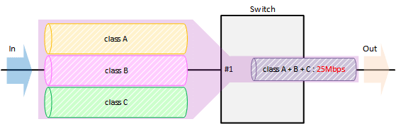
- Enable QoS, define the access lists for traffic A–C, and define the traffic classes that will be set for the LAN ports.
Yamaha(config)#qos enable … (Enable QoS) Yamaha(config)#access-list 1 permit any 192.168.10.2 0.0.0.0 any … (Traffic A) Yamaha(config)#class-map cmap-A Yamaha(config-cmap)#match access-list 1 Yamaha(config-cmap)#exit Yamaha(config)#access-list 2 permit any 192.168.20.2 0.0.0.0 any … (Traffic B) Yamaha(config)#class-map cmap-B Yamaha(config-cmap)#match access-list 2 Yamaha(config-cmap)#exit Yamaha(config)#access-list 3 permit any 192.168.30.2 0.0.0.0 any … (Traffic C) Yamaha(config)#class-map cmap-C Yamaha(config-cmap)#match access-list 3 Yamaha(config-cmap)#exit
- Set the DSCP–transmission queue ID conversion table.
Assign the lowest-priority transmission queue to the DSCP value (0) used for remarking “yellow.”
Yamaha(config)#qos dscp-queue 0 0
- Create an aggregate policer.
Yamaha(config)#aggregate-police agp1 … (Create aggregate policer) Yamaha(config-agg-policer)#police single-rate 25000 156 11 yellow-action remark red-action drop Yamaha(config-agg-policer)#remark-map yellow ip-dscp 0 Yamaha(config-agg-policer)#exit
- The aggregate policer’s metering setting values are as follows.
- Metering type: Single rate policer
- Remark “yellow” to DSCP value = 0
- CIR (25,000 kbps), CBS (156 kbyte), EBS (11 kbyte)
The following calculation is used to find the CBS, with a round-trip time of 0.05 sec.
CBS = CIR (bps) ÷ 8 (bit) × 0.05 (second)
- The aggregate policer’s metering setting values are as follows.
- Generate and apply the policy to LAN port #1 (port1.1).
Specify metering (aggregate policer) for the aggregated traffic of A through C.
Yamaha(config)#policy-map pmap1 Yamaha(config-pmap)#class cmap-A … (Set Traffic-A metering) Yamaha(config-pmap-c)#police-aggregate agp1 Yamaha(config-pmap-c)#exit Yamaha(config-pmap)#class cmap-B … (Set Traffic-B metering) Yamaha(config-pmap-c)#police-aggregate agp1 Yamaha(config-pmap-c)#exit Yamaha(config-pmap)#class cmap-C … (Set Traffic-C metering) Yamaha(config-pmap-c)#police-aggregate agp1 Yamaha(config-pmap-c)#exit Yamaha(config-pmap)#exit Yamaha(config)#interface port1.1… (LAN port 1) Yamaha(config-if)#service-policy input pmap1 … (Apply policy to received frames) Yamaha(config-if)#exit
6 Points of Caution
- LAN/SFP ports that use settings different from those shown below cannot be aggregated as a logical interface.
- Trust mode
- Default CoS
- Port priority
- LAN/SFP ports on which policy maps have been applied cannot belong to a logical interface.
- Policy maps cannot be applied to a LAN/SFP port that belongs to a logical interface. However, if a LAN/SFP port that belongs to a logical interface in startup config has a policy map, the settings for the most recent port number will be applied to the logical interface.
- Fragment packets may not be judged correctly. Specifically, if layer 4 information (source port number, destination port number, and various TCP flags) is included in the conditions, since the information is not included in the second and subsequent fragment packets, correct judgment cannot be made. If there is a possibility of processing fragmented packets, do not include Layer 4 information in the conditions.
7 Related Documentation
None
Flow control
1 Function Overview
A switching hub initially stores received frames in memory and then performs relay processing.
When many frames are sent at the same time and relay processing cannot keep up (a congested state), exceeding the available memory capacity for storage, the frames to be relayed are discarded.
This product includes the following two functions to help mitigate such congestion.
- When ports are operating at full duplex: IEEE 802.3x flow control can be enabled.
- When ports are operating at half duplex: the back pressure function will always be enabled.
2 Definition of Terms Used
- Bit time
- On a 10BASE network, the speed is 10Mbps, so 1 bit time = 100 nsec.
In the same way, the bit time on 100BASE is 10 nsec, and on 1000BASE is 1 nsec.
- Jam signals
In half-duplex communications, where data cannot be transmitted and received at the same time, there is a possibility of data collision. The transmitting device monitors the possibility of data collision during transmission. When possible data collision is detected, the device stops transmitting and sends a jam signal. After the jam signal is sent, the device waits for a random interval before resuming transmission.
Although undefined in IEEE, jam signals that use a 32-digit alternating “1” and “0” bit sequence (such as “10101010101010101010101010101010”) are often used.
3 Function Details
3.1 IEEE 802.3x flow control
For full duplex communication, the MAC control protocol with IEEE802.3x option can be used. The MAC control frame in the diagram below is used for flow control.
MAC control frame
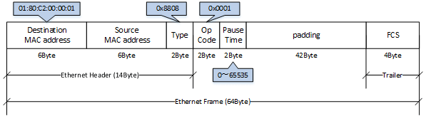
The following flow control operations are performed, based on the restriction start threshold and the restriction cancel threshold.
Flow control: processing flow
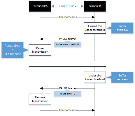
This product can be used for either transmitting or receiving MAC control frames. The operations for each are shown below.
- MAC control frame transmission processing
- Frames are stored in the receive buffer. When the number of frames exceeds the restriction start threshold, a PAUSE frame with a pause time of 65535 is sent.
- When the overflow in the receive buffer is resolved, and the number of frames falls below the restriction cancel threshold, a PAUSE frame with a pause time of 0 is sent.
- MAC control frame reception processing
- When a PAUSE frame with a pause time of 1–65535 is received, the transmission processing will be stopped if the corresponding bit time has elapsed, or if the a PAUSE frame with a pause time of 0 has been received.
Use the flowcontrol command to enable or disable the flow control (when transmitting/receiving MAC control frames).
This setting can be made for the system and for each transmitting/receiving LAN/SFP port, and is set to “disable” by factory default.
In order to enable flow control for an individual port, flow control must be enabled for the system.
The tail drop function is disabled when flow control is enabled in the system, except when the stack function is enabled.
If the Qos function is enabled, flow control cannot be enabled.
When the stack function is enabled, only Pause frames can be received.
3.2 Back pressure
This product sends a jam signal whenever the receiving buffer of a LAN port is about to overflow.
With this, the sender waits for a random amount of time as per the CSMA/CD, and then sends the frames.
When the LAN port is operating at half duplex, the back pressure function will always be enabled.
In addition, when the stack is enabled, jam signals are not sent for communication via the stack port.
Back pressure processing flow
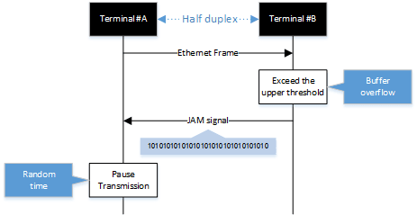
4 Related Commands
The related commands are shown below.
For details, refer to the Command Reference.
List of related commands
| Operations | Operating Commands |
|---|---|
| Set (system) flow control (IEEE 802.3x PAUSE send/receive) | flowcontrol |
| Set (interface) flow control (IEEE 802.3x PAUSE send/receive) | flowcontrol |
| Show flow control operating status | show flowcontrol |
5 Examples of Command Execution
- Enable flow control on LAN port #1.
After the function is enabled, check the flow control operating status.
Yamaha(config)#flowcontrol enable Yamaha(config)#interface port1.1 Yamaha(config-if)#flowcontrol both Yamaha(config-if)#end Yamaha#show flowcontrol port1.1 Port FlowControl RxPause TxPause --------- ----------- ------- ------- port1.1 Both 0 64
6 Points of Caution
None
7 Related Documentation
None
Storm control
1 Function Overview
This product provides a storm control function as a countermeasure against L2 loops and DoS attacks.
Broadcasts, multicasts, and unicast (dlf) frames that are addressed to an unknown host are monitored for each LAN/SFP port, and frames that exceed a preset threshold value are discarded.
This prevents such frames from taking up bandwidth on the LAN/SFP port.
Using this along with the proprietary loop detection and storm control functions enhances the precision of loop detection (avoiding such frames in the first place).
2 Definition of Terms Used
- Broadcast storm/multicast storm
This means a situation where frames addressed for broadcast or multicast are continuously forwarded.
In this situation, the switch floods all ports except for the reception port with the broadcast or multicast.
When this is received by another switch, all ports except for the reception port are flooded in the same way.
When this continues, it can lead to the following symptoms.
- Bandwidth is taken up by the broadcast storm/multicast storm
- The switch’s CPU load increases, making normal operations difficult
- Devices connected to the switch become unable to communicate
- Unicast stream
This means a situation where frames addressed to an unknown unicast destination (dlf: Destination Lookup Failure) are continuously forwarded.
When the MAC address of the receiving device has not been registered in the ARP table, all ports on the switch except for the reception port are flooded.
This leads to the same symptoms occurring as with a broadcast storm or multicast storm.
3 Function Details
The operating specifications for storm control are shown below.
- The storm control function can be enabled for LAN/SFP ports.
The setting is disabled for all ports by default.
- Storm control on this product can be specified as a tolerance percentage for the bandwidth of the LAN/SFP ports that receive broadcast frames, multicast frames, and frames addressed to an unknown unicast destination.
(Control can be made in two decimal points. Specifying 100% is the same as disabling the storm function.)
The bandwidth tolerance is common for all frames, and the user can select the applicable frames.
The settings are made using the storm-control command.
- The following SYSLOG will be outputted at the time that storm control is enabled or disabled.
- When enabled: [ STORM]:inf: storm-control ENABLE (port:port1.1, type:B M U, level:50. 0%)
- When disabled: [ STORM]:inf: storm-control DISABLE (port:port1.1)
- When frames are received that exceeds the permitted bandwidth, the excessive frames are discarded.
- Use the show storm-control command to check the storm control information set for the LAN/SFP port.
4 Related Commands
The related commands are shown below.
For details on the commands, refer to the Command Reference.
List of related commands
| Operations | Operating Commands |
|---|---|
| Set storm control | storm-control |
| Show storm control reception upper limit | show storm-control |
5 Examples of Command Execution
In this example, the receivable L2 broadcast packets for LAN port 1 are restricted to a port bandwidth of 30%.
Storm control command setting: example
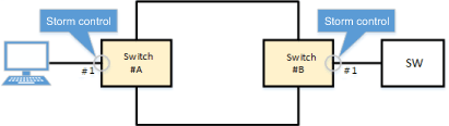
Yamaha(config)#interface port1.1 Yamaha(config-if)#storm-control broadcast level 30 … (Limit broadcast to 30% of bandwidth) Yamaha(config-if)#end Yamaha# Yamaha#show storm-control Port BcastLevel McastLevel UcastLevel port1.1 30.00% 100.00% 100.00% port1.2 100.00% 100.00% 100.00% port1.3 100.00% 100.00% 100.00% port1.4 100.00% 100.00% 100.00% port1.5 100.00% 100.00% 100.00% port1.6 100.00% 100.00% 100.00% port1.7 100.00% 100.00% 100.00% port1.8 100.00% 100.00% 100.00% port1.9 100.00% 100.00% 100.00%
6 Points of Caution
None
7 Related Documentation
- L2 switching functions: Proprietary loop detection
- SWX3220 Series Technical Data (Basic Functions)
- AP layer function
DHCP server
1 Function Overview
The DHCP server function assigns (leases) IPv4 addresses to DHCP clients.
Optionally, it can also provide notification of default gateway, DNS server, and other information.
2 Definition of Terms Used
None
3 Function Details
The operating specifications for the DHCP server function are indicated below.
- In addition to enabling/disabling the function for the entire system, the DHCP server function on this product can also enable/disable the function for each interface.
To activate the DHCP server function at an interface, the setting must be enabled for the entire system.- To activate it for the entire system, use the dhcp-server command in the global configuration mode.
- To activate it for a specific interface, use the dhcp-server command in the corresponding interface mode.
- The default settings for the DHCP server function are indicated below. (The function is disabled in default settings.)
- System-wide setting: Disabled
- Interface setting: Disabled
- Set the DHCP server function interface settings with respect to the VLAN interface.
- Use the dhcp-server command to specify settings.
- An IPv4 address must be specified for the VLAN interface.
- The default settings are disabled.
- To assign IP addresses using the DHCP server function, the DHCP pool settings described below must be specified appropriately.
- A maximum of 32 VLAN interfaces can be specified.
- The information distributed to DHCP clients is decided by the DHCP pool.
- Use the dhcp pool command to switch to the DHCP mode and then create the DHCP pool.
- A maximum of 64 DHCP pools can be created.
- The following settings can be specified for DHCP pools.
- Specify the network portion
- Range of IP addresses to assign to clients
- IP addresses to assign to specific clients
- Lease period
- Check for conflicts in IP addresses to be leased
- Default gateway address
- DNS server
- Domain name
- Boot file name
- Server where boot file resides
- User-defined DHCP options
The IP address setting to be assigned as the network portion must be specified if addresses are to be dynamic assigned by the DHCP server.
Multiple pools with the same network portion cannot be specified.
- Assign IP addresses within the network specified for the DHCP pool.
Specify the network portion of DHCP pools as indicated below.- If a DHCP client exists on the same network as a VLAN interface with the DHCP server function enabled, then specify the network for the IP address specified for the VLAN interface.
- If a DHCP client request is received via DHCP relay agent, specify the network to which the client is associated.
- When the DHCP server finishes starting up, the follow log event is output at the debug level.
- “DHCPv4 server started up using the new config”
- The following can be used for user-defined DHCP options.
- Options can be defined using the option command.
Option No. Option Name Mnemonics Available for Commands Form of Option 1 Subnet Mask subnet_mask IP address 2 Time Offset time_offset 4-octet integer 3 Router router IP address sequence 4 Time Server time_server IP address sequence 5 Name Server name_server IP address sequence 6 Domain Name Server dns IP address sequence 7 Log Server log_server IP address sequence 8 Cookie Server cookie_server IP address sequence 9 LPR Server lpr_server IP address sequence 10 Impress Server impress_server IP address sequence 11 Resource Location Server resource_location_server IP address sequence 12 Host Name hostname Character string 13 Boot File Size boot_file_size 2-octet integer 14 Merit Dump File merit_dump_file Character string 15 Domain Name domain Character string 16 Swap Server swap_server IP address 17 Root Path root_path Character string 18 Extensions Pathname extensions_pathname Character string 19 IP Forwarding ip_forwarding Switch 20 Non-Local Source Routing non_local_source_routing Switch 21 Policy Filter policy_filter IP address sequence (formed by combining IP addresses and masks, it must include an even number of IP addresses) 22 Maximum Datagram Reassembly maximum_datagram_reassembly 2-octet integer 23 Default IP TTL default_ip_ttl 1-octet integer 24 Path MTU Aging Timeout path_mtu_aging_timeout 4-octet integer 25 Path MTU Plateau Table path_mtu_plateau_table 2-octet integer sequence 26 Interface MTU interface_mtu 2-octet integer 27 All Subnets are Local all_subnets_are_local Switch 28 Broadcast Address broadcast_address IP address 29 Perform Mask Discovery perform_mask_discovery Switch 30 Mask Supplier mask_supplier Switch 31 Perform Router Discovery perform_router_discovery Switch 32 Router Solicitation Address router_solicitation_address IP address 33 Static Route static_route IP address sequence (formed by combining destination and router addresses, it must include an even number of IP addresses) 34 Trailer Encapsulation trailer_encapsulation Switch 35 Arp Cache Timeout arp_cache_timeout 4-octet integer 36 Ethernet Encapsulation ethernet_encapsulation Switch 37 TCP Default TTL tcp_default_ttl 1-octet integer 38 TCP Keepalive Interval tcp_keepalive_interval 4-octet integer 39 TCP Keepalive Garabage tcp_keepalive_garbage Switch 40 NIS Domain nis_domain Character string 41 NIS Server nis_server IP address sequence 42 NTP Server ntp_server IP address sequence 44 WINS Server wins_server IP address sequence 45 NBT-DD Server nbt_dd_server IP address sequence 46 NBT Node Type nbt_node_type 1-octet integer 47 NBT Scope nbt_scope Character string 48 X Font Server x_font_server IP address sequence 49 X Display Manager x_display_manager IP address sequence 62 Netware/IP Domain Name netware_domain_name Character string 64 NIS+ Domain nis+_domain Character string 65 NIS+ Server nis+_server IP address sequence 66 TFTP Server Name tftp_server_name Character string 67 Boot File Name boot_file_name Character string 68 Mobile IP Home Agent mobile_ip_home_agent IP address sequence 69 SMTP Server smtp_server IP address sequence 70 POP3 Server pop3_server IP address sequence 71 NNTP Server nntp_server IP address sequence 72 Default WWW Server default_www_server IP address sequence 73 Default Finger Server default_finger_server IP address sequence 74 Default IRC Server default_irc_server IP address sequence 75 StreetTalk Server streettalk_server IP address sequence 76 StreetTalk Directory Assistance Server streettalk_directory_assistance_server IP address sequence 85 NDS Server nds_server IP address sequence 86 NDS Tree Name nds_tree_name Character string 87 NDS Context nds_context Character string
- Options can be defined using the option command.
4 Related Commands
Related commands are indicated below.
For details on the commands, refer to the Command Reference.
List of related commands
| Operations | Operating Commands |
|---|---|
| Sets DHCP server function (system) | dhcp-server |
| Sets DHCP server function (interface) | dhcp-server |
| Sets DHCP server action type | server-type |
| Sets DHCP pool | dhcp pool |
| Sets network portion | network |
| Sets range for assigning IP addresses | range |
| Sets IP addresses for assigning to specific clients | bind host |
| Sets lease period | lease |
| Sets checking leased IP address conflicts | probe |
| Sets timeout for checking leased IP address conflicts | probe timeout |
| Sets default gateway address notification | default-router |
| Sets DNS server notification | dns-server |
| Sets domain name notification | domain-name |
| Sets boot file name | bootfile |
| Sets boot file host server | next-server |
| Sets user-defined DHCP option | option |
| Displays DHCP pool information | show dhcp pool |
| Displays DHCP client IP address assignment information | show dhcp binding |
| Displays DHCP server status | show dhcp server |
| Deletes DHCP server lease information | clear dhcp-server lease |
5 Examples of Command Execution
5.1 DHCP Server Settings
The following describes enabling DHCP server operation on vlan1.
It assumes the DHCP client resides on the same network as the VLAN interface.
The IP address for vlan1 is 192.168.100.240/24 and the range of assigned addresses is from 192.168.100.2 to 192.168.100.191/24.
- Set the IP address for vlan1 to 192.168.100.240/24.
Yamaha(config)# interface vlan1 Yamaha(config-if)# ip address 192.168.100.240/24
- Create the DHCP pool "pool_vlan1”.
Yamaha(config)# dhcp pool pool_vlan1 Yamaha(config-dhcp)# ... (Switch to DHCP mode)
- Specify the vlan1 network portion 192.168.100.0/24 in the DHCP pool.
Yamaha(config-dhcp)# network 192.168.100.0/24
- Specify the address assignment range from 192.168.100.2 to 192.168.100.191 in the DHCP pool.
Yamaha(config-dhcp)# range 192.168.100.2 192.168.100.191
- Specify the default gateway to be notified in DHCP option settings and specify the DNS server in the DHCP pool.
Yamaha(config-dhcp)# default-router 192.168.100.240 ... (Default gateway address is 192.168.100.240 (itself)) Yamaha(config-dhcp)# dns-server 192.168.100.1 ... (DNS server address is 192.168.100.1)
- Activate the DHCP server function for vlan1.
Yamaha(config-dhcp)# exit ... (End DHCP mode) Yamaha(config)# interface vlan1 ... (Switch to vlan1 interface mode) Yamaha(config-if)# dhcp-server enable ... (Enable the DHCP server functionality for the interface)
- Activate the DHCP server function for the entire system.
Yamaha(config-dhcp)# exit ... (End interface mode) Yamaha(config)# dhcp-server enable ... (Enable DHCP server functionality for entire system)
6 Points of Caution
- If the alias IP address function is used, then DHCP server cannot assign segment addresses for secondary IP addresses.
7 Related Documentation
DHCP relay
1 Function Overview
The DHCP relay agent function relays DHCP packets to the specified DHCP server.
2 Definition of Terms Used
None
3 Function Details
The operating specifications for the DHCP relay agent function are indicated below.
- In addition to enabling/disabling the function for the entire system, the DHCP relay agent function on this product also enables different relay destinations to be specified for each interface.
To activate the DHCP relay agent function at an interface, the system-wide settings must be enabled.- To specify system-wide settings, use the dhcp-relay command in global configuration mode.
- To specify relay destination settings, use the dhcp-relay server-address command in the corresponding interface mode.
- The default settings for the DHCP relay agent function are indicated below. (The function is disabled in default settings.)
- System-wide setting: Disabled
- Destination setting: None
- Set the relay destination setting with respect to the VLAN interface.
- Use the dhcp-relay server-address command to specify settings.
- DHCP packets received at the specified VLAN interface are relayed to the specified IPv4 address.
- An IPv4 address must be specified for the VLAN interface.
- A maximum of 32 VLAN interfaces can be specified.
- A broadcast address can be specified as the relay destination.
- Then DHCP packets are relayed to the broadcast address in the following cases,
where the destination MAC address is “ff.ff.ff.ff.ff.ff”.- The dhcp-relay broadcast command setting is enabled.
- The broadcast address is specified in the dhcp-relay server-address command.
- Specify the address for the network directly connected to this product as the broadcast address.
- Specifically, specify the network indicated as “directly connected” by the show ip route command.
- For example, given the network address destination 192.168.200.0/24, set the broadcast address to 192.168.200.255.
- The function will operate similarly even if 192.168.200.0 (network address) is specified rather than 192.168.200.255.
- Only a directed broadcast address can be specified as the broadcast address.
A limited broadcast address (255.255.255.255, 0.0.0.0) cannot be specified.
4 Related Commands
The related commands are shown below.
For details on the commands, refer to the Command Reference.
List of related commands| Operations | Operating Commands |
|---|---|
| Sets the DHCP relay agent function | dhcp-relay |
| Sets the relay destination address for the DHCP relay agent function | dhcp-relay server-address |
| Sets relaying packets to the broadcast address for the DHCP relay agent function | dhcp-relay broadcast |
| Displays the DHCP relay agent status | show dhcp relay |
5 Examples of Command Execution
5.1 Setting the DHCP Relay Agent Function
Enable the DHCP relay agent for vlan1.
Relay DHCP packets received from DHCP clients by vlan1 to the DHCP server existing on the vlan2 network.
Set the IP address to 192.168.100.240/24 for vlan1, 192.168.200.240/24 for vlan2, and 192.168.200.1 for the DHCP server.
Associate vlan2 to port 1.2.
- Set the IP address for vlan1 to 192.168.100.240/24.
Yamaha(config)# interface vlan1 Yamaha(config-if)# ip address 192.168.100.240/24
- Create vlan2.
SWX3200(config)#vlan database SWX3200(config-vlan)#vlan 2
- Set the IP address for vlan2 to 192.168.200.240/24.
Yamaha(config)# interface vlan2 Yamaha(config-if)# ip address 192.168.200.240/24
- Set port 1.2 as the access port and associate it with vlan2.
Yamaha(config)# interface port1.2 Yamaha(config-if)# switchport access vlan 2
- Use vlan1 to specify the relay destination address. Specify the DHCP server address.
Yamaha(config)# interface vlan1 Yamaha(config-if)# dhcp-relay server-address 192.168.200.1
- Enable the DHCP relay agent function for the entire system.
Yamaha(config-dhcp)# exit ... (End interface mode) Yamaha(config)# dhcp-relay enable ... (Enable DHCP server functionality for entire system)
6 Points of Caution
- The VLAN specified by the dhcp-relay server-address command must be different than the VLAN specified as the DHCP packet relay destination. Do not specify the dhcp-relay server-address command for the VLAN specified as the relay destination for DHCP packets.
- If the alias IP address function is used, the DHCP relay does not relay packets to the segment address in the secondary IP address.
7 Related Documentation
None
DNS relay
1 Function Overview
The DNS Relay function forwards DNS packets to the specified DNS server.
The DNS Relay function in this product includes cache memory so that it can respond directly to repeated requests without interrupting higher-level servers.
2 Definition of Terms Used
None
3 Function Details
The operating specifications for the DNS Relay function are indicated below.
- In addition to enabling/disabling the function for the entire system, the DNS Relay function in this product can also enable/disable the function for each interface.
To activate the DNS Relay function at an interface, the setting must be enabled for the entire system.- Settings for the entire system are specified using the dns-forwarding command in the global configuration mode.
- To specify settings for a specific interface, use the dns-forwarding command in the corresponding interface mode.
- The default settings for the DNS Relay function are indicated below. (The function will not function with default settings.)
- System-wide setting: Disabled
- Interface setting: Disabled
- Set DNS Relay function interface settings with respect to the VLAN interface.
- An IPv4 address must be specified for the VLAN interface.
- Use the dns-forwarding command to set the address.
- The default settings are disabled.
- DNS packets received at the enabled VLAN interface are forwarded to the specified address by the dns-forwarding name-server command.
- DNS packets that use IPv6 are not forwarded.
- The designation DNS server is specified by the dns-forwarding name-server command.
- If a domain name is specified, queries for that domain name are only forwarded to the specified server.
- An IPv6 address cannot be specified as a forward destination.
- Up to eight DNS servers can be specified.
- Relayed DNS packets are cached.
- DNS packets remaining in cache memory result in returning the content of cache entries, without forwarding them to the server.
- The TTL notice from the destination server is used for cache entry TTL values.
- The maximum TTL value for cache entries can be specified using the dns-forwarding cache max-ttl command.
- If the TTL value notified by the destination server is higher the setting value for this command, then the command setting value is used as the cache entry TTL value.
- A minimum of 500 A-records can be registered in cache.
- The show dns-forwarding cache command displays the cache content.
- A maximum of 1000 cache records can be displayed.
- Static records can be specified.
- Use the dns-forwarding static-host command.
- IPv4 addresses can be linked to a host name.
- If a query is received regarding a host name or address specified by the dns-forwarding static-host command, then the command setting value is returned without forwarding packets to the server.
- Up to 16 static records can be specified.
4 Related Commands
Related commands are indicated below.
For details on the commands, refer to the Command Reference.
List of related commands
| Operations | Operating Commands |
|---|---|
| Enables the DNS relay function (system) | dns-forwarding |
| Enables the DNS relay function (interface) | dns-forwarding |
| Sets the relay destination address for the DNS relay function | dns-forwarding name-server |
| Sets the maximum TTL value for DNS relay function cache entries | dns-forwarding cache max-ttl |
| Deletes DNS relay function cache entries | clear dns-forwarding cache |
| Sets static records for the DNS relay function | dns-forwarding static-host |
| Displays the DNS relay status | show dns-forwarding |
| Displays the DNS relay cache | show dns-forwarding cache |
5 Examples of Command Execution
5.1 DNS Relay Settings
Enable the DNS Relay function for vlan1.
Relay DNS packets received from DNS clients by vlan1 to the DNS server existing on the vlan2 network.
Set the IP address to 192.168.100.240/24 for vlan1, 192.168.200.240/24 for vlan2, and 192.168.200.1 for the DNS server.
Associate vlan2 to port 1.2.
- Sets the forward destination address for the DNS Relay function to 192.168.200.1.
Yamaha(config)# dns-forwarding name-server 192.168.200.1
- Set the IP address for vlan1 to 192.168.100.240/24.
Yamaha(config)# interface vlan1 Yamaha(config-if)# ip address 192.168.100.240/24
- Create vlan2.
Yamaha(config)#vlan database Yamaha(config-vlan)#vlan 2
- Set the IP address for vlan2 to 192.168.200.240/24.
Yamaha(config)# interface vlan2 Yamaha(config-if)# ip address 192.168.200.240/24
- Set port 1.2 as the access port and associate it with vlan2.
Yamaha(config)# interface port1.2 Yamaha(config-if)# switchport access vlan 2
- Enable DNS Relay for vlan1.
Yamaha(config)# interface vlan1 Yamaha(config-if)# dns-forwarding enable
- Activate the DNS Relay function for the entire system.
Yamaha(config-if)# exit Yamaha(config)# dns-forwarding enable
6 Points of Caution
- Requests to the DNS server after repeatedly failing to resolve the DNS name, due to a network interruption or other reason, will return an error without sending a query to the DNS server.
- The packets are eventually forwarded when a normal connection is restored, but it may take a long time before they are forwarded.
- If a domain name is not specified, then all domain DNS requests will send a query to the specified server. That means local networks might repeatedly fail to resolve the name.
- To resolve a local domain name held in an internal company server, for example, specify the server for the domain name, as shown below.
dns-forwarding name-server 192.168.100.1 example.com
- To resolve a local domain name held in an internal company server, for example, specify the server for the domain name, as shown below.
7 Related Documentation
None
RADIUS server
1 Function Overview
The RADIUS server function manages user information and certificates, and performs authentication based on information notified from the client.
By combining with MAC authentication, 802.1X authentication, and Web authentication of this device, the authentication function can be realized with this device alone.
Also, when authenticating with a device other than this device, this device can be operated as an authentication server.
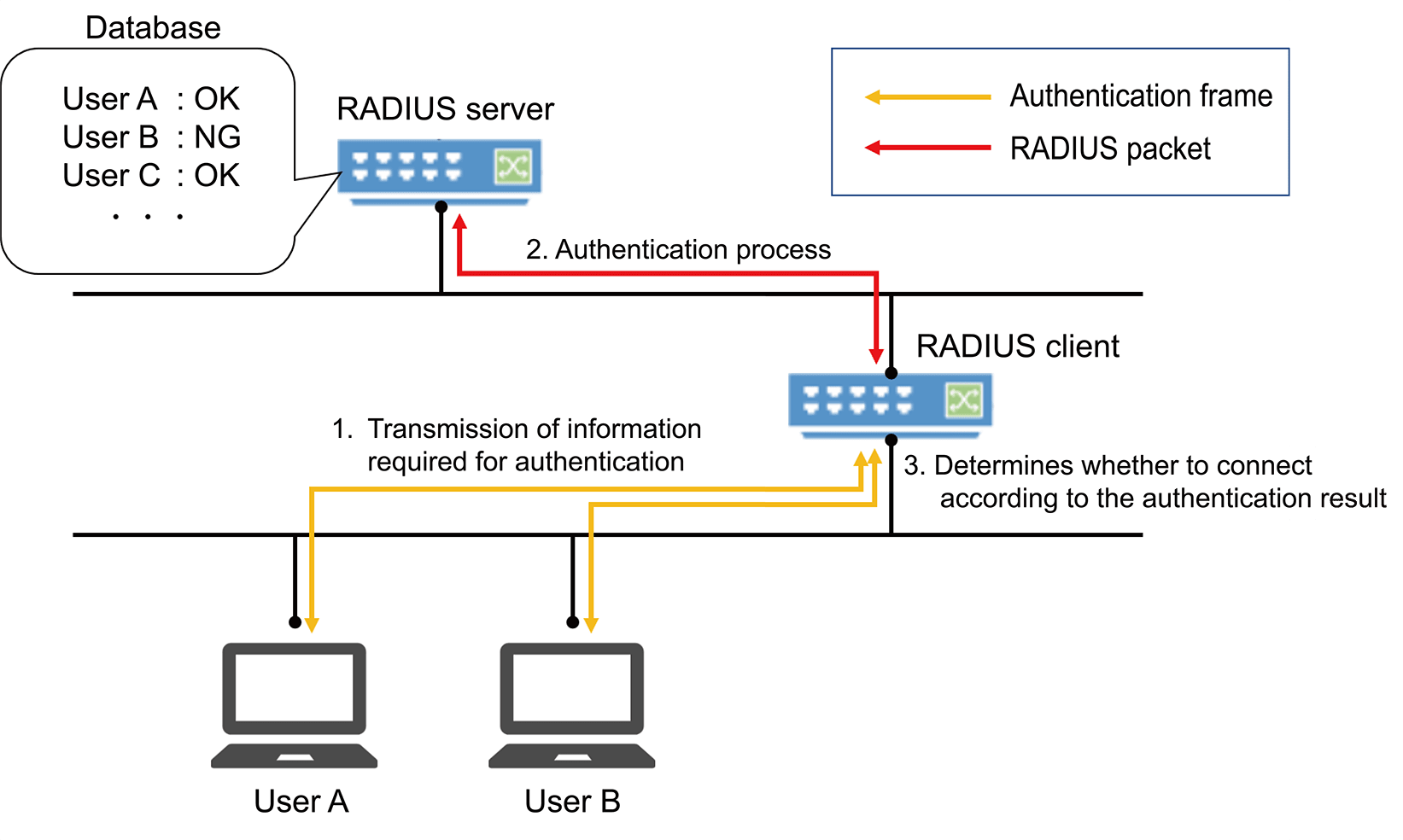
The basic performance of the RADIUS server function and the corresponding authentication method are as follows.
Basic performance
| Item | Performance |
|---|---|
| Number of RADIUS clients that can be registered | 100 |
| Number of users that can be registered | 2000 |
| Key strength | 2048 bit |
| Signature algorithm | SHA256 |
| Certificate Authority name (default value) | YAMAHA_SWITCH |
Supported authentication methods
| Authentication method | Application |
|---|---|
| PAP | MAC authentication |
| EAP-MD5 | IEEE802.1X authentication, MAC authentication, WEB authentication |
| EAP-TLS | IEEE802.1X authentication |
| EAP-TTLS | IEEE802.1X authentication |
| PEAP | IEEE802.1X authentication |
2 Definition of Terms Used
- PKI (Public Key Infrastructure)
Public key infrastructure. Includes digital certificates and certificate authorities (CAs) using public key cryptography.
- Certificate Authority (CA)
An organization that guarantees reliability. It is divided into a root Certificate Authority and an intermediate Certificate Authority.
It has a tree structure with the root Certificate Authority at the top and an intermediate Certificate Authority under it.- Intermediate Certificate Authority
Among Certificate Authorities (CAs), indicates a Certificate Authority whose reliability is guaranteed by a higher-level Certificate Authority (CA).
- Root Certificate Authority
Among Certificate Authorities (CA), indicates a Certificate Authority whose reliability is guaranteed by itself.
- Root Certificate Authority certificate
A public key certificate that has the same issuer and subject and has signed its own public key with its own private key. It is the root of a tree-structured certificate.
- Digital certificate
Data that certifies that the public key issued by the Certificate Authority is the genuine issuer’s public key.
When the issuer makes a certificate request to the Certificate Authority (CA) together with the public key, the Certificate Authority (CA) issues a digital certificate after scrutinizing and confirming it.- EAP-MD5 authentication method (Message digest algorithm 5)
This is an authentication method that uses a user name and password. Authenticates by exchanging an MD5 hash value instead of a plain text password.
- EAP-TLS authentication method (Transport Layer Security)
An authentication method used in IEEE 802.1X, a type of EAP implementation that authenticates by exchanging digital certificates after encrypting the transport layer between the user and the RADIUS server, instead of authenticating with a user ID and password. This is defined in RFC2716 and RFC5216.
- EAP-TTLS authentication method (Tunneled TLS)
An authentication method used in IEEE 802.1X, a type of EAP implementation that establishes a TLS communication channel using the server’s digital certificate and authenticates the user with a password within the encrypted channel. This is defined in RFC5281.
- PEAP authentication method (Protected EAP)
The operating principle is the same as EAP-TTLS (there is only a difference in the protocol in the encrypted tunnel). A TLS communication channel is established using the server’s digital certificate, and the user is authenticated with a password in the encrypted communication channel.
- It is trusted
A certificate indicating that the public key belongs to the issuer has been issued by a trusted third party.
- RADIUS server
The host device that provides the RADIUS server function, in this case, this device.
Authenticates connected users via a RADIUS server and manages authentication/authorization information such as user IDs, passwords, MAC addresses, and associated VLANs.- Server certificate
A certificate to state that the Certificate Authority (CA) has proved that the RADIUS server is trusted.
- RADIUS client
Also called a NAS or an authenticator, it relays between the user connected to the LAN/SFP port and the authentication server, and controls access to the LAN based on the success or failure of authentication.
- User
A device that connects to a RADIUS client and requests authentication, or a supplicant that is software.
It is the minimum unit for identifying the person to be authenticated. There are data required for authentication and authorization, such as a unique user ID and password.- Client certificate (user certificate)
This certificate proves that the user described above is trusted by the Certificate Authority (CA).
3 Function Details
3-1 Root Certificate Authority
To use the RADIUS server function, you must first create a root Certificate Authority.
The root Certificate Authority is used for issuing and managing digital certificates. It can be created with the crypto pki generate ca command.
The Certificate Authority name can be specified in the crypto pki generate ca command argument, if omitted it becomes YAMAHA_SWITCH.
The following certificates are issued and managed based on the root Certificate Authority.
All certificates have a key strength of 2048 bits and a signature algorithm of SHA256.
| Root Certificate Authority certificate | Proves that this device is a trusted root Certificate Authority. Issued at the same time that the root Certificate Authority is created. |
| Server certificate | Proves that this device is a trusted server. Issued at the same time that the root Certificate Authority is created. |
| Client (user) certificate | Proves that the user is trusted. |
| Client revocation certificate | Proves that the client certificate has been revoked. |
The root Certificate Authority is deleted or overwritten by the following operations.
- It is deleted when the cold start command is executed.
- It is deleted when the no crypto pki generate ca command is executed.
- It is deleted when the stack enable command is executed.
- It is deleted when the stack disable command is executed.
- It is deleted when the erase startup-config command is executed.
- It is overwritten when the crypto pki generate ca command is executed again.
- It is overwritten when the restore system command is executed.
- It is overwritten when the copy radius-server local command is executed.
It is necessary to keep the root Certificate Authority installed first consistent, so be careful not to delete it carelessly.
Also, please take measures to back up the file in advance, in case it is deleted.
Once the root CA is deleted, even if the same CA name is set, it will be a different CA from before.
If you delete the root Certificate Authority before backup, you cannot add or revoke the certificate after that. You will have to reissue all the certificates from the beginning.
When the root certificate authority is created by the crypto pki generate ca command, it is automatically saved in the internal area, so there is no need to execute the write command.
3-2 RADIUS client settings
Use the nas command to specify the RADIUS clients that are allowed to access the RADIUS server.
You can specify an individual IP address or network address, and up to 100 addresses can be set.
RADIUS client functionality is verified using the following products.
- Yamaha switch (SWX series)
- Yamaha router (RTX series or NVR series)
- Yamaha wireless access point (WLX series)
The settings of the RADIUS client set by the nas command are not displayed in the config by show running-config.
There is no need to execute the write command because it is automatically saved in a different area from the config, but it is necessary to execute the radius-server local refresh command to reflect it in the actual operation.
Use the show radius-server local nas command to confirm the settings.
3-3 User registration
User information for authentication is registered with the user command.
Up to 2000 user information can be registered.
Items that can be set with the user command are as follows.
| Type | Item | Summary/Remarks |
|---|---|---|
| Mandatory | User ID | ID for uniquely identifying user information |
| Password | Password used in combination with user ID If the client certificate is compressed, use this password for decompression. | |
| Option | User name | Any character string can be set for user identification. |
| MAC address | Compared when the RADIUS client notifies the Calling-Station-Id, and if it does not match, it is not authenticated. | |
| SSID | Compared when the RADIUS client notifies the Called-Station-Id, and if it does not match, it is not authenticated. | |
| Mail address | This is the address for sending the certificate by email. | |
| Authentication method | The default is EAP-TLS, so you must specify it if you want to use another authentication method. | |
| Period of certificate validity | This is valid only when the authentication method is EAP-TLS. If omitted, it will be 23:59:59 on December 31, 2037. | |
| Dynamic VLAN-ID | Specify when using the dynamic VLAN function. |
The user settings set by the user command are not displayed in the config by show running-config etc.
There is no need to execute the write command because it is automatically saved in a different area from the configuration, but it is necessary to execute the radius-server local refresh command to reflect it in the actual operation.
Use the show radius-server local user command to confirm the settings.
3-4 Restricting the authentication method
The authentication method can be restricted by the authentication command.
The authentication method is not restricted by default, but you can use it when you want to temporarily disable a specific authentication method.
3-5 Enabling the RADIUS server function
To enable the RADIUS server function, use the radius-server local enable command.
Set the RADIUS client and user information, and enable the RADIUS server function after the necessary preparations are completed.
3-6 Reflecting settings in operation
If you add/change/delete the settings related to the RADIUS server, execute the radius-server local refresh command to reflect them in actual operation.
The commands reflected in the actual operation by the radius-server local refresh command are as follows.
- authentication command
- nas command
- reauth interval command
- user command
When you add/change/delete settings related to the RADIUS server in Web GUI, processing equivalent to the radius-server local refresh command is automatically performed.
3-7 Issuing a client certificate
Use the certificate user command to issue a client certificate to a user who performs authentication using a certificate (a user whose authentication method is EAP-TLS with the user command).
Each user can hold up to two client certificates, and issuing a third client certificate will cause the older client certificate to expire.
If you specify an individual user ID with the certificate user command, a client certificate for the specified user is issued.
If you do not specify individual user IDs in the certificate user command, client certificates are issued for all users that meet any of the following conditions.
Conditions for batch issuance of client certificates
- Client certificate has never been issued
- The password or expiration date has changed since the client certificate was issued
It takes about 15 seconds to issue a client certificate. Although the certificate user command issues client certificates in the background, be aware that batch issuing client certificates for multiple users can be time consuming.
To cancel the issuance of a client certificate partway through, use the certificate abort command.
The method to export an issued client certificate is as follows.
Specify the mail option in the certificate user command
The client certificate can be sent to the specified email address at the same time that the client certificate is issued.
The client certificate is ZIP compressed and can be decompressed with the password of the user command.
For details on sending a client certificate by email, refer to 3-9 Sending a certificate by email.
certificate export sd command
You can copy the client certificate of any user or all users to a microSD card to export it.
If a client certificate of any user is compressed and exported by the compress option, it can be decompressed with the password of the user command.
If the client certificate for all users is compressed and exported together using the compress option, it can be decompressed without a password.
certificate export mail command
The client certificate of any user or all users can be sent to the email address set by the user command.
The client certificate is ZIP compressed and can be decompressed with the password of the user command.
Access the device with Web GUI
The client certificate can be downloaded for any or all users.
Although it is ZIP compressed, no password is required for decompression.
3-8 Revoking a client certificate
To prevent authentication for the user who issued the client certificate, you must issue a revocation certificate.
When a revocation certificate is issued to any user, the revocation certificate is referenced in the authentication process and reflected in the authentication result.
Revocation certificates are issued by the following process.
Execute the certificate revoke id command
A revocation certificate is issued for the client certificate with the specified certificate ID.
Execute the certificate revoke user command
A revocation certificate is issued for all client certificates of the specified user.
Change the authentication method from EAP-TLS to other (PAP, PEAP, EAP-MD5, EAP-TTLS) with the user command
Revocation certificates are issued for all client certificates of the target user.
If you change the authentication method of the target user to EAP-TLS again, it will be subject to the batch issue of client certificates in 3-7.
Deletion of user command
Revocation certificates are issued for all client certificates of the target user.
If you register a user again with the same user ID as the target user, it will be subject to the batch issue of client certificates in 3-7.
Issue a third client certificate with the certificate user command
A revocation certificate is issued for the target user’s older client certificate.
Importing with 3-12 Import and export user information
If a user is deleted due to an import, a revocation certificate is issued for all client certificates of the deleted user.
3-9 Sending a certificate by email
To use the client certificate email transmission described in 3-7 Issuing a client certificate, the following preparations are required in advance.
The settings described here are the minimum settings. Make the necessary settings according to the usage.
Set SMTP server
- 1-1 Specify the SMTP server with the mail server smtp host command.
Specify the mail template.
- 2-1 Specify the template ID with the mail template command and switch to the template setting mode.
- 2-2 Specify the mail server ID of the SMTP server set by the mail server smtp host command with the send server command.
- 2-3 Specify the sender email address with the send from command.
Specify the email template to use for sending certificate emails
- 3-1 Specify the ID of the mail template created above with the mail send certificate command.
The subject and body of the email are as follows. The format cannot be changed.
| Subject | Certification Publishment |
| Body | Certification is published. Name : [*NAME parameter of the user command] Account : [*USERID parameter of the user command] MAC address : XX:XX:XX:XX:XX:XX Expire : YYYY/MM/DD |
3-10 Checking settings and certificates
Checking the RADIUS client settings
Use the show radius-server local nas command.
Yamaha# show radius-server local nas 192.168.100.0/24 host key -------------------------------------------------------------------------------------------------------- 192.168.100.0/24 abcde
Checking the user settings
Use the show radius-server local user command.
Yamaha# show radius-server local user Total 1 userid name vlan mode -------------------------------------------------------------------------------- 00a0de000000 Yamaha 1 eap-md5
Yamaha# show radius-server local user detail 00a0de000000 Total 1 userid : 00a0de000000 password : secretpassword mode : eap-md5 name : Yamaha vlan : 1
Checking the status of client certificate issuance processing
Use the show radius-server local certificate status command.
Yamaha# show radius-server local certificate status certificate process: xxxx/ zzzz processing...
Check the list of client certificates
Use the show radius-server local certificate list command.
Yamaha# show radius-server local certificate list detail Taro userid certificate number enddate --------------------------------------------------------------------------------------------- Yamaha Yamaha-DF598EE9B44D22CC 2018/12/31 Yamaha-DF598EE9B44D22CD 2019/12/31Checking the revocation certificate
Use the show radius-server local certificate revoke command.
Yamaha# show radius-server local certificate revoke userid certificate number reason --------------------------------------------------------------------------------------------- Yamaha Yamaha-DF598EE9B44D22CC expired Yamaha Yamaha-DF598EE9B44D22CD revoked
3-11 Email notification of expiration of client certificate
An email notification can be sent before the client certificate expires.
The following preparations are required in advance to use advance email notification.
The settings described here are the minimum settings. Make the necessary settings according to the usage.
Set SMTP server
- 1-1 Specify the SMTP server with the mail server smtp host command.
Specify the mail template.
- 2-1 Specify the template ID with the mail template command and switch to the template setting mode.
- 2-2 Specify the mail server ID of the SMTP server set by the mail server smtp host command with the send server command.
- 2-3 Specify the sender email address with the send from command.
Specify the email template to use for the certificate expiration advance email notification
- 3-1 Specify the ID of the mail template created above with the mail send certificate-notify command.
Specifying when to send a certificate expiration advance email notification
- 4-1 Specify the number of days before the expiration date to send the email notification with the mail certificate expire-notify command.
Confirmation of the certificates that are subject to the client certificate expiration advance email notification is performed every day at 23:59:59.
The subject and body of the email are as follows. The format cannot be changed.
| Subject | Certification expiration |
| Body | Your certificate will expire in [Remaining days] days. Name : [*NAME parameter of the user command] Account : [*USERID parameter of the user command] MAC address : XX:XX:XX:XX:XX:XX Expire : YYYY/MM/DD |
3-12 Import and export user information
- Exporting
User information can be exported from the Web GUI as a CSV format file.
Users can be registered collectively by appending them to the exported CSV format file.
User information exported by this device cannot be imported using a Yamaha wireless access point (WLX series).
- Importing
User information can be imported from the Web GUI.
When importing user information, client certificates being issued due to the import can be issued at one time as a batch.
When importing information for a large number of users, it may take time before the information is reflected in actual operations.
User information exported by a Yamaha wireless access point (WLX series) can be imported to this device.
However, user information cannot be imported if it includes characters that cannot be used in the unit. In that case, add each user separately.
For details about characters not allowed by the unit, refer to 6. Precautions.
3-13 Backing up and restoring all RADIUS server related information
This device can back up and restore all RADIUS server related information including the root Certificate Authority.
- Backup
By specifying the microSD card as the export destination with the copy radius-server local command, all the RADIUS server related information can be backed up to the microSD card.
The same backup can be performed from the Web GUI. We recommend that you make a backup in case of device failure.
The backup file contains the setting information of the following three commands, but does not include the setting information related to other RADIUS server functions. Therefore, it is recommended that you back up configuration files along with backup files.- crypto pki generate ca command
- user command
- nas command
Not all RADIUS server-related information backed up by this device can be restored using a Yamaha wireless access point (WLX series).
3-14 Restoring RADIUS server information backed up by a Yamaha wireless access point (WLX series)
This unit can be used to restore RADIUS server information backed up by a Yamaha wireless access point (WLX series). The information can only be restored via the Web GUI.
RADIUS server functionality used to operate a Yamaha wireless access point (WLX series) can be transferred to the given unit by executing the following procedure.
- Restore the data backed up by a Yamaha wireless access point (WLX series) port in the unit.
For the WLX402 model, the backed up data (ZIP file) can be obtained from the RADIUS server settings page on the Web GUI.
For the WLX313 model, the backed up data (ZIP file) can be obtained from the settings (save/restore) page on the Web GUI.
- Use the nas command or Web GUI to specify the RADIUS client.
- Specify the VLAN interface to use for RADIUS authentication by the radius-server local interface command or via the Web GUI.
- To send an authentication certificate via email or send prior email notification about the certificate expiration date, specify email settings.
- Enable RADIUS server functionality using the radius-server local enable command or the Web GUI.
- Apply the RADIUS information to actual operations using the radius-server local refresh command.
The procedure above eliminates the need to reissue a client certificate and can be used to transfer RADIUS server functionality to the unit from a Yamaha wireless access point (WLX series).
If RADIUS server functionality is transferred to the unit from a Yamaha wireless access point (WLX series), then the revocation certificate expiration date is automatically updated to 20 years from the date/time the functionality is received.
The following data backed up via a Yamaha wireless access point (WLX series) can be restored.
- Root Certificate Authority
- Root certificate
- Server certificate
- Client certificate
- Revocation certificate
- User information
RADIUS client settings and other information not indicated above are not restored and must be set separately.
Users with information that includes characters not allowed by the unit cannot be restored. In that case, add each user separately.
For details about characters not allowed by the unit, refer to 6 Precautions.
Certificate Authority names can be restored even if they include characters not allowed by the unit. However, disallowed characters are shown converted to the underscore (_) character in config files.
- Restore
By specifying the internal config number as the export destination with the copy radius-server local command, the data backed up above can be restored from the microSD card.
In addition, the same restoration can be performed from the Web GUI, and it is possible to restore data obtained with any model of the SWR/SWP series.
Note that if you perform restoration while the root Certificate Authority has been created, the root Certificate Authority will be overwritten.
3-15 SYSLOG output information
The following information is output to the SYSLOG as a RADIUS server function.
The prefix is [RADIUSD].
| Type | Message | Description |
|---|---|---|
| INFO | RADIUS server started. | The RADIUS server function process has started. |
| INFO | RADIUS server stopped. | The RADIUS server function process has stopped. |
| INFO | Authentication succeeded.: [{ User ID }/<via Auth-Type = { Authentication method }>] (from client port { port number } cli { MAC address }) | User authentication succeeded. |
| INFO | Authentication failed.: [{ User ID }/<via Auth-Type = { Authentication method }>] (from client port { port number } cli { MAC address }) | User authentication failed. |
| INFO | MAC address is not allowed.User-ID: { User ID } MAC: { MAC address } | User authentication failed because the MAC address is incorrect. |
| INFO | Connected NAS is not allowed.IP: { IP address } | An authentication request was received from an unauthorized RADIUS client. |
4 Related Commands
The related commands are shown below.
For details on the commands, refer to the Command Reference.
List of related commands
| Operations | Operating Commands |
|---|---|
| radius-server local enable | Setting of local RADIUS server function |
| radius-server local interface | Access interface settings |
| crypto pki generate ca | Generate root Certificate Authority |
| radius-server local-profile | RADIUS configuration mode |
| authentication | Authentication method setting |
| nas | RADIUS client (NAS) settings |
| user | Authentication user settings |
| reauth interval | Set reauthentication interval |
| radius-server local refresh | Set data reflected on local RADIUS server |
| certificate user | Issue client certificate |
| certificate abort | Suspend client certificate issuance |
| certificate revoke id | Revoke client certificate with the specified certificate ID |
| certificate revoke user | Revoke client certificate for specified user |
| certificate export sd | Export client certificate (SD copy) |
| certificate export mail | Export client certificate (send email) |
| copy radius-server local | Copy RADIUS data |
| show radius-server local nas | Show RADIUS client (NAS) |
| show radius-server local user | Show authentication user information |
| show radius-server local certificate status | Show issuance status of client certificate |
| show radius-server local certificate list | Show list of client certificates |
| show radius-server local certificate revoke | Show revocation list of client certificates |
5 Setting Examples
5-1 When using RADIUS server function and port authentication function simultaneously
Use a local RADIUS server to configure supplicants A, B, and C to authenticate with MAC, IEEE802.1X, and Web authentication, respectively.
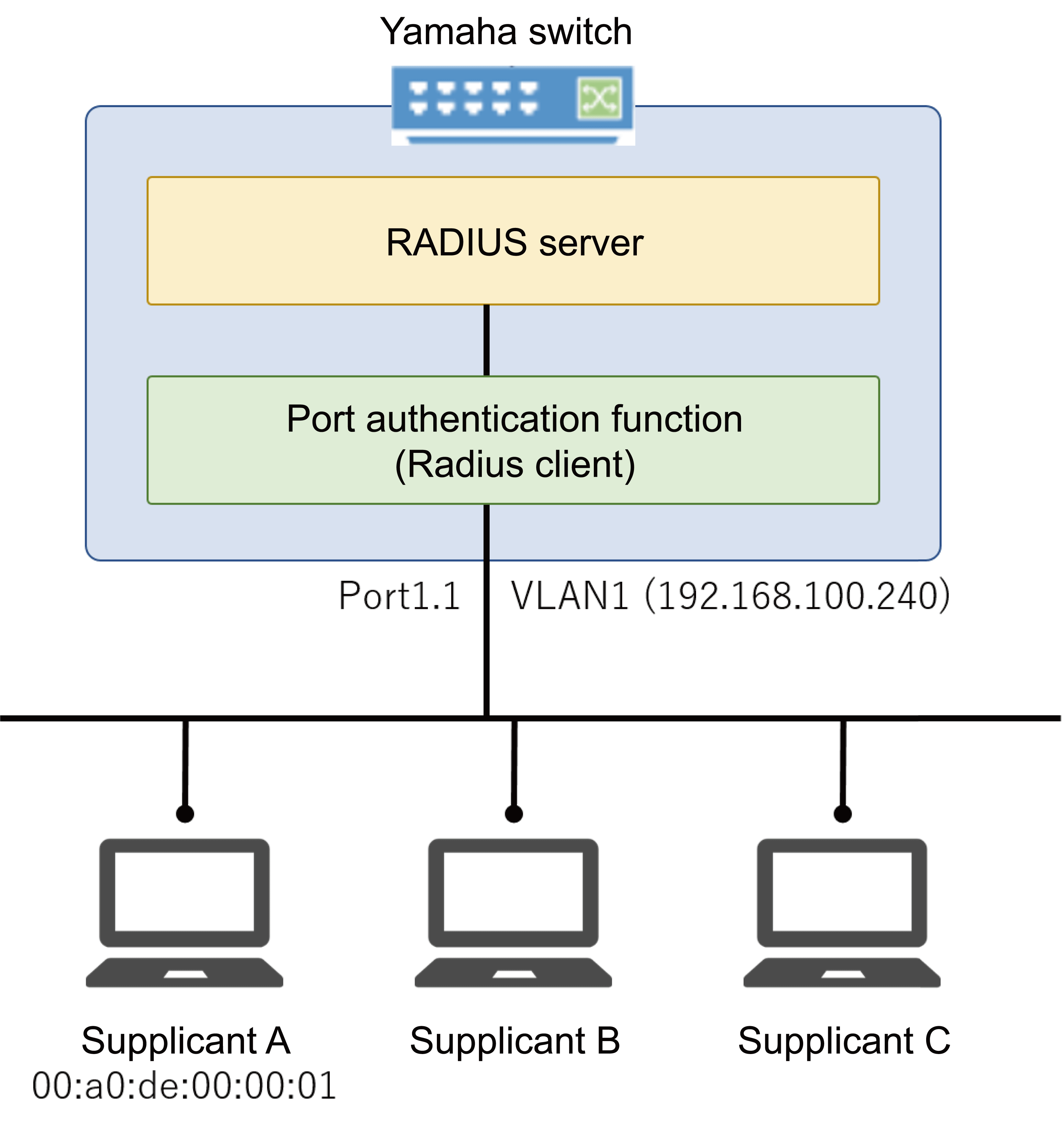
- Enable the local RADIUS server with the switch and register the user.
Yamaha# configure terminal Yamaha(config)# crypto pki generate ca Generate CA? (y/n): y Finished Yamaha(config)# radius-server local-profile Yamaha(config-radius)# user 00a0de000001 00a0de000001 auth peap Yamaha(config-radius)# user 8021xuser 8021xpass auth peap Yamaha(config-radius)# user webuser webpass auth peap Yamaha(config-radius)# exit Yamaha(config)# radius-server local enable Yamaha(config)# exit Yamaha# radius-server local refresh
- Assign an IP address to VLAN #1 for web authentication
Yamaha# configure terminal Yamaha(config)# interface vlan1 Yamaha(config-if)# ip-address 192.168.100.240/24
- Enable MAC authentication, IEEE802.1X authentication, and Web authentication on LAN port #1.
Yamaha# configure terminal Yamaha(config)# aaa authentication auth-mac Yamaha(config)# auth-mac auth-user unformatted lower-case Yamaha(config)# aaa authentication dot1x Yamaha(config)# aaa authentication auth-web Yamaha(config)# interface port1.1 Yamaha(config-if)# auth host-mode multi-supplicant Yamaha(config-if)# auth-mac enable Yamaha(config-if)# dot1x port-control auto Yamaha(config-if)# auth-web enable
- Set the RADIUS server used for the authentication function.
Yamaha# configure terminal Yamaha(config)# radius-server host 127.0.0.1 key secret_local
5-2 Using RADIUS server functionality for authentication of users logging in to a Yamaha router
If accessing a Yamaha router from a TELNET client, user login authentication and administrator privilege authentication is performed by the Yamaha switch RADIUS server.
That enables user login using the user ID “user1” and password “password1”.
Users can be promoted to administrator using the password “admin”.
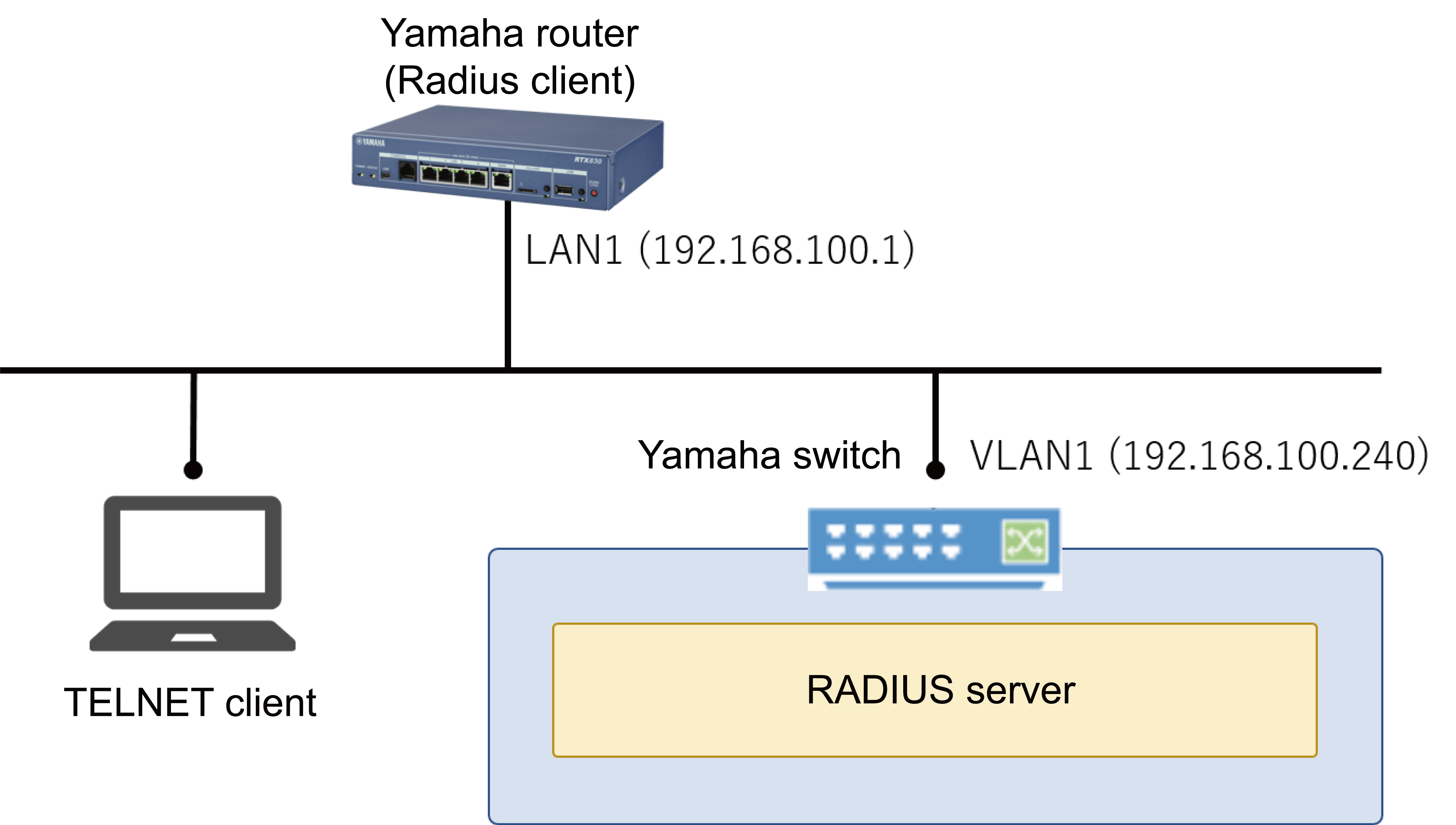
- Yamaha switch settings
- Specify the IP address in the interface.
Yamaha# configure terminal Yamaha(config)# interface vlan1 Yamaha(config-if)# ip address 192.168.100.240/24 Yamaha(config-if)# exit
- Generate a root Certificate Authority.
Yamaha(config)#crypto pki generate ca Generate CA? (y/n): y Finished
- Specify the RADIUS servers.
Yamaha(config)# radius-server local-profile Yamaha(config-radius)# nas 192.168.100.1 key yamaha Yamaha(config-radius)# user user1 password1 auth pap Yamaha(config-radius)# user *administrator admin auth pap Yamaha(config-radius)# exit
- Specify interfaces to which RADIUS clients can connect.
Yamaha(config)# radius-server local interface vlan1
- Enable RADIUS server functionality.
Yamaha(config)# radius-server local enable Yamaha(config)#exit
- Apply RADIUS server settings to actual operations.
Yamaha#radius-server local refresh Yamaha#
- Specify the IP address in the interface.
- Yamaha router settings
login radius use on administrator radius auth on ip lan1 address 192.168.100.1/24 radius auth on radius auth server 192.168.100.240 radius auth port 1812 radius secret yamaha
5-3 Using RADIUS server functionality for MAC authentication of Yamaha wireless access points (WLX series)
The Yamaha switch RADIUS server is used to authenticate the MAC address of supplicants connected to a Yamaha wireless access point.
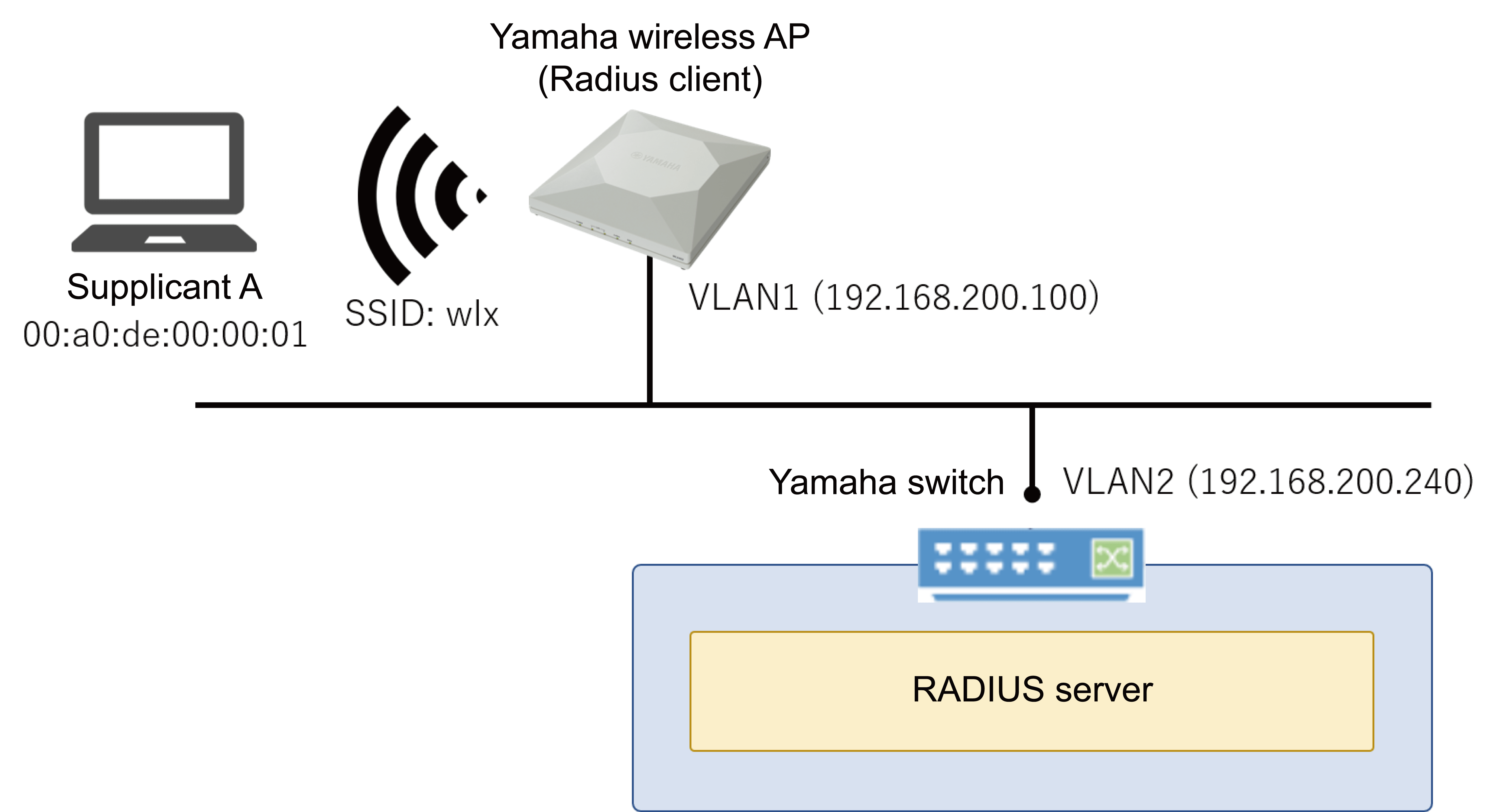
- Yamaha switch settings
- Specify the IP address in the interface.
Yamaha# configure terminal Yamaha(config)# interface vlan2 Yamaha(config-if)# ip address 192.168.200.240/24 Yamaha(config-if)# exit
- Generate a root Certificate Authority.
Yamaha(config)#crypto pki generate ca Generate CA? (y/n): y Finished
- Specify the RADIUS servers.
Yamaha(config)# radius-server local-profile Yamaha(config-radius)# nas 192.168.200.100 key yamaha Yamaha(config-radius)# user 00a0de000001 00a0de000001 auth pap ssid wlx Yamaha(config-radius)# exit
- Specify interfaces allowed to connect to RADIUS clients.
Yamaha(config)# radius-server local interface vlan2
- Enable RADIUS server functionality.
Yamaha(config)# radius-server local enable Yamaha(config)#exit
- Apply RADIUS server settings to actual operations.
Yamaha#radius-server local refresh Yamaha#
- Specify the IP address in the interface.
- Yamaha wireless AP (WLX402) settings
Note: Only for settings related to authentication. Configure other settings, such as for wireless functionality, separately according to the given environment.
ip vlan-id 1 address 192.168.200.100/24 airlink slect 1 airlink ssid wlx airlink radius auth on airlink radius server 192.168.200.240 airlink radius secret yamaha airlink enable 1
5-4 Using RADIUS server functionality to connect to a Yamaha wireless access point (WLX series) using a certificate
A supplicant with a certificate issued by the Yamaha switch installed is used to authenticate connections to a Yamaha wireless access point.
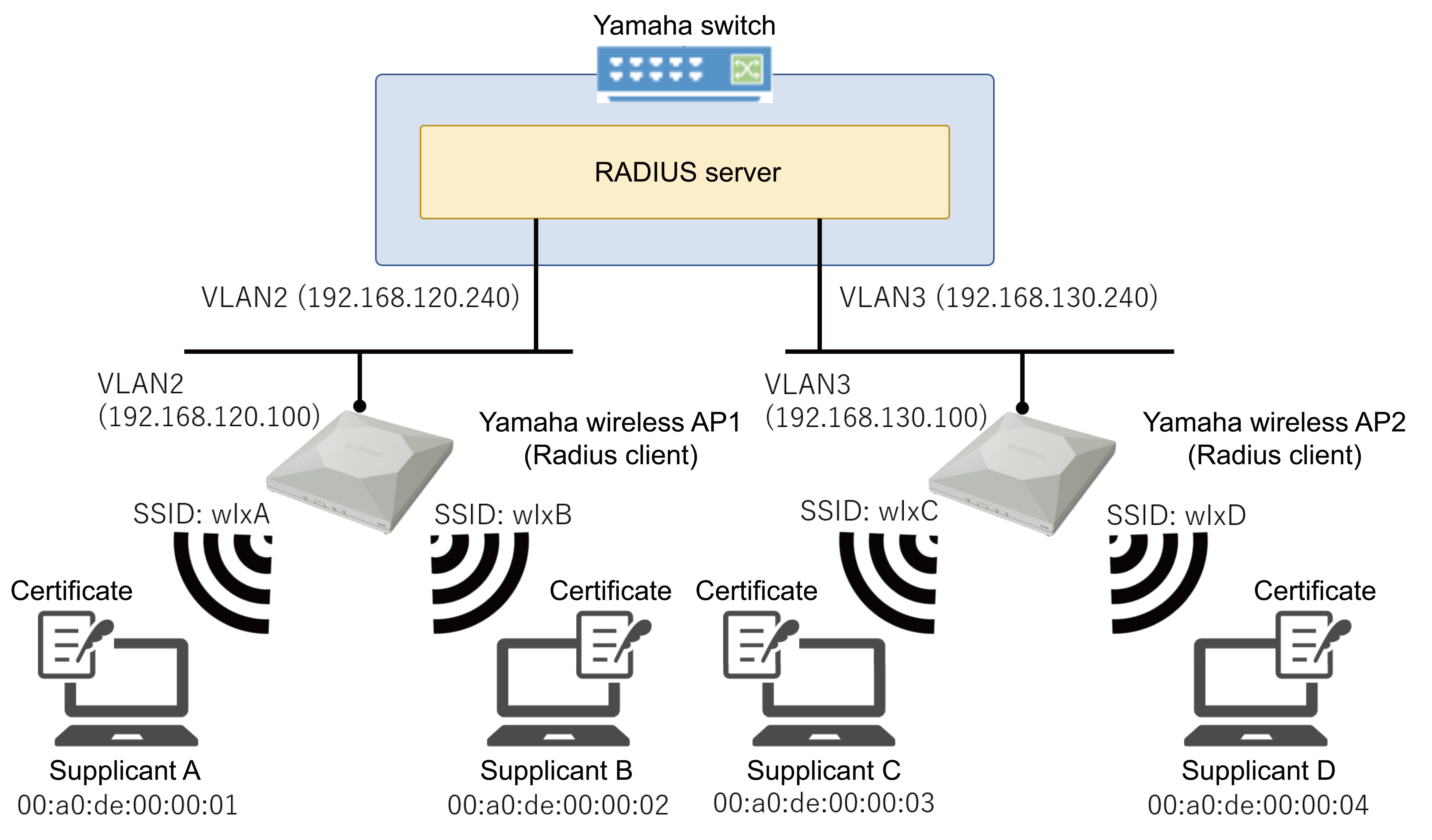
- Yamaha switch settings
- Specify the IP address in the interface.
Yamaha(config)# interface vlan2 Yamaha(config-if)# ip address 192.168.120.240/24 Yamaha(config-if)# exit
- Generate a root Certificate Authority.
Yamaha(config)#crypto pki generate ca Generate CA? (y/n): y Finished
- Specify the RADIUS servers.
Yamaha(config)# radius-server local-profile Yamaha(config-radius)# nas 192.168.120.100 key yamaha1 Yamaha(config-radius)# nas 192.168.130.100 key yamaha2 Yamaha(config-radius)# user user1 pass1 ssid wlxA Yamaha(config-radius)# user user2 pass2 ssid wlxB Yamaha(config-radius)# user user3 pass3 ssid wlxC Yamaha(config-radius)# user user4 pass4 ssid wlxD Yamaha(config-radius)# exit
- Specify interfaces allowed to connect to RADIUS clients.
Yamaha(config)# radius-server local interface vlan2 Yamaha(config)# radius-server local interface vlan3
- Enable RADIUS server functionality.
Yamaha(config)# radius-server local enable Yamaha(config)# exit
- Issue client certificates.
Install the issued certificates in supplicants A to D, respectively.
Yamaha# certificate user user1 Yamaha# certificate user user2 Yamaha# certificate user user3 Yamaha# certificate user user4
- Apply RADIUS server settings to actual operations.
Yamaha# radius-server local refresh
- Specify the IP address in the interface.
- Yamaha wireless AP1 (WLX402) settings
Note: Only for settings related to authentication. Configure other settings, such as for wireless functionality, separately according to the given environment.
ip vlan-id 2 address 192.168.120.100/24 airlink select 1 airlink ssid wlxA airlink vlan-id 2 airlink radius auth on airlink radius server 192.168.120.240 airlink radius secret yamaha1 airlink enable 1 airlink select 2 airlink ssid wlxB airlink vlan-id 2 airlink radius auth on airlink radius server 192.168.120.240 airlink radius secret yamaha1 airlink enable 2
- Yamaha wireless AP2 (WLX402) settings
Note: Only for settings related to authentication. Configure other settings, such as for wireless functionality, separately according to the given environment.
ip vlan-id 3 address 192.168.130.100/24 airlink select 1 airlink ssid wlxC airlink vlan-id 3 airlink radius auth on airlink radius server 192.168.130.240 airlink radius secret yamaha2 airlink enable 1 airlink select 2 airlink ssid wlxD airlink vlan-id 3 airlink radius auth on airlink radius server 192.168.130.240 airlink radius secret yamaha2 airlink enable 2
6 Points of Caution
- In the RADIUS server function, the time of the internal clock of this device is used for processing such as authentication processing and certificate issuance.
Therefore, it is necessary to always keep the internal clock of this device at the correct time. Time synchronization with NTP server is recommended.
- It is necessary to keep the root Certificate Authority consistent from its creation, so be careful not to delete it carelessly.
If it is deleted, the issued client certificates cannot be used, and client certificates must be reissued for all users.
Also, almost all settings related to the RADIUS server function will be deleted.
- Even if you create a root Certificate Authority with the same name on a Yamaha switch of the same model number, that root Certificate Authority will be a different one.
Client certificates can only be used with Yamaha switch authentication that has the root Certificate Authority used at the time of generation.
To maintain the same root Certificate Authority in multiple devices, see 3-13 Backing up and restoring all RADIUS server related information.
- A certificate cannot be issued for an IPv6 link local address even if the connection is from a RADIUS client.
- The characters permitted in user or other information by Yamaha switches is different than permitted by Yamaha wireless access points (WXL series). Those differences are indicated below.
(The characters in red are disallowed only by Yamaha switches)Item Yamaha switch restrictions Yamaha wireless access point restrictions Root certificate authority name
(CA-NAME option for crypto pki generate ca command)The following single-byte alphanumeric characters and symbols cannot be used
’\’ (backslash)
’/’
’[’
’]’
’?’
’ ‘ (space)
’"’ (double quote)The following single-byte alphanumeric characters and symbols cannot be used
’\’ (backslash)
’/’
’[’
’]’RADIUS client shared password
(SECRET parameter of nas command)The following single-byte alphanumeric characters and symbols cannot be used
’\’ (backslash)
’[’
’]’
’?’
’ ‘ (space)
’"’ (double quote)The following single-byte alphanumeric characters and symbols cannot be used
’\’ (backslash)
’[’
’]’User ID in user information
(USERID parameter of user command)
When the authentication method is EAP-TLSThe following single-byte alphanumeric characters and symbols cannot be used.
‘\’ (backslash)
’/’
’[’
’]’
’:’
’‘*’
’>’
’|’
’?’
’ ’ (space)
’"’ (double-quote)The following single-byte alphanumeric characters and symbols cannot be used
’\’ (backslash)
’/’
’[’
’]’User ID in user information
(USERID parameter of user command)
When the authentication method is PAP or PEAPThe following single-byte alphanumeric characters and symbols cannot be used.
‘\’ (backslash)
’[’
’]’
’?’
’ ’ (space)
’"’ (double quote)The following single-byte alphanumeric characters and symbols cannot be used
’\’ (backslash)
’[’
’]’Password in user information
(PASSWORD parameter of user command)The following single-byte alphanumeric characters and symbols cannot be used
’\’ (backslash)
’[’
’]’
’?’
’ ‘ (space)
’"’ (double quote)The following single-byte alphanumeric characters and symbols cannot be used
’\’ (backslash)
’[’
’]’Name in user information
(NAME option of user command)The following single-byte alphanumeric characters and symbols cannot be used.
’?’
’ ’ (space)
’"’ (double quote)All single-byte alphanumeric characters and symbols can be used.
7 Related Documentation
- Interface control functions: Port authentication functions
- SWX3220 Series Technical Data (Basic Functions)
- Other information
- SWX3220 Series Technical Data (Basic Functions)
- Other information
- SNMP MIB Reference
SNMP MIB Reference
1 SNMP MIB List
The SNMP MIBs that are supported by this product are shown below.
1.1 MIB tree
The MIB tree for MIB groups that are supported by this product are shown below.
iso(1)
|
+--std(0)
| |
| +--iso8802(8802)
| |
| +--ieee802dot1(1)
| |
| +--ieee802dot1mibs(1)
| |
| +--ieee8021paeMIB(1) (port authentication information)
| |
| +--lldpMIB(2)
| |
| +--lldpObjects(1) (LLDP information)
|
+--member-body(2)
| |
| +--us(840)
| |
| +--802dot3(10006)
| |
| +--snmpmibs(300)
| |
| +--lagMIB(43) (LACP link aggregation information)
|
+--org(3)
|
+--dod(6)
| |
| +--internet(1)
| |
| +--mgmt(2)
| | |
| | +--mib-2(1)
| | |
| | +--system(1) (system information)
| | |
| | +--interfaces(2) (interface information)
| | |
| | +--at(3) (mapping information for network addresses and physical addresses)
| | |
| | +--rmon(16) (RMON information)
| | |
| | +--dot1dBridge(17) (dot1dBridge information)
| | |
| | +--rip2(23) (RIP information)
| | |
| | +--ifMIB(31) (additional information for interface)
| | |
| | +--entityMIB(47) (entity information)
| | |
| | +--vrrpv3MIB(207) (VRRP information)
| |
| +--private(4)
| |
| +--enterprises(1)
| |
| +--yamaha(1182)
| |
| +--yamahaSW(3) (private MIB Yamaha switch information)
| |
| +--yamahaSWHardware(1) (hardware information)
| |
| +--yamahaSWFirmware(2) (firmware information)
| |
| +--yamahaSWL2ms(5) (L2MS information)
| |
| +--yamahaSWErrDisable(6) (error detection function information)
| |
| +--yamahaSWRmon(7) (RMON information)
| |
| +--yamahaSWTermMon(8) (terminal monitoring information)
| |
| +--yamahaSWBridge(9) (dot1dBridge information)
| |
| +--yamahaSWLoopDetect(11)(Loop detection information))
| |
| +--yamahaSWVrrp(12) (VRRP information)
|
+--ieee(111)
|
+--standards-association-numbers-series-standards(2)
|
+--lan-man-stds(802)
|
+--ieee802dot1(1)
|
+--ieee802dot1mibs(1)
|
+--lldpV2MIB(13) (LLDP information)
1.2 Standard MIB list
The standard MIB that are supported are shown below.
MIB groups and overview
| MIB group | Summary |
|---|---|
| ieee8021paeMIB group | Port authentication information |
| lldpMIB group | LLDP information |
| lagMIB group | LACP link aggregation information |
| system group | System information |
| interface group | Interface information |
| at group | Mapping information for physical addresses and network addresses |
| rmon group | RMON information |
| dot1dBridge group | dot1dBridge information |
| rip2 group | RIP information |
| ifMIB group | Additional information for interface |
| entityMIB group | entity information |
| vrrpv3MIB group | VRRP information |
1.3 Private MIB list
Private MIBs that are supported are shown below.
All of this information is related to Yamaha switches.
MIB groups and overview
| MIB group | Summary |
|---|---|
| yamahaSWHardware group | Hardware information |
| yamahaSWFirmware group | Firmware information |
| yamahaSWL2ms group | L2MS information |
| yamahaSWErrDisable group | Error detection function information |
| yamahaSWRmon group | RMON information |
| yamahaSWTermMon group | Terminal monitoring information |
| yamahaSWBridge group | dot1dBridge information |
| yamahaSWLoopDetect group | Loop detection information |
| yamahaSWVrrp group | VRRP information |
1.4 Standard MIB trap list
The standard MIB traps that are supported are shown below.
Traps and overview
| Trap | Summary |
|---|---|
| coldStart | Power OFF/ON notification |
| warmStart | Reload notification |
| linkDown | Linkdown notification |
| linkUp | Linkup notification |
| authenticationFailure | Notification of failed authentication |
| risingAlarm | Notification that RMON upper threshold value has been exceeded |
| fallingAlarm | Notification that RMON lower threshold value has been exceeded |
| newRoot | Notification that new root for bridge has been detected |
| topologyChange | Notification when a change in topology has been detected |
| vrrpv3NewMaster | Sends notification if master status changes |
| vrrpv3ProtoError | Sends notification if protocol error is detected |
1.5 Private MIB trap list
Private MIBs traps that are supported are shown below.
Traps and overview
| Trap | Summary |
|---|---|
| yshTemperatureStatusNormalTrap | Normal temperature status notification |
| yshTemperatureStatusWarningTrap | Warning temperature status notification |
| yshTemperatureStatusErrorTrap | Error temperature status notification |
| yshFanStoppedTrap | Fan stopped notification |
| yshFanSpeedUpTrap | Increased fan RPM notification |
| yshFanSpeedDownTrap | Decreased fan RPM notification |
| yshFanRecoveredTrap | Notification that stopped fan is restored |
| ysl2msFindAgent | Notification that L2MS agent was detected |
| ysl2msDetectDown | Notification that L2MS agent was lost |
| ysedTrap | Notification of detect/cancel for error detection function |
| ystmIfTermTrap | Notification of terminal monitoring (port) detection |
| ystmIpTermTrap | Notification of terminal monitoring (IP address) detection | ysldPortDetectLoopTrap | Loop detection notification |
| ysldPortResolveLoopTrap | Loop detection cancellation notification |
2 Definition of Terms Used
- MIB access classification
The MIB access used in subsequent explanations is described below.
MIB access classification
Access name Description R/O Access to the MIB is read-only R/W Access to the MIB is read-write R/NW Although the access to the MIB is read-write as per the standards, it is read-only on this product R/C Access to the MIB is read-create R/NC Although the access to the MIB is read-create as per the standards, it is read-only on this product N/A The MIB cannot be retrieved
Note: May be used as additional information for traps (variable-bindings)
3 Obtaining a private MIB
Private MIB files may be acquired from here.
4 Standard MIBs
Standard MIBs that are supported by this product are shown below.
4.1 ieee8021paeMIB group
This MIB is related to port authentication information.
The syntax defined in the ieee8021paeMIB group is shown below.
Syntax defined in the ieee8021paeMIB group
| Syntax | Definition |
|---|---|
| PaeControlledDirections | INTEGER ・both(0) ・in(1) |
| PaeControlledPortStatus | INTEGER ・authorized(1) ・unauthorized(2) |
| PaeControlledPortControl | INTEGER ・forceUnauthorized(1) ・auto(2) ・forceAuthorized(3) |
The ieee8021paeMIB group is divided into subgroups such as those shown below.
ieee8021paeMIB(1)
|
+--paeMIBObjects(1)
|
+--dot1xPaeSystem(1)
|
+--dot1xPaeAuthenticator(2)
dot1xPaeSystem group
| MIB name | OID | Access | Syntax | Description | ||
|---|---|---|---|---|---|---|
| dot1xPaeSystemAuthControl | 1.0.8802.1.1.1.1.1.1 | R/NW | INTEGER ・enabled(1) ・disabled(2) | Setting value for authentication function at the system level | ||
| dot1xPaePortTable | 1.0.8802.1.1.1.1.1.2 | N/A | System-level information table | |||
| dot1xPaePortEntry | 1.0.8802.1.1.1.1.1.2.1 | N/A | INDEX ・dot1xPaePortNumber | |||
| dot1xPaePortNumber | 1.0.8802.1.1.1.1.1.2.1.1 | N/A | InterfaceIndex | Port numbers for which the authentication function is enabled | ||
| dot1xPaePortProtocolVersion | 1.0.8802.1.1.1.1.1.2.1.2 | R/O | Unsigned32 | Protocol version (2, fixed) | ||
| dot1xPaePortCapabilities | 1.0.8802.1.1.1.1.1.2.1.3 | R/O | BITS | PAE functions supported by the port (0, fixed) | ||
| dot1xPaePortInitialize | 1.0.8802.1.1.1.1.1.2.1.4 | R/NW | TruthValue | Initialization control for ports (2, fixed) | ||
| dot1xPaePortReauthenticate | 1.0.8802.1.1.1.1.1.2.1.5 | R/NW | TruthValue | Re-authentication control for ports (2, fixed) | ||
dot1xPaeAuthenticator group
| MIB name | OID | Access | Syntax | Description | ||
|---|---|---|---|---|---|---|
| dot1xAuthConfigTable | 1.0.8802.1.1.1.1.2.1 | N/A | Structural object table for Authenticator PAE for each port | |||
| dot1xAuthConfigEntry | 1.0.8802.1.1.1.1.2.1.1 | N/A | INDEX ・dot1xPaePortNumber | |||
| dot1xAuthAdminControlledDirections | 1.0.8802.1.1.1.1.2.1.1.3 | R/NW | PaeControlledDirections | Packet forwarding operation in an unauthenticated state, controlled by management | ||
| dot1xAuthOperControlledDirections | 1.0.8802.1.1.1.1.2.1.1.4 | R/O | PaeControlledDirections | Packet forwarding operation in an unauthenticated state, controlled by operation | ||
| dot1xAuthAuthControlledPortStatus | 1.0.8802.1.1.1.1.2.1.1.5 | R/O | PaeControlledPortStatus | Port authentication status | ||
| dot1xAuthAuthControlledPortControl | 1.0.8802.1.1.1.1.2.1.1.6 | R/NW | PaeControlledPortControl | Setting value for 802.1X authentication operating mode | ||
| dot1xAuthQuietPeriod | 1.0.8802.1.1.1.1.2.1.1.7 | R/NW | Unsigned32 | Setting value for authentication restriction period | ||
| dot1xAuthSuppTimeout | 1.0.8802.1.1.1.1.2.1.1.9 | R/NW | Unsigned32 | Response wait time setting value for the supplicant | ||
| dot1xAuthServerTimeout | 1.0.8802.1.1.1.1.2.1.1.10 | R/NW | Unsigned32 | Setting value for server response wait time | ||
| dot1xAuthMaxReq | 1.0.8802.1.1.1.1.2.1.1.11 | R/NW | Unsigned32 | Setting value for number of times EAPOL packets are retransmitted | ||
| dot1xAuthReAuthPeriod | 1.0.8802.1.1.1.1.2.1.1.12 | R/NW | Unsigned32 | Setting value for reauthentication interval | ||
| dot1xAuthReAuthEnabled | 1.0.8802.1.1.1.1.2.1.1.13 | R/NW | TruthValue | Setting value for reauthentication function | ||
| dot1xAuthKeyTxEnabled | 1.0.8802.1.1.1.1.2.1.1.14 | R/NW | TruthValue | Constant value (2, fixed) used by Authenticator PAE state machine | ||
| dot1xAuthStatsTable | 1.0.8802.1.1.1.1.2.2 | N/A | Statistical data object table for Authenticator PAE associated with each port | |||
| dot1xAuthStatsEntry | 1.0.8802.1.1.1.1.2.2.1 | N/A | INDEX ・dot1xPaePortNumber | |||
| dot1xAuthEapolFramesRx | 1.0.8802.1.1.1.1.2.2.1.1 | R/O | Counter32 | No. of EAPOL frames that are received, all valid types | ||
| dot1xAuthEapolFramesTx | 1.0.8802.1.1.1.1.2.2.1.2 | R/O | Counter32 | No. of EAPOL frames that are transmitted, all types | ||
| dot1xAuthEapolStartFramesRx | 1.0.8802.1.1.1.1.2.2.1.3 | R/O | Counter32 | No. of EAPOL Start frames received | ||
| dot1xAuthEapolLogoffFramesRx | 1.0.8802.1.1.1.1.2.2.1.4 | R/O | Counter32 | No. of EAPOL Logoff frames received | ||
| dot1xAuthEapolRespIdFramesRx | 1.0.8802.1.1.1.1.2.2.1.5 | R/O | Counter32 | No. of EAP Response/Identity frames received | ||
| dot1xAuthEapolRespFramesRx | 1.0.8802.1.1.1.1.2.2.1.6 | R/O | Counter32 | No. of valid EAP Response frames, excepting EAP Response/Identity frames received | ||
| dot1xAuthEapolReqIdFramesTx | 1.0.8802.1.1.1.1.2.2.1.7 | R/O | Counter32 | No. of EAP Request/Identity frames transmitted | ||
| dot1xAuthEapolReqFramesTx | 1.0.8802.1.1.1.1.2.2.1.8 | R/O | Counter32 | No. of EAP Request frames, excepting EAP Request/Identity frames transmitted | ||
| dot1xAuthInvalidEapolFramesRx | 1.0.8802.1.1.1.1.2.2.1.9 | R/O | Counter32 | No. of frames within received EAPOL frames, for which frame type has not been approved | ||
| dot1xAuthEapLengthErrorFramesRx | 1.0.8802.1.1.1.1.2.2.1.10 | R/O | Counter32 | No. of received EAPOL frames, for which the packet body length is invalid | ||
| dot1xAuthLastEapolFrameVersion | 1.0.8802.1.1.1.1.2.2.1.11 | R/O | Unsigned32 | Protocol version numbers for most recently received EAPOL frames | ||
| dot1xAuthLastEapolFrameSource | 1.0.8802.1.1.1.1.2.2.1.12 | R/O | MacAddress | Source MAC address of EAPOL frames most recently received | ||
4.2 lldpMIB group
This MIB is related to LLDP information.
This product handles the following two MIB groups involved in the LLDP.
- lldpMIB group (MIB defined in IEEE Std 802.1AB-2005)
- lldpV2MIB group (MIB defined in IEEE Std 802.1AB-2009)
Though both MIBs handle the LLDP in the same way, both are supported to provide compatibility with other models.
Some MIBs refer to the same value.
The syntax defined for the lldpMIB group is shown below.Syntax defined in the lldpMIB group
| Syntax | Definition |
|---|---|
| LldpChassisIdSubtype | INTEGER ・chassisComponent(1) ・interfaceAlias(2) ・portComponent(3) ・macAddress(4) ・networkAddress(5) ・interfaceName(6) ・local(7) |
| LldpChassisId | OCTET STRING (SIZE (1..255)) |
| LldpPortIdSubtype | INTEGER ・interfaceAlias(1) ・portComponent(2) ・macAddress(3) ・networkAddress(4) ・interfaceName(5) ・agentCircuitId(6) ・local(7) |
| LldpPortId | OCTET STRING (SIZE (1..255)) |
| LldpSystemCapabilitiesMap | BITS ・other(0) ・repeater(1) ・bridge(2) ・wlanAccessPoint(3) ・router(4) ・telephone(5) ・docsisCableDevice(6) ・stationOnly(7) |
| LldpPortNumber | INTEGER32 (1..4096) |
| LldpXMedDeviceClass | INTEGER ・notDefined(0) ・endpointClass1(1) ・endpointClass2(2) ・endpointClass3(3) ・networkConnectivity(4) |
| LldpXMedCapabilities | INTEGER ・capabilities(0) ・networkPolicy(1) ・location(2) ・extendedPSE(3) ・extendedPD(4) ・inventory(5) |
| LldpManAddress | OCTET STRING (SIZE (1..31)) |
| LldpManAddrIfSubtype | INTEGER ・unknown(1) ・ifIndex(2) ・systemPortNumber(3) |
The lldpMIB group is divided into subgroups, such as shown below.
lldpObjects(1)
|
+--lldpConfiguration(1)
|
+--lldpStatistics(2)
|
+--lldpLocalSystemData(3)
|
+--lldpRemoteSystemsData(4)
|
+--lldpExtensions(5)
|
+--lldpXMedMIB(4795)
|
+--lldpXMedObjects(1)
|
+--lldpXMedConfig(1)
|
+--lldpXMedRemoteData(3)
lldpConfiguration group
| MIB name | OID | Access | Syntax | Description | ||
|---|---|---|---|---|---|---|
| lldpPortConfigTable | 1.0.8802.1.1.2.1.1.6 | N/A | Table of information for each port | |||
| lldpPortConfigEntry | 1.0.8802.1.1.2.1.1.6.1 | N/A | INDEX ・lldpPortConfigPortNum | |||
| lldpPortConfigAdminStatus | 1.0.8802.1.1.2.1.1.6.1.2 | R/NW | INTEGER ・txOnly(1) ・rxOnly(2) ・txAndRx(3) ・disabled(4) | LLDP transmission/reception status | ||
| lldpPortConfigNotificationEnable | 1.0.8802.1.1.2.1.1.6.1.3 | R/NW | TruthVal | LLDP notification status | ||
| lldpPortConfigTLVsTxEnable | 1.0.8802.1.1.2.1.1.6.1.4 | R/NW | BITS ・portDesc(0) ・sysName(1) ・sysDesc(2) ・sysCap(3) | Basic management TLV transmission item | ||
lldpStatistics group
| MIB name | OID | Access | Syntax | Description | ||
|---|---|---|---|---|---|---|
| lldpStatsRemTablesLastChangeTime | 1.0.8802.1.1.2.1.2.1 | R/O | TimeTicks | Time from system initialization until remote data update | ||
| lldpStatsRemTablesInserts | 1.0.8802.1.1.2.1.2.2 | R/O | INTEGER (0..4294967295) | Total number of entries added to the remote device management table | ||
| lldpStatsRemTablesDeletes | 1.0.8802.1.1.2.1.2.3 | R/O | INTEGER (0..4294967295) | Total number of entries deleted from the remote device management table | ||
| lldpStatsRemTablesDrops | 1.0.8802.1.1.2.1.2.4 | R/O | INTEGER (0..4294967295) | Total number of entries that could not be specified in the remote device management table | ||
| lldpStatsRemTablesAgeouts | 1.0.8802.1.1.2.1.2.5 | R/O | INTEGER (0..4294967295) | Total number of entries that exceeded the TTL time (aged out) and were deleted from the remote device management table | ||
| lldpStatsTxPortTable | 1.0.8802.1.1.2.1.2.6 | N/A | Table of information for each port | |||
| lldpStatsTxPortEntry | 1.0.8802.1.1.2.1.2.6.1 | N/A | INDEX ・lldpStatsTxPortNum | |||
| lldpStatsTxPortNum | 1.0.8802.1.1.2.1.2.6.1.1 | N/A | LldpPortNumber | |||
| lldpStatsTxPortFramesTotal | 1.0.8802.1.1.2.1.2.6.1.2 | R/O | INTEGER (0..4294967295) | Total number of LLDP frames transmitted | ||
| lldpStatsRxPortTable | 1.0.8802.1.1.2.1.2.7 | N/A | Table of information for each port | |||
| lldpStatsRxPortEntry | 1.0.8802.1.1.2.1.2.7.1 | N/A | INDEX ・lldpStatsRxPortNum | |||
| lldpStatsRxPortNum | 1.0.8802.1.1.2.1.2.7.1.1 | N/A | LldpPortNumber | |||
| lldpStatsRxPortFramesDiscardedTotal | 1.0.8802.1.1.2.1.2.7.1.2 | R/O | INTEGER (0..4294967295) | Number of LLDP frames discarded | ||
| lldpStatsRxPortFramesErrors | 1.0.8802.1.1.2.1.2.7.1.3 | R/O | INTEGER (0..4294967295) | Number of error frames received | ||
| lldpStatsRxPortFramesTotal | 1.0.8802.1.1.2.1.2.7.1.4 | R/O | INTEGER (0..4294967295) | Number of LLDP frames received | ||
| lldpStatsRxPortTLVsDiscardedTotal | 1.0.8802.1.1.2.1.2.7.1.5 | R/O | INTEGER (0..4294967295) | Number of TLVs discarded | ||
| lldpStatsRxPortTLVsUnrecognizedTotal | 1.0.8802.1.1.2.1.2.7.1.6 | R/O | INTEGER (0..4294967295) | Number of unrecognized TLVs received | ||
| lldpStatsRxPortAgeoutsTotal | 1.0.8802.1.1.2.1.2.7.1.7 | R/O | INTEGER (0..4294967295) | Number of entries that aged-out | ||
lldpLocalSystemData group
| MIB name | OID | Access | Syntax | Description | ||
|---|---|---|---|---|---|---|
| lldpLocChassisIdSubtype | 1.0.8802.1.1.2.1.3.1 | R/O | LldpChassisIdSubtype | Subtype of chassis ID | ||
| lldpLocChassisId | 1.0.8802.1.1.2.1.3.2 | R/O | LldpChassisId | Chassis ID | ||
| lldpLocSysName | 1.0.8802.1.1.2.1.3.3 | R/O | SnmpAdminString (SIZE (0..255)) | System name | ||
| lldpLocSysDesc | 1.0.8802.1.1.2.1.3.4 | R/O | SnmpAdminString (SIZE (0..255)) | System description | ||
| lldpLocSysCapSupported | 1.0.8802.1.1.2.1.3.5 | R/O | LldpSystemCapabilitiesMap | Functions supported by the system | ||
| lldpLocSysCapEnabled | 1.0.8802.1.1.2.1.3.6 | R/O | LldpSystemCapabilitiesMap | Functions enabled by the system | ||
| lldpLocPortTable | 1.0.8802.1.1.2.1.3.7 | N/A | Table of information for each port | |||
| lldpLocPortEntry | 1.0.8802.1.1.2.1.3.7.1 | N/A | INDEX ・lldpLocPortNum | |||
| lldpLocPortNum | 1.0.8802.1.1.2.1.3.7.1.1 | N/A | LldpPortNumber | |||
| lldpLocPortIdSubtype | 1.0.8802.1.1.2.1.3.7.1.2 | R/O | LldpPortIdSubtype | Subtype of port ID | ||
| lldpLocPortId | 1.0.8802.1.1.2.1.3.7.1.3 | R/O | OCTET STRING (SIZE (1..255)) | Port ID | ||
| lldpLocPortDesc | 1.0.8802.1.1.2.1.3.7.1.4 | R/O | SnmpAdminString (SIZE (0..255)) | Port description | ||
| lldpLocManAddrTable | 1.0.8802.1.1.2.1.3.8 | N/A | Table of local system management addresses | |||
| lldpLocManAddrEntry | 1.0.8802.1.1.2.1.3.8.1 | N/A | INDEX ・lldpV2LocManAddrSubtype ・lldpLocManAddr | |||
| lldpLocManAddrSubtype | 1.0.8802.1.1.2.1.3.8.1.1 | N/A | AddressFamilyNumbers | Sub-type for management address | ||
| lldpLocManAddr | 1.0.8802.1.1.2.1.3.8.1.2 | N/A | LldpManAddress | management address | ||
| lldpLocManAddrLen | 1.0.8802.1.1.2.1.3.8.1.3 | R/O | Integer32 | management address length | ||
| lldpLocManAddrIfSubtype | 1.0.8802.1.1.2.1.3.8.1.4 | R/O | LldpManAddrIfSubtype | Interface sub-type | ||
| lldpLocManAddrIfId | 1.0.8802.1.1.2.1.3.8.1.5 | R/O | Integer32 | Interface ID | ||
lldpRemoteSystemsData group
| MIB name | OID | Access | Syntax | Description | ||
|---|---|---|---|---|---|---|
| lldpRemTable | 1.0.8802.1.1.2.1.4.1 | N/A | Table of information for each port | |||
| lldpRemEntry | 1.0.8802.1.1.2.1.4.1.1 | N/A | INDEX ・lldpRemTimeMark ・lldpRemLocalPortNum ・lldpRemIndex | |||
| lldpRemTimeMark | 1.0.8802.1.1.2.1.4.1.1.1 | N/A | TimeFilter | |||
| lldpRemLocalPortNum | 1.0.8802.1.1.2.1.4.1.1.2 | N/A | LldpPortNumber | |||
| lldpRemIndex | 1.0.8802.1.1.2.1.4.1.1.3 | N/A | INTEGER32 (1..2147483647) | |||
| lldpRemChassisIdSubtype | 1.0.8802.1.1.2.1.4.1.1.4 | R/O | LldpChassisIdSubtype | Subtype of the remote device chassis ID | ||
| lldpRemChassisId | 1.0.8802.1.1.2.1.4.1.1.5 | R/O | SnmpAdminString (SIZE (0..255)) | Chassis ID of remote device | ||
| lldpRemPortIdSubtype | 1.0.8802.1.1.2.1.4.1.1.6 | R/O | LldpPortIdSubtype | Subtype of the remote device port ID | ||
| lldpRemPortId | 1.0.8802.1.1.2.1.4.1.1.7 | R/O | OCTET STRING (SIZE (1..255)) | Port ID of remote device | ||
| lldpRemPortDesc | 1.0.8802.1.1.2.1.4.1.1.8 | R/O | SnmpAdminString (SIZE (0..255)) | Description of remote device port | ||
| lldpRemSysName | 1.0.8802.1.1.2.1.4.1.1.9 | R/O | SnmpAdminString (SIZE (0..255)) | System name of remote device | ||
| lldpRemSysDesc | 1.0.8802.1.1.2.1.4.1.1.10 | R/O | SnmpAdminString (SIZE (0..255)) | System description of remote device | ||
| lldpRemSysCapSupported | 1.0.8802.1.1.2.1.4.1.1.11 | R/O | LldpSystemCapabilitiesMap | Functionality supported by the remote device system | ||
| lldpRemSysCapEnabled | 1.0.8802.1.1.2.1.4.1.1.12 | R/O | LldpSystemCapabilitiesMap | Functionality enabled in the remote device system | ||
| lldpRemManAddrTable | 1.0.8802.1.1.2.1.4.2 | N/A | ||||
| lldpRemManAddrEntry | 1.0.8802.1.1.2.1.4.2.1 | N/A | INDEX ・lldpRemTimeMark ・lldpRemLocalPortNum ・lldpRemIndex ・lldpRemManAddrSubtype ・lldpRemManAddr | |||
| lldpRemManAddrSubtype | 1.0.8802.1.1.2.1.4.2.1.1 | N/A | LldpPortNumber | |||
| lldpRemManAddr | 1.0.8802.1.1.2.1.4.2.1.2 | N/A | ||||
| lldpRemManAddrIfSubtype | 1.0.8802.1.1.2.1.4.2.1.3 | R/O | INTEGER ・unknown(1) ・ifIndex(2) ・systemPortNumber(3) | Subtype of remote device interface | ||
| lldpRemManAddrIfId | 1.0.8802.1.1.2.1.4.2.1.4 | R/O | Integer32 | Interface ID of remote device | ||
| lldpRemManAddrOID | 1.0.8802.1.1.2.1.4.2.1.5 | R/O | OBJECT IDENTIFIER | OID of the remote device management address | ||
| lldpRemUnknownTLVTable | 1.0.8802.1.1.2.1.4.3 | N/A | ||||
| lldpRemUnknownTLVEntry | 1.0.8802.1.1.2.1.4.3.1 | N/A | INDEX ・lldpRemTimeMark ・lldpRemLocalPortNum ・lldpRemIndex ・lldpRemUnknownTLVType | |||
| lldpRemUnknownTLVType | 1.0.8802.1.1.2.1.4.3.1.1 | N/A | LldpPortNumber | |||
| lldpRemUnknownTLVInfo | 1.0.8802.1.1.2.1.4.3.1.2 | R/O | LldpPortNumber | Latest undefined TLV information for remote device | ||
| lldpRemOrgDefInfoTable | 1.0.8802.1.1.2.1.4.4 | N/A | ||||
| lldpRemOrgDefInfoEntry | 1.0.8802.1.1.2.1.4.4.1 | N/A | INDEX ・lldpRemTimeMark ・lldpRemLocalPortNum ・lldpRemIndex ・lldpRemOrgDefInfoOUI ・lldpRemOrgDefInfoSubtype, lldpRemOrgDefInfoIndex | |||
| lldpRemOrgDefInfoOUI | 1.0.8802.1.1.2.1.4.4.1.1 | N/A | ||||
| lldpRemOrgDefInfoSubtype | 1.0.8802.1.1.2.1.4.3.1.2 | N/A | ||||
| lldpRemOrgDefInfoIndex | 1.0.8802.1.1.2.1.4.3.1.3 | N/A | ||||
| lldpRemOrgDefInfo | 1.0.8802.1.1.2.1.4.3.1.4 | R/O | OCTET STRING (SIZE (0..507)) | Index of undefined TLV information for remote device (Limited to IEEE802.1 and IEEE802.3) | ||
lldpXMedConfig group
| MIB name | OID | Access | Syntax | Description | ||
|---|---|---|---|---|---|---|
| lldpXMedLocDeviceClass | 1.0.8802.1.1.2.1.5.4795.1.1.1 | R/O | LldpXMedDeviceClass | Local device class | ||
| lldpXMedPortConfigTable | 1.0.8802.1.1.2.1.5.4795.1.1.2 | N/A | Table of information for each port | |||
| lldpXMedPortConfigEntry | 1.0.8802.1.1.2.1.5.4795.1.1.2.1 | N/A | INDEX - Port number | |||
| lldpXMedPortCapSupported | 1.0.8802.1.1.2.1.5.4795.1.1.2.1.1 | R/O | LldpXMedCapabilities | TLV transmission items supported by LLDP-MED | ||
| lldpXMedPortConfigTLVsTxEnable | 1.0.8802.1.1.2.1.5.4795.1.1.2.1.2 | R/NW | LldpXMedCapabilities | TLV items sent as LLDP-MED | ||
| lldpXMedPortConfigNotifEnable | 1.0.8802.1.1.2.1.5.4795.1.1.2.1.3 | R/NW | TruthValue | LLDP-MED notification status | ||
| lldpXMedFastStartRepeatCount | 1.0.8802.1.1.2.1.5.4795.1.1.3 | R/NW | Unsigned32 (1..10) | LLDP-MED fast transmission count | ||
lldpXMedRemoteData group
| MIB name | OID | Access | Syntax | Description | ||
|---|---|---|---|---|---|---|
| lldpXMedRemXPoETable | 1.0.8802.1.1.2.1.5.4795.1.3.5 | N/A | Remote device information table | |||
| lldpXMedRemXPoEEntry | 1.0.8802.1.1.2.1.5.4795.1.3.5.1 | N/A | INDEX ・lldpRemTimeMark ・lldpRemLocalPortNum ・lldpRemIndex | |||
| lldpXMedRemXPoEDeviceType | 1.0.8802.1.1.2.1.5.4795.1.3.5.1.1 | R/O | INTEGER ・unknown(1) ・pseDevice(2) ・pdDevice(3) ・none(4) | Indicates whether the remote device is PSE or PD | ||
| lldpXMedRemXPoEPSETable | 1.0.8802.1.1.2.1.5.4795.1.3.6 | N/A | PSE information table for remote device | |||
| lldpXMedRemXPoEPSEEntry | 1.0.8802.1.1.2.1.5.4795.1.3.6.1 | N/A | INDEX ・lldpRemTimeMark ・lldpRemLocalPortNum ・lldpRemIndex | |||
| lldpXMedRemXPoEPSEPowerAv | 1.0.8802.1.1.2.1.5.4795.1.3.6.1.1 | R/O | Integer(0..1023) | Power requirements of remote device (0.1 W increments) | ||
| lldpXMedRemXPoEPSEPowerSource | 1.0.8802.1.1.2.1.5.4795.1.3.6.1.2 | R/O | INTEGER ・unknown(1) ・fromPSE(2) ・local(3) ・localAndPSE(4) | Power supply type of remote device | ||
| lldpXMedRemXPoEPDPowerPriority | 1.0.8802.1.1.2.1.5.4795.1.3.6.1.3 | R/O | INTEGER ・unknown(1) ・critical(2) ・high(3) ・low(4) | Power supply priority of remote device | ||
| lldpXMedRemXPoEPDTable | 1.0.8802.1.1.2.1.5.4795.1.3.7 | N/A | PSE information table for remote device | |||
| lldpXMedRemXPoEPDEntry | 1.0.8802.1.1.2.1.5.4795.1.3.7.1 | N/A | INDEX ・lldpRemTimeMark ・lldpRemLocalPortNum ・lldpRemIndex | |||
| lldpXMedRemXPoEPDPowerReq | 1.0.8802.1.1.2.1.5.4795.1.3.7.1.1 | R/O | Integer(0..1023) | Power requirements of remote device (0.1 W increments) | ||
| lldpXMedRemXPoEPDPowerSource | 1.0.8802.1.1.2.1.5.4795.1.3.7.1.2 | R/O | INTEGER ・unknown(1) ・fromPSE(2) ・local(3) ・localAndPSE(4) | Power supply type of remote device | ||
| lldpXMedRemXPoEPDPowerPriority | 1.0.8802.1.1.2.1.5.4795.1.3.7.1.3 | R/O | INTEGER ・unknown(1) ・critical(2) ・high(3) ・low(4) | Power supply priority of remote device | ||
The lldpV2MIB group is divided into subgroups such as those shown below.
lldpV2MIB(13)
|
+--lldpV2Objects(1)
|
+--lldpV2Configuration(1)
|
+--lldpV2Statistics(2)
|
+--lldpV2LocalSystemData(3)
|
+--lldpV2RemoteSystemsData(4)lldpV2Configuration group
| MIB name | OID | Access | Syntax | Description | ||
|---|---|---|---|---|---|---|
| lldpV2PortConfigTable | 1.3.111.2.802.1.1.13.1.1.8 | N/A | Table for managing transmitted information for each port | |||
| lldpV2PortConfigEntry | 1.3.111.2.802.1.1.13.1.1.8.1 | N/A | INDEX ・lldpV2PortConfigIfIndex ・lldpV2PortConfigDestAddressIndex | |||
| lldpV2PortConfigIfIndex | 1.3.111.2.802.1.1.13.1.1.8.1.1 | N/A | InterfaceIndex | Index for each port | ||
| lldpV2PortConfigDestAddressIndex | 1.3.111.2.802.1.1.13.1.1.8.1.2 | N/A | LldpV2DestAddressTableIndex | Source MAC address index | ||
| lldpV2PortConfigAdminStatus | 1.3.111.2.802.1.1.13.1.1.8.1.3 | R/O | INTEGER ・txOnly(1) ・rxOnly(2) ・txAndRx(3) ・disabled(4) | LLDP transmission/reception status | ||
| lldpV2PortConfigNotificationEnable | 1.3.111.2.802.1.1.13.1.1.8.1.4 | R/O | TruthValue | LLDP notification status | ||
| lldpV2PortConfigTLVsTxEnable | 1.3.111.2.802.1.1.13.1.1.8.1.5 | R/O | BITS ・portDesc(0) ・sysName(1) ・sysDesc(2) ・sysCap(3) | Basic management TLV transmission item | ||
| lldpV2DestAddressTable | 1.3.111.2.802.1.1.13.1.1.9 | N/A | Table of MAC addresses used by LLDP | |||
| lldpV2DestAddressTableEntry | 1.3.111.2.802.1.1.13.1.1.9.1 | N/A | INDEX ・lldpV2AddressTableIndex | |||
| lldpV2AddressTableIndex | 1.3.111.2.802.1.1.13.1.1.9.1.1 | N/A | LldpV2DestAddressTableIndex | Source MAC address index | ||
| lldpV2DestMacAddress | 1.3.111.2.802.1.1.13.1.1.9.1.2 | R/O | MacAddress | MAC address used for LLDP transmission | ||
lldpV2Statistics group
| MIB name | OID | Access | Syntax | Description | ||
|---|---|---|---|---|---|---|
| lldpV2StatsRemTablesLastChangeTime | 1.3.111.2.802.1.1.13.1.2.1 | R/O | TimeStamp | Time from system initialization until remote data update | ||
| lldpV2StatsRemTablesInserts | 1.3.111.2.802.1.1.13.1.2.2 | R/O | ZeroBasedCounter32 | Total number of entries added to device management table | ||
| lldpV2StatsRemTablesDeletes | 1.3.111.2.802.1.1.13.1.2.3 | R/O | ZeroBasedCounter32 | Total number of entries deleted from device management table | ||
| lldpV2StatsRemTablesDrops | 1.3.111.2.802.1.1.13.1.2.4 | R/O | ZeroBasedCounter32 | Total number of entries that could not be set to device management table | ||
| lldpV2StatsRemTablesAgeouts | 1.3.111.2.802.1.1.13.1.2.5 | R/O | ZeroBasedCounter32 | Total number of entries that exceeded TTL time (aged out) and were deleted from device management table | ||
| lldpV2StatsTxPortTable | 1.3.111.2.802.1.1.13.1.2.6 | N/A | Table of statistical information for LLDP transmission | |||
| lldpV2StatsTxPortEntry | 1.3.111.2.802.1.1.13.1.2.6.1 | N/A | INDEX ・lldpV2StatsTxIfInde ・lldpV2StatsTxDestMACAddress | |||
| lldpV2StatsTxIfIndex | 1.3.111.2.802.1.1.13.1.2.6.1.1 | N/A | InterfaceIndex | Port index | ||
| lldpV2StatsTxDestMACAddress | 1.3.111.2.802.1.1.13.1.2.6.1.2 | N/A | LldpV2DestAddressTableIndex | Source MAC address index | ||
| lldpV2StatsTxPortFramesTotal | 1.3.111.2.802.1.1.13.1.2.6.1.3 | R/O | Counter32 | Total number of LLDP frames transmitted | ||
| lldpV2StatsTxLLDPDULengthErrors | 1.3.111.2.802.1.1.13.1.2.6.1.4 | R/O | Counter32 | Total no. of LLDP frame length errors | ||
| lldpV2StatsRxPortTable | 1.3.111.2.802.1.1.13.1.2.7 | N/A | Table of statistical information for LLDP reception | |||
| lldpV2StatsRxPortEntry | 1.3.111.2.802.1.1.13.1.2.7.1 | N/A | INDEX ・lldpV2StatsRxDestIfIndex ・lldpV2StatsRxDestMACAddress | |||
| lldpV2StatsRxDestIfIndex | 1.3.111.2.802.1.1.13.1.2.7.1.1 | N/A | InterfaceIndex | Port index | ||
| lldpV2StatsRxDestMACAddress | 1.3.111.2.802.1.1.13.1.2.7.1.2 | N/A | LldpV2DestAddressTableIndex | Source MAC address index | ||
| lldpV2StatsRxPortFramesDiscardedTotal | 1.3.111.2.802.1.1.13.1.2.7.1.3 | R/O | Counter32 | Number of LLDP frames discarded | ||
| lldpV2StatsRxPortFramesErrors | 1.3.111.2.802.1.1.13.1.2.7.1.4 | R/O | Counter32 | Number of error frames received | ||
| lldpV2StatsRxPortFramesTotal | 1.3.111.2.802.1.1.13.1.2.7.1.5 | R/O | Counter32 | No. of LLDP frames received | ||
| lldpV2StatsRxPortTLVsDiscardedTotal | 1.3.111.2.802.1.1.13.1.2.7.1.6 | R/O | Counter32 | Number of LLDP frames discarded | ||
| lldpV2StatsRxPortTLVsUnrecognizedTotal | 1.3.111.2.802.1.1.13.1.2.7.1.7 | R/O | Counter32 | Number of unrecognized TLVs received | ||
| lldpV2StatsRxPortAgeoutsTotal | 1.3.111.2.802.1.1.13.1.2.7.1.8 | R/O | ZeroBasedCounter32 | Number of entries that aged-out | ||
lldpV2LocalSystemData group
| MIB name | OID | Access | Syntax | Description | ||
|---|---|---|---|---|---|---|
| lldpV2LocChassisIdSubtype | 1.3.111.2.802.1.1.13.1.3.1 | R/O | LldpV2ChassisIdSubtype | Subtype of chassis ID | ||
| lldpV2LocChassisId | 1.3.111.2.802.1.1.13.1.3.2 | R/O | LldpV2ChassisId | Chassis ID | ||
| lldpV2LocSysName | 1.3.111.2.802.1.1.13.1.3.3 | R/O | SnmpAdminString (SIZE (0..255)) | System name | ||
| lldpV2LocSysDesc | 1.3.111.2.802.1.1.13.1.3.4 | R/O | SnmpAdminString (SIZE (0..255)) | System description | ||
| lldpV2LocSysCapSupported | 1.3.111.2.802.1.1.13.1.3.5 | R/O | LldpV2SystemCapabilitiesMap | Functions supported by the system | ||
| lldpV2LocSysCapEnabled | 1.3.111.2.802.1.1.13.1.3.6 | R/O | LldpV2SystemCapabilitiesMap | Functions enabled by the system | ||
| lldpV2LocPortTable | 1.3.111.2.802.1.1.13.1.3.7 | N/A | Table of local port information | |||
| lldpV2LocPortEntry | 1.3.111.2.802.1.1.13.1.3.7.1 | N/A | INDEX ・lldpV2LocPortIfIndex | |||
| lldpV2LocPortIfIndex | 1.3.111.2.802.1.1.13.1.3.7.1.1 | N/A | InterfaceIndex | Port index | ||
| lldpV2LocPortIdSubtype | 1.3.111.2.802.1.1.13.1.3.7.1.2 | R/O | LldpV2PortIdSubtype | Subtype of port ID | ||
| lldpV2LocPortId | 1.3.111.2.802.1.1.13.1.3.7.1.3 | R/O | LldpV2PortId | Port ID | ||
| lldpV2LocPortDesc | 1.3.111.2.802.1.1.13.1.3.7.1.4 | R/O | SnmpAdminString (SIZE (0..255)) | Port description | ||
| lldpV2LocManAddrTable | 1.3.111.2.802.1.1.13.1.3.8 | N/A | Table of local system management addresses | |||
| lldpV2LocManAddrEntry | 1.3.111.2.802.1.1.13.1.3.8.1 | N/A | INDEX ・lldpV2LocManAddrSubtype ・lldpV2LocManAddr | |||
| lldpV2LocManAddrSubtype | 1.3.111.2.802.1.1.13.1.3.8.1.1 | N/A | AddressFamilyNumbers | Sub-type for management address | ||
| lldpV2LocManAddr | 1.3.111.2.802.1.1.13.1.3.8.1.2 | N/A | LldpV2ManAddress | management address | ||
| lldpV2LocManAddrLen | 1.3.111.2.802.1.1.13.1.3.8.1.3 | R/O | Unsigned32 | management address length | ||
| lldpV2LocManAddrIfSubtype | 1.3.111.2.802.1.1.13.1.3.8.1.4 | R/O | LldpV2ManAddrIfSubtype | Interface sub-type | ||
| lldpV2LocManAddrIfId | 1.3.111.2.802.1.1.13.1.3.8.1.5 | R/O | Unsigned32 | Interface ID | ||
lldpV2RemoteSystemsData group
| MIB name | OID | Access | Syntax | Description | ||
|---|---|---|---|---|---|---|
| lldpV2RemTable | 1.3.111.2.802.1.1.13.1.4.1 | N/A | Table of information for connected remote devices | |||
| lldpV2RemEntry | 1.3.111.2.802.1.1.13.1.4.1.1 | N/A | INDEX ・lldpV2RemTimeMark ・lldpV2RemLocalIfIndex ・lldpV2RemLocalDestMACAddress ・lldpV2RemIndex | |||
| lldpV2RemTimeMark | 1.3.111.2.802.1.1.13.1.4.1.1.1 | N/A | TimeFilter | Time filter for lldpV2RemEntry | ||
| lldpV2RemLocalIfIndex | 1.3.111.2.802.1.1.13.1.4.1.1.2 | N/A | InterfaceIndex | Port index | ||
| lldpV2RemLocalDestMACAddress | 1.3.111.2.802.1.1.13.1.4.1.1.3 | N/A | LldpV2DestAddressTableIndex | Destination MAC address | ||
| lldpV2RemIndex | 1.3.111.2.802.1.1.13.1.4.1.1.4 | N/A | Unsigned32(1..2147483647) | Remote system index | ||
| lldpV2RemChassisIdSubtype | 1.3.111.2.802.1.1.13.1.4.1.1.5 | R/O | LldpV2ChassisIdSubtype | Subtype of chassis ID | ||
| lldpV2RemChassisId | 1.3.111.2.802.1.1.13.1.4.1.1.6 | R/O | LldpV2ChassisId | Chassis ID | ||
| lldpV2RemPortIdSubtype | 1.3.111.2.802.1.1.13.1.4.1.1.7 | R/O | LldpV2PortIdSubtype | Subtype of port ID | ||
| lldpV2RemPortId | 1.3.111.2.802.1.1.13.1.4.1.1.8 | R/O | LldpV2PortId | Port ID | ||
| lldpV2RemPortDesc | 1.3.111.2.802.1.1.13.1.4.1.1.9 | R/O | SnmpAdminString (SIZE (0..255)) | Port description | ||
| lldpV2RemSysName | 1.3.111.2.802.1.1.13.1.4.1.1.10 | R/O | SnmpAdminString (SIZE (0..255)) | System name | ||
| lldpV2RemSysDesc | 1.3.111.2.802.1.1.13.1.4.1.1.11 | R/O | SnmpAdminString (SIZE (0..255)) | System description | ||
| lldpV2RemSysCapSupported | 1.3.111.2.802.1.1.13.1.4.1.1.12 | R/O | LldpV2SystemCapabilitiesMap | Functions supported by the system | ||
| lldpV2RemSysCapEnabled | 1.3.111.2.802.1.1.13.1.4.1.1.13 | R/O | LldpV2SystemCapabilitiesMap | Functions enabled on the system | ||
| lldpV2RemRemoteChanges | 1.3.111.2.802.1.1.13.1.4.1.1.14 | R/O | TruthValue | Flag indicating that a change in the MIB occurred on the remote device | ||
| lldpV2RemTooManyNeighbors | 1.3.111.2.802.1.1.13.1.4.1.1.15 | R/O | TruthValue | Flag indicating that the number of connected remote devices exceeded the limit of the management table | ||
| lldpV2RemManAddrTable | 1.3.111.2.802.1.1.13.1.4.2 | N/A | Table of remote system management addresses | |||
| lldpV2RemManAddrEntry | 1.3.111.2.802.1.1.13.1.4.2.1 | N/A | INDEX ・lldpV2RemTimeMark ・lldpV2RemLocalIfIndex ・lldpV2RemLocalDestMACAddress ・lldpV2RemIndex ・lldpV2RemManAddrSubtype ・lldpV2RemManAddr | |||
| lldpV2RemManAddrSubtype | 1.3.111.2.802.1.1.13.1.4.2.1.1 | N/A | AddressFamilyNumbers | Sub-type for management address | ||
| lldpV2RemManAddr | 1.3.111.2.802.1.1.13.1.4.2.1.2 | N/A | LldpV2ManAddress | Remote system management addresses | ||
| lldpV2RemManAddrIfSubtype | 1.3.111.2.802.1.1.13.1.4.2.1.3 | R/O | LldpV2ManAddrIfSubtype | Interface sub-type | ||
| lldpV2RemManAddrIfId | 1.3.111.2.802.1.1.13.1.4.2.1.4 | R/O | Unsigned32 | Interface ID | ||
| lldpV2RemManAddrOID | 1.3.111.2.802.1.1.13.1.4.2.1.5 | R/O | OBJECT IDENTIFIER | OID of management interface | ||
| lldpV2RemUnknownTLVTable | 1.3.111.2.802.1.1.13.1.4.3 | N/A | Table of undefined TLV information | |||
| lldpV2RemUnknownTLVEntry | 1.3.111.2.802.1.1.13.1.4.3.1 | N/A | INDEX ・lldpV2RemTimeMark ・lldpV2RemLocalIfIndex ・lldpV2RemLocalDestMACAddress ・lldpV2RemIndex ・lldpV2RemUnknownTLVType | |||
| lldpV2RemUnknownTLVType | 1.3.111.2.802.1.1.13.1.4.3.1.1 | N/A | Unsigned32(9..126) | Undefined TLV types | ||
| lldpV2RemUnknownTLVInfo | 1.3.111.2.802.1.1.13.1.4.3.1.2 | R/O | OCTET STRING (SIZE (0..511)) | Information for undefined TLVs | ||
| lldpV2RemOrgDefInfoTable | 1.3.111.2.802.1.1.13.1.4.4 | N/A | Table for OUI information | |||
| lldpV2RemOrgDefInfoEntry | 1.3.111.2.802.1.1.13.1.4.4.1 | N/A | INDEX ・lldpV2RemTimeMark ・lldpV2RemLocalIfIndex ・lldpV2RemLocalDestMACAddress ・lldpV2RemIndex ・lldpV2RemOrgDefInfoOUI ・lldpV2RemOrgDefInfoSubtype ・lldpV2RemOrgDefInfoIndex | |||
| lldpV2RemOrgDefInfoOUI | 1.3.111.2.802.1.1.13.1.4.4.1.1 | N/A | OCTET STRING (SIZE (3)) | OUI information for remote system | ||
| lldpV2RemOrgDefInfoSubtype | 1.3.111.2.802.1.1.13.1.4.4.1.2 | N/A | Unsigned32(1..255) | OUI information sub-type for remote system | ||
| lldpV2RemOrgDefInfoIndex | 1.3.111.2.802.1.1.13.1.4.4.1.3 | N/A | Unsigned32(1..2147483647) | Index for OUI information and OUI information sub-types | ||
| lldpV2RemOrgDefInfo | 1.3.111.2.802.1.1.13.1.4.4.1.4 | R/O | OCTET STRING (SIZE (0..507)) | Information defined for each organization | ||
4.3 lagMIB group
This MIB is related to LACP link aggregation information.
The syntax defined in the lagMIB group is shown below.
Syntax defined in the lagMIB group
| Syntax | Definition |
|---|---|
| LacpKey | INTEGER (1..127) Note: Although this is INTEGER (0..65535) as per the standards, on this product it is in the range of INTEGER (1..127) |
| LacpState | BITS ・lacpActivity(0) ・lacpTimeout(1) ・aggregation(2) ・synchronization(3) ・collecting(4) ・distributing(5) ・defaulted(6) ・expired(7) |
| ChurnState | INTEGER ・noChurn(1) ・churn(2) ・churnMonitor(3) |
The lagMIB group is divided into subgroups such as those shown below.
lagMIB(43)
|
+--lagMIBObjects(1)
|
+--dot3adAgg(1)
|
+--dot3adAggPort(2)
|
+--dot3adTablesLastChanged(3)
dot3adAgg group
| MIB name | OID | Access | Syntax | Description | ||
|---|---|---|---|---|---|---|
| dot3adAggTable | 1.2.840.10006.300.43.1.1.1 | N/A | LACP information table for system | |||
| dot3adAggEntry | 1.2.840.10006.300.43.1.1.1.1 | N/A | INDEX ・dot3adAggIndex | |||
| dot3adAggIndex | 1.2.840.10006.300.43.1.1.1.1.1 | N/A | InterfaceIndex | LACP logical interface number | ||
| dot3adAggMACAddress | 1.2.840.10006.300.43.1.1.1.1.2 | R/O | MacAddress | MAC address for LACP logical interface | ||
| dot3adAggActorSystemPriority | 1.2.840.10006.300.43.1.1.1.1.3 | R/NW | INTEGER (1..65535) Note: Although this is INTEGER (0..65535) as per the standards, on this product it is in the range of INTEGER (1..65535) Same applies to other priority-related lagMIB | LACP system priority for this device | ||
| dot3adAggActorSystemID | 1.2.840.10006.300.43.1.1.1.1.4 | R/NW | MacAddress | LACP system ID for the device itself | ||
| dot3adAggAggregateOrIndividual | 1.2.840.10006.300.43.1.1.1.1.5 | R/O | TruthValue | Whether operating as Aggregate (true) or as individual links (alternate waiting ports) (false) | ||
| dot3adAggActorAdminKey | 1.2.840.10006.300.43.1.1.1.1.6 | R/NW | LacpKey | ADMIN Key (identifier ID for the LACP logical interface) used in managing this device “Used in managing” means the setting values for ADMIN properties or the config value. Same applies to other lagMIB | ||
| dot3adAggActorOperKey | 1.2.840.10006.300.43.1.1.1.1.7 | R/O | LacpKey | ADMIN Key (identifier ID for the LACP logical interface) used in operation, for this device “Used in operating” means the current values of the current operation, which are exchanged by the LACP protocol. Same applies to other lagMIB | ||
| dot3adAggPartnerSystemID | 1.2.840.10006.300.43.1.1.1.1.8 | R/O | MacAddress | LACP system ID of the opposing device | ||
| dot3adAggPartnerSystemPriority | 1.2.840.10006.300.43.1.1.1.1.9 | R/O | INTEGER (1..65535) | LACP system priority for the opposing device | ||
| dot3adAggPartnerOperKey | 1.2.840.10006.300.43.1.1.1.1.10 | R/O | LacpKey | ADMIN Key (identifier ID for the LACP logical interface) used in operation, for the opposing device | ||
| dot3adAggCollectorMaxDelay | 1.2.840.10006.300.43.1.1.1.1.11 | R/NW | INTEGER (0..65535) | Delay time from when the LACP packet is received to the time it is reflected in operation | ||
| dot3adAggPortListTable | 1.2.840.10006.300.43.1.1.2 | N/A | LACP port list table for the system | |||
| dot3adAggPortListEntry | 1.2.840.10006.300.43.1.1.2.1 | N/A | INDEX ・dot3adAggIndex | |||
| dot3adAggPortListPorts | 1.2.840.10006.300.43.1.1.2.1.1 | R/O | PortList | List of ports where LACP is used. Bits are assigned in the following order, starting with the most significant bit shown on interface (port) bitmap. Ports 1.1 to 1.51, port 1.52, ports 2.1 to 2.51, and port 2.52 If port 1.4 and port 2.4 are used, for example, then the following values are indicated in hexadecimal. 10 00 00 00 00 00 01 00 00 00 00 00 00 | ||
dot3adAggPort group
| MIB name | OID | Access | Syntax | Description | ||
|---|---|---|---|---|---|---|
| dot3adAggPortTable | 1.2.840.10006.300.43.1.2.1 | N/A | Table of information for ports used by the LACP | |||
| dot3adAggPortEntry | 1.2.840.10006.300.43.1.2.1.1 | N/A | INDEX ・dot3adAggPortIndex | |||
| dot3adAggPortIndex | 1.2.840.10006.300.43.1.2.1.1.1 | N/A | InterfaceIndex | Port interface number | ||
| dot3adAggPortActorSystemPriority | 1.2.840.10006.300.43.1.2.1.1.2 | R/NW | INTEGER (1..65535) | LACP system priority for this device | ||
| dot3adAggPortActorSystemID | 1.2.840.10006.300.43.1.2.1.1.3 | R/O | MacAddress | LACP system ID for the device itself | ||
| dot3adAggPortActorAdminKey | 1.2.840.10006.300.43.1.2.1.1.4 | R/NW | LacpKey | ADMIN Key (identifier ID for the LACP logical interface) used in managing this device | ||
| dot3adAggPortActorOperKey | 1.2.840.10006.300.43.1.2.1.1.5 | R/NW | LacpKey | ADMIN Key (identifier ID for the LACP logical interface) used in operation, for this device | ||
| dot3adAggPortPartnerAdminSystemPriority | 1.2.840.10006.300.43.1.2.1.1.6 | R/NW | INTEGER (1..65535) | LACP system priority used in management, for the opposing device | ||
| dot3adAggPortPartnerOperSystemPriority | 1.2.840.10006.300.43.1.2.1.1.7 | R/O | INTEGER (1..65535) | LACP system priority used in operation, for the opposing device | ||
| dot3adAggPortPartnerAdminSystemID | 1.2.840.10006.300.43.1.2.1.1.8 | R/NW | MacAddress | LACP system ID used in management, for the opposing device | ||
| dot3adAggPortPartnerOperSystemID | 1.2.840.10006.300.43.1.2.1.1.9 | R/O | MacAddress | LACP system ID used in operation, for the opposing device | ||
| dot3adAggPortPartnerAdminKey | 1.2.840.10006.300.43.1.2.1.1.10 | R/NW | LacpKey | ADMIN Key (identifier ID for the LACP logical interface) used in management, for the opposing device | ||
| dot3adAggPortPartnerOperKey | 1.2.840.10006.300.43.1.2.1.1.11 | R/O | LacpKey | ADMIN Key (identifier ID for the LACP logical interface) used in operation, for the opposing device | ||
| dot3adAggPortSelectedAggID | 1.2.840.10006.300.43.1.2.1.1.12 | R/O | InterfaceIndex | Logical interface number selected by the port | ||
| dot3adAggPortAttachedAggID | 1.2.840.10006.300.43.1.2.1.1.13 | R/O | InterfaceIndex | Logical interface number connected to the port | ||
| dot3adAggPortActorPort | 1.2.840.10006.300.43.1.2.1.1.14 | R/O | INTEGER (0..65535) | Physical interface number of this device | ||
| dot3adAggPortActorPortPriority | 1.2.840.10006.300.43.1.2.1.1.15 | R/NW | INTEGER (0..65535) | Port priority for physical interface of this device | ||
| dot3adAggPortPartnerAdminPort | 1.2.840.10006.300.43.1.2.1.1.16 | R/NW | INTEGER (0..65535) | Physical interface number used in management, for the opposing device | ||
| dot3adAggPortPartnerOperPort | 1.2.840.10006.300.43.1.2.1.1.17 | R/O | INTEGER (0..65535) | Physical interface number used in operation, for the opposing device | ||
| dot3adAggPortPartnerAdminPortPriority | 1.2.840.10006.300.43.1.2.1.1.18 | R/NW | INTEGER (1..65535) | Port priority of physical interface used in management, for the opposing device | ||
| dot3adAggPortPartnerOperPortPriority | 1.2.840.10006.300.43.1.2.1.1.19 | R/O | INTEGER (1..65535) | Port priority for physical interface used in operation, for the opposing device | ||
| dot3adAggPortActorAdminState | 1.2.840.10006.300.43.1.2.1.1.20 | R/NW | LacpState | Actor_State used in management, for this device ActorState is a status variable that shows internal transitions | ||
| dot3adAggPortActorOperState | 1.2.840.10006.300.43.1.2.1.1.21 | R/O | LacpState | Actor_State used in operation, for this device | ||
| dot3adAggPortPartnerAdminState | 1.2.840.10006.300.43.1.2.1.1.22 | R/NW | LacpState | Actor_State used in management, for the opposing device | ||
| dot3adAggPortPartnerOperState | 1.2.840.10006.300.43.1.2.1.1.23 | R/O | LacpState | Actor_State used in operation, for the opposing device | ||
| dot3adAggPortAggregateOrIndividual | 1.2.840.10006.300.43.1.2.1.1.24 | R/O | TruthValue | Whether Aggregate (true), or individual physical interfaces (alternate waiting ports) (false) | ||
| dot3adAggPortStatsTable | 1.2.840.10006.300.43.1.2.2 | N/A | Table of statistical information for ports used by the LACP | |||
| dot3adAggPortStatsEntry | 1.2.840.10006.300.43.1.2.2.1 | N/A | INDEX ・dot3adAggPortIndex | |||
| dot3adAggPortStatsLACPDUsRx | 1.2.840.10006.300.43.1.2.2.1.1 | R/O | Counter32 | No. of correct LACPDU received by the physical interface | ||
| dot3adAggPortStatsMarkerPDUsRx | 1.2.840.10006.300.43.1.2.2.1.2 | R/O | Counter32 | No. of correct marker frames received by the physical interface | ||
| dot3adAggPortStatsMarkerResponsePDUsRx | 1.2.840.10006.300.43.1.2.2.1.3 | R/O | Counter32 | No. of correct marker response frames received by the physical interface | ||
| dot3adAggPortStatsUnknownRx | 1.2.840.10006.300.43.1.2.2.1.4 | R/O | Counter32 | No. of unknown frames received by the physical interface | ||
| dot3adAggPortStatsIllegalRx | 1.2.840.10006.300.43.1.2.2.1.5 | R/O | Counter32 | No. of frames received by the physical interface on which the EtherType was 0x8809 but the PDU was invalid | ||
| dot3adAggPortStatsLACPDUsTx | 1.2.840.10006.300.43.1.2.2.1.6 | R/O | Counter32 | No. of LACPDU transmitted from physical interface | ||
| dot3adAggPortStatsMarkerPDUsTx | 1.2.840.10006.300.43.1.2.2.1.7 | R/O | Counter32 | No. of marker frames transmitted from physical interface | ||
| dot3adAggPortStatsMarkerResponsePDUsTx | 1.2.840.10006.300.43.1.2.2.1.8 | R/O | Counter32 | No. of marker response frames transmitted from physical interface | ||
| dot3adAggPortDebugTable | 1.2.840.10006.300.43.1.2.3 | N/A | Debug information table for ports used by the LACP | |||
| dot3adAggPortDebugEntry | 1.2.840.10006.300.43.1.2.3.1 | N/A | INDEX ・dot3adAggPortIndex | |||
| dot3adAggPortDebugRxState | 1.2.840.10006.300.43.1.2.3.1.1 | R/O | INTEGER ・current(1) ・expired(2) ・defaulted(3) ・initialize(4) ・lacpDisabled(5) ・portDisabled(6) | Status of LACP protocol “Receive machine” transition variable | ||
| dot3adAggPortDebugLastRxTime | 1.2.840.10006.300.43.1.2.3.1.2 | R/O | TimeTicks | Internal time when logical interface last received data | ||
| dot3adAggPortDebugMuxState | 1.2.840.10006.300.43.1.2.3.1.3 | R/O | INTEGER ・detached(1) ・waiting(2) ・attached(3) ・collecting(4) ・distributing(5) ・collecting_distributing(6) | Status of LACP protocol “Mux machine” transition variable | ||
| dot3adAggPortDebugMuxReason | 1.2.840.10006.300.43.1.2.3.1.4 | R/O | DisplayString | Reason why most recent LACP protocol “Mux machine” transition variable was changed | ||
| dot3adAggPortDebugActorChurnState | 1.2.840.10006.300.43.1.2.3.1.5 | R/O | ChurnState | Status of “Churn Detection” transition variable for LACP protocol of this device | ||
| dot3adAggPortDebugPartnerChurnState | 1.2.840.10006.300.43.1.2.3.1.6 | R/O | ChurnState | Status of LACP protocol “Churn Detection” transition variable for the opposing device | ||
| dot3adAggPortDebugActorChurnCount | 1.2.840.10006.300.43.1.2.3.1.7 | R/O | Counter32 | No. of times that the LACP protocol “Churn Detection” status variable changed to ACTOR_CHURN status | ||
| dot3adAggPortDebugPartnerChurnCount | 1.2.840.10006.300.43.1.2.3.1.8 | R/O | Counter32 | No. of times that LACP protocol “Churn Detection” status variable changed to PARTNER_CHURN status | ||
| dot3adAggPortDebugActorSyncTransitionCount | 1.2.840.10006.300.43.1.2.3.1.9 | R/O | Counter32 | No. of times that LACP protocol “Mux machine” status variable of this device changed to IN_SYNC status | ||
| dot3adAggPortDebugPartnerSyncTransitionCount | 1.2.840.10006.300.43.1.2.3.1.10 | R/O | Counter32 | No. of times that the LACP protocol “Mux machine” status variable of the opposing device changed to IN_SYNC status | ||
| dot3adAggPortDebugActorChangeCount | 1.2.840.10006.300.43.1.2.3.1.11 | R/O | Counter32 | No. of times that the LAG ID of this device was changed | ||
| dot3adAggPortDebugPartnerChangeCount | 1.2.840.10006.300.43.1.2.3.1.12 | R/O | Counter32 | No. of times that the LAG ID of the opposing device was changed | ||
dot3adTablesLastChanged group
| MIB name | OID | Access | Syntax | Description |
|---|---|---|---|---|
| dot3adTablesLastChanged | 1.2.840.10006.300.43.1.3 | R/O | TimeTicks | Most recent time in which Dot3adAggTable, dot3adAggPortListTable, and dot3adAggPortTable was changed Note: This is always “0” on this product |
4.4 system group
This MIB is related to system information.
system group
| MIB name | OID | Access | Syntax | Description |
|---|---|---|---|---|
| sysDescr | 1.3.6.1.2.1.1.1 | R/O | DisplayString (SIZE (0..255)) | The description of the device. Device name and firmware revision |
| sysObjectID | 1.3.6.1.2.1.1.2 | R/O | OBJECT IDENTIFIER | Device OID that is defined by Yamaha’s private MIB |
| sysUpTimeInstance | 1.3.6.1.2.1.1.3 | R/O | TimeTicks | Elapsed time from boot |
| sysContact | 1.3.6.1.2.1.1.4 | R/W | DisplayString (SIZE (0..255)) | Administrator contact information Setting value for snmp-server contact command |
| sysName | 1.3.6.1.2.1.1.5 | R/W | DisplayString (SIZE (0..255)) | Administrative name Setting value for hostname command |
| sysLocation | 1.3.6.1.2.1.1.6 | R/W | DisplayString (SIZE (0..255)) | Device location Setting value for snmp-server location command |
| sysServices | 1.3.6.1.2.1.1.7 | R/O | INTEGER (0..127) | Value that indicates services the device supports |
4.5 interface group
This MIB is related to interface information.
interface group
| MIB name | OID | Access | Syntax | Description | ||
|---|---|---|---|---|---|---|
| ifNumber | 1.3.6.1.2.1.2.1 | R/O | Integer32 | No. of interfaces | ||
| ifTable | 1.3.6.1.2.1.2.2 | N/A | Interface information table | |||
| ifEntry | 1.3.6.1.2.1.2.2.1 | N/A | INDEX ・ifIndex | |||
| ifIndex | 1.3.6.1.2.1.2.2.1.1 | R/O | InterfaceIndex | Interface ID number | ||
| ifDescr | 1.3.6.1.2.1.2.2.1.2 | R/O | DisplayString (SIZE (0..255)) | Description of the interface. Interface name | ||
| ifType | 1.3.6.1.2.1.2.2.1.3 | R/O | IANAifType ・ethernetCsmacd(6) ・l3ipvlan(136), others | Types of interfaces | ||
| ifMtu | 1.3.6.1.2.1.2.2.1.4 | R/O | Integer32 | Maximum frame size that can be transmitted/received | ||
| ifSpeed | 1.3.6.1.2.1.2.2.1.5 | R/O | Gauge32 | Interface speed | ||
| ifPhysAddress | 1.3.6.1.2.1.2.2.1.6 | R/O | PhysAddress | MAC address | ||
| ifAdminStatus | 1.3.6.1.2.1.2.2.1.7 | R/W | INTEGER ・up(1) ・down(2) | Desirable interface status | ||
| ifOperStatus | 1.3.6.1.2.1.2.2.1.8 | R/O | INTEGER ・up(1) ・down(2) | Current status of interface | ||
| ifLastChange | 1.3.6.1.2.1.2.2.1.9 | R/O | TimeTicks | Time when the interface changed to the current status (time elapsed time from boot) | ||
| ifInOctets | 1.3.6.1.2.1.2.2.1.10 | R/O | Counter32 | Total no. of octets received | ||
| ifInUcastPkts | 1.3.6.1.2.1.2.2.1.11 | R/O | Counter32 | No. of unicast packets notified to higher protocol | ||
| ifInNUcastPkts | 1.3.6.1.2.1.2.2.1.12 | R/O | Counter32 | Number of non-unicast packets notified to higher protocol | ||
| ifInDiscards | 1.3.6.1.2.1.2.2.1.13 | R/O | Counter32 | No. of packets that were discarded, despite no errors detected | ||
| ifInErrors | 1.3.6.1.2.1.2.2.1.14 | R/O | Counter32 | No. of packets not notified to higher protocol due to errors | ||
| ifInUnknownProtos | 1.3.6.1.2.1.2.2.1.15 | R/O | Counter32 | No. of discarded packets, due to an unsupported protocol | ||
| ifOutOctets | 1.3.6.1.2.1.2.2.1.16 | R/O | Counter32 | Total no. of octets transmitted | ||
| ifOutUcastPkts | 1.3.6.1.2.1.2.2.1.17 | R/O | Counter32 | No. of unicast packets requested for transmission by a higher protocol | ||
| ifOutNUcastPkts | 1.3.6.1.2.1.2.2.1.18 | R/O | Counter32 | No. of non-unicast packets requested for transmission by a higher protocol | ||
| ifOutDiscards | 1.3.6.1.2.1.2.2.1.19 | R/O | Counter32 | No. of packets that were discarded for transmission, despite no errors detected | ||
| ifOutErrors | 1.3.6.1.2.1.2.2.1.20 | R/O | Counter32 | No. of packets not transmitted due to errors | ||
| ifSpecific | 1.3.6.1.2.1.2.2.1.22 | R/O | OBJECT IDENTIFIER | Reference to MIB that defines interface media characteristics If no reference exists, this will be 0.0 | ||
4.6 at group
This MIB is related to mapping information for physical addresses and network addresses.
at group
| MIB name | OID | Access | Syntax | Description | ||
|---|---|---|---|---|---|---|
| atTable | 1.3.6.1.2.1.3.1 | N/A | Table of mapping information for physical addresses and network addresses | |||
| atEntry | 1.3.6.1.2.1.3.1.1 | N/A | INDEX ・atIfIndex ・atNetAddress | |||
| atIfIndex | 1.3.6.1.2.1.3.1.1.1 | R/NW | INTEGER | ifIndex for the corresponding interface | ||
| atPhysAddress | 1.3.6.1.2.1.3.1.1.2 | R/NW | PhysAddress | Physical address | ||
| atNetAddress | 1.3.6.1.2.1.3.1.1.3 | R/NW | NetworkAddress | IP address corresponding to the physical address | ||
4.7 rmon group
This MIB is related to RMON information.
The syntax defined in the rmon group is shown below.
Syntax defined in the rmon group
| Syntax | Definition |
|---|---|
| OwnerString | OCTET STRING (SIZE (0..127)) |
| EntryStatus | INTEGER ・valid(1) ・createRequest(2) ・underCreation(3) ・invalid(4) |
The rmon group is divided into subgroups such as those shown below.
rmon(16)
|
+--statistics(1)
|
+--history(2)
|
+--alarm(3)
|
+--event(9)
statistics group
| MIB name | OID | Access | Syntax | Description | ||
|---|---|---|---|---|---|---|
| etherStatsTable | 1.3.6.1.2.1.16.1.1 | N/A | Table of statistical information for Ethernet | |||
| etherStatsEntry | 1.3.6.1.2.1.16.1.1.1 | N/A | INDEX ・etherStatsIndex | |||
| etherStatsIndex | 1.3.6.1.2.1.16.1.1.1.1 | R/O | Integer32 (1..65535) | Index of entries | ||
| etherStatsDataSource | 1.3.6.1.2.1.16.1.1.1.2 | R/C | OBJECT IDENTIFIER | Interface being monitored | ||
| etherStatsDropEvents | 1.3.6.1.2.1.16.1.1.1.3 | R/O | Counter32 | Number of packets dropped | ||
| etherStatsOctets | 1.3.6.1.2.1.16.1.1.1.4 | R/O | Counter32 | Number of octets received | ||
| etherStatsPkts | 1.3.6.1.2.1.16.1.1.1.5 | R/O | Counter32 | Number of packets received | ||
| etherStatsBroadcastPkts | 1.3.6.1.2.1.16.1.1.1.6 | R/O | Counter32 | Number of broadcast packets received | ||
| etherStatsMulticastPkts | 1.3.6.1.2.1.16.1.1.1.7 | R/O | Counter32 | Number of multicast packets received | ||
| etherStatsCRCAlignErrors | 1.3.6.1.2.1.16.1.1.1.8 | R/O | Counter32 | Number of FCS error packets received | ||
| etherStatsUndersizePkts | 1.3.6.1.2.1.16.1.1.1.9 | R/O | Counter32 | Number of undersize packets received (packets smaller than 64 octets) | ||
| etherStatsOversizePkts | 1.3.6.1.2.1.16.1.1.1.10 | R/O | Counter32 | Number of oversize packets received (packets larger than 1518 octets) | ||
| etherStatsFragments | 1.3.6.1.2.1.16.1.1.1.11 | R/O | Counter32 | Number of fragment packets received (packets smaller than 64 octets with abnormal FCS) | ||
| etherStatsJabbers | 1.3.6.1.2.1.16.1.1.1.12 | R/O | Counter32 | Number of jabber packets received (packets larger than 1518 octets with abnormal FCS) | ||
| etherStatsCollisions | 1.3.6.1.2.1.16.1.1.1.13 | R/O | Counter32 | Number of collisions | ||
| etherStatsOwner | 1.3.6.1.2.1.16.1.1.1.20 | R/C | OwnerString | Name of owner | ||
| etherStatsStatus | 1.3.6.1.2.1.16.1.1.1.21 | R/C | EntryStatus | Status of statistical group | ||
history group
| MIB name | OID | Access | Syntax | Description | ||
|---|---|---|---|---|---|---|
| historyControlTable | 1.3.6.1.2.1.16.2.1 | N/A | Table of control information for the history group | |||
| historyControlEntry | 1.3.6.1.2.1.16.2.1.1 | N/A | INDEX ・historyControlIndex | |||
| historyControlIndex | 1.3.6.1.2.1.16.2.1.1.1 | R/O | Integer32 (1..65535) | Index of entries | ||
| historyControlDataSource | 1.3.6.1.2.1.16.2.1.1.2 | R/C | OBJECT IDENTIFIER | Interface being monitored | ||
| historyControlBucketsRequested | 1.3.6.1.2.1.16.2.1.1.3 | R/C | Integer32 (1..65535) | Number of history group history saves requested | ||
| historyControlBucketsGranted | 1.3.6.1.2.1.16.2.1.1.4 | R/O | Integer32 (1..65535) | Number of history group histories saved | ||
| historyControlInterval | 1.3.6.1.2.1.16.2.1.1.5 | R/C | Integer32 (1..3600) | Interval at which history group histories are saved | ||
| historyControlOwner | 1.3.6.1.2.1.16.2.1.1.6 | R/C | OwnerString | Name of owner | ||
| historyControlStatus | 1.3.6.1.2.1.16.2.1.1.7 | R/C | EntryStatus | History group status | ||
| etherHistoryTable | 1.3.6.1.2.1.16.2.2 | N/A | Table of history information | |||
| etherHistoryEntry | 1.3.6.1.2.1.16.2.2.1 | N/A | INDEX ・etherHistoryIndex ・etherHistorySampleIndex | |||
| etherHistoryIndex | 1.3.6.1.2.1.16.2.2.1.1 | R/O | Integer32 (1..65535) | Same value as the index value of historyControlIndex | ||
| etherHistorySampleIndex | 1.3.6.1.2.1.16.2.2.1.2 | R/O | Integer32 (1..2147483647) | Index of history entries | ||
| etherHistoryIntervalStart | 1.3.6.1.2.1.16.2.2.1.3 | R/O | TimeTicks | Interval at which history group histories are saved | ||
| etherHistoryDropEvents | 1.3.6.1.2.1.16.2.2.1.4 | R/O | Counter32 | Number of packets dropped | ||
| etherHistoryOctets | 1.3.6.1.2.1.16.2.2.1.5 | R/O | Counter32 | Number of octets received | ||
| etherHistoryPkts | 1.3.6.1.2.1.16.2.2.1.6 | R/O | Counter32 | Number of packets received | ||
| etherHistoryBroadcastPkts | 1.3.6.1.2.1.16.2.2.1.7 | R/O | Counter32 | Number of broadcast packets received | ||
| etherHistoryMulticastPkts | 1.3.6.1.2.1.16.2.2.1.8 | R/O | Counter32 | Number of multicast packets received | ||
| etherHistoryCRCAlignErrors | 1.3.6.1.2.1.16.2.2.1.9 | R/O | Counter32 | Number of FCS error packets received | ||
| etherHistoryUndersizePkts | 1.3.6.1.2.1.16.2.2.1.10 | R/O | Counter32 | Number of undersize packets received (packets smaller than 64 octets) | ||
| etherHistoryOversizePkts | 1.3.6.1.2.1.16.2.2.1.11 | R/O | Counter32 | Number of oversize packets received (packets larger than 1518 octets) | ||
| etherHistoryFragments | 1.3.6.1.2.1.16.2.2.1.12 | R/O | Counter32 | Number of fragment packets received (packets smaller than 64 octets with abnormal FCS) | ||
| etherHistoryJabbers | 1.3.6.1.2.1.16.2.2.1.13 | R/O | Counter32 | Number of jabber packets received (packets larger than 1518 octets with abnormal FCS) | ||
| etherHistoryCollisions | 1.3.6.1.2.1.16.2.2.1.14 | R/O | Counter32 | Number of collisions | ||
| etherHistoryUtilization | 1.3.6.1.2.1.16.2.2.1.15 | R/O | Integer32 (0..10000) | Estimated value of network usage ratio | ||
alarm group
| MIB name | OID | Access | Syntax | Description | ||
|---|---|---|---|---|---|---|
| alarmTable | 1.3.6.1.2.1.16.3.1 | N/A | Table of information for the alarm group | |||
| alarmEntry | 1.3.6.1.2.1.16.3.1.1 | N/A | INDEX ・alarmIndex | |||
| alarmIndex | 1.3.6.1.2.1.16.3.1.1.1 | R/O | Integer32 (1..65535) | Index of entries | ||
| alarmInterval | 1.3.6.1.2.1.16.3.1.1.2 | R/C | Integer32 | Sampling interval | ||
| alarmVariable | 1.3.6.1.2.1.16.3.1.1.3 | R/C | OBJECT IDENTIFIER | MIB object to be monitored | ||
| alarmSampleType | 1.3.6.1.2.1.16.3.1.1.4 | R/C | INTEGER ・absoluteValue(1) ・deltaValue(2) | Sampling type | ||
| alarmValue | 1.3.6.1.2.1.16.3.1.1.5 | R/O | Integer32 | Estimated value | ||
| alarmStartupAlarm | 1.3.6.1.2.1.16.3.1.1.6 | R/C | INTEGER ・risingAlarm(1) ・fallingAlarm(2) ・risingOrFallingAlarm(3) | Threshold value used for first alarm determination | ||
| alarmRisingThreshold | 1.3.6.1.2.1.16.3.1.1.7 | R/C | Integer32 | Upper threshold value | ||
| alarmFallingThreshold | 1.3.6.1.2.1.16.3.1.1.8 | R/C | Integer32 | Lower threshold value | ||
| alarmRisingEventIndex | 1.3.6.1.2.1.16.3.1.1.9 | R/C | Integer32 (0..65535) | Event index when crossing upper limit | ||
| alarmFallingEventIndex | 1.3.6.1.2.1.16.3.1.1.10 | R/C | Integer32 (0..65535) | Event index when crossing lower limit | ||
| alarmOwner | 1.3.6.1.2.1.16.3.1.1.11 | R/C | OwnerString | Name of owner | ||
| alarmStatus | 1.3.6.1.2.1.16.3.1.1.12 | R/C | EntryStatus | Alarm group status | ||
event group
| MIB name | OID | Access | Syntax | Description | ||
|---|---|---|---|---|---|---|
| eventTable | 1.3.6.1.2.1.16.9.1 | N/A | Table of information for event group | |||
| eventEntry | 1.3.6.1.2.1.16.9.1.1 | N/A | INDEX ・eventIndex | |||
| eventIndex | 1.3.6.1.2.1.16.9.1.1.1 | R/O | Integer32 (1..65535) | Index of entries | ||
| eventDescription | 1.3.6.1.2.1.16.9.1.1.2 | R/C | DisplayString (SIZE (0..127)) | Event description | ||
| eventType | 1.3.6.1.2.1.16.9.1.1.3 | R/C | INTEGER ・none(1) ・log(2) ・snmptrap(3) ・logandtrap(4) | Event type | ||
| eventCommunity | 1.3.6.1.2.1.16.9.1.1.4 | R/C | OCTET STRING (SIZE (0..127)) | Community name | ||
| eventLastTimeSent | 1.3.6.1.2.1.16.9.1.1.5 | R/O | TimeTicks | Event execution time | ||
| eventOwner | 1.3.6.1.2.1.16.9.1.1.6 | R/C | OwnerString | Name of owner | ||
| eventStatus | 1.3.6.1.2.1.16.9.1.1.7 | R/C | EntryStatus | Event group status | ||
4.8 dot1dBridge group
This MIB is related to dot1dBridge information.
The syntax defined in the dot1dBridge group is shown below.
Syntax defined in the dot1dBridge group
| Syntax | Definition |
|---|---|
| BridgeId | OCTET STRING (SIZE (8)) |
| Timeout | Integer32 |
| PortList | OCTET STRING |
| VlanIndex | Unsigned32 |
| VlanId | Integer32 (1..4094) |
The dot1dBridge group is divided into subgroups such as those shown below.
dot1dBridge(17)
|
+--dot1dBase(1)
|
+--dot1dStp(2)
|
+--dot1dTp(4)
|
+--dot1dStatic(5)
|
+--qBridgeMIB(7)
|
+--qBridgeMIBObjects(1)
|
+--dot1qBase(1)
|
+--dot1qTp(2)
|
+--dot1qVlan(4)
dot1dBase group
| MIB name | OID | Access | Syntax | Description | ||
|---|---|---|---|---|---|---|
| dot1dBaseBridgeAddress | 1.3.6.1.2.1.17.1.1 | R/O | MacAddress | MAC address of bridge | ||
| dot1dBaseNumPorts | 1.3.6.1.2.1.17.1.2 | R/O | Integer32 | No. of ports for bridge | ||
| dot1dBaseType | 1.3.6.1.2.1.17.1.3 | R/O | INTEGER ・unknown(1) ・transparent-only(2) ・sourceroute-only(3) ・srt(4) | Type of bridging executable by the bridge | ||
| dot1dBasePortTable | 1.3.6.1.2.1.17.1.4 | N/A | Table of port information for bridge | |||
| dot1dBasePortEntry | 1.3.6.1.2.1.17.1.4.1 | N/A | INDEX ・dot1dBasePort | |||
| dot1dBasePort | 1.3.6.1.2.1.17.1.4.1.1 | R/O | Integer32 (1..65535) | Port number | ||
| dot1dBasePortIfIndex | 1.3.6.1.2.1.17.1.4.1.2 | R/O | InterfaceIndex | Instance value for ifIndex, defined by the IF-MIB of the interface corresponding to the port | ||
| dot1dBasePortCircuit | 1.3.6.1.2.1.17.1.4.1.3 | R/O | OBJECT IDENTIFIER | Identifier used when the value of dot1dBasePortIfIndex is the same port in the bridge | ||
| dot1dBasePortDelayExceededDiscards | 1.3.6.1.2.1.17.1.4.1.4 | R/O | Counter32 | No. of frames discarded at the port due to a bridge forwarding delay Note: This is always “0” on this product | ||
| dot1dBasePortMtuExceededDiscards | 1.3.6.1.2.1.17.1.4.1.5 | R/O | Counter32 | No. of frames discarded at the port due to excessive size Note: This is always “0” on this product | ||
dot1dStp group
| MIB name | OID | Access | Syntax | Description | ||
|---|---|---|---|---|---|---|
| dot1dStpProtocolSpecification | 1.3.6.1.2.1.17.2.1 | R/O | INTEGER ・unknown(1) ・decLb100(2) ・ieee8021d(3) | Spanning tree protocol version | ||
| dot1dStpPriority | 1.3.6.1.2.1.17.2.2 | R/NW | Integer32 (0..65535) | Bridge priority value | ||
| dot1dStpTimeSinceTopologyChange | 1.3.6.1.2.1.17.2.3 | R/O | TimeTicks | Time elapsed since detecting a change in topology | ||
| dot1dStpTopChanges | 1.3.6.1.2.1.17.2.4 | R/O | Counter32 | No. of times a change in topology has been detected | ||
| dot1dStpDesignatedRoot | 1.3.6.1.2.1.17.2.5 | R/O | BridgeId | Root bridge identifier of spanning tree | ||
| dot1dStpRootCost | 1.3.6.1.2.1.17.2.6 | R/O | Integer32 | Path cost to root bridge | ||
| dot1dStpRootPort | 1.3.6.1.2.1.17.2.7 | R/O | Integer32 | Port number with the lowest cost from bridge to root bridge | ||
| dot1dStpMaxAge | 1.3.6.1.2.1.17.2.8 | R/O | Timeout | Maximum time elapsed for spanning tree protocol information (in units of 1/100 sec.) | ||
| dot1dStpHelloTime | 1.3.6.1.2.1.17.2.9 | R/O | Timeout | BPDU transmission interval (in units of 1/100 sec.) | ||
| dot1dStpHoldTime | 1.3.6.1.2.1.17.2.10 | R/O | Integer32 | Minimum transmission interval for Configuration BPDU (in units of 1/100 sec.) | ||
| dot1dStpForwardDelay | 1.3.6.1.2.1.17.2.11 | R/O | Timeout | Forward delay time (in units of 1/100 sec.) | ||
| dot1dStpBridgeMaxAge | 1.3.6.1.2.1.17.2.12 | R/NW | Timeout (600..4000) | Setting value for maximum elapsed time | ||
| dot1dStpBridgeHelloTime | 1.3.6.1.2.1.17.2.13 | R/NW | Timeout (100..1000) | Setting value for BPDU transmission interval | ||
| dot1dStpBridgeForwardDelay | 1.3.6.1.2.1.17.2.14 | R/NW | Timeout (400..3000) | Setting value for forward delay time | ||
| dot1dStpPortTable | 1.3.6.1.2.1.17.2.15 | N/A | Table of port information for spanning tree protocol | |||
| dot1dStpPortEntry | 1.3.6.1.2.1.17.2.15.1 | N/A | INDEX ・dot1dStpPort | |||
| dot1dStpPort | 1.3.6.1.2.1.17.2.15.1.1 | R/O | Integer32 (1..65535) | Port number for spanning tree protocol | ||
| dot1dStpPortPriority | 1.3.6.1.2.1.17.2.15.1.2 | R/NW | Integer32 (0..255) | Port priority value | ||
| dot1dStpPortState | 1.3.6.1.2.1.17.2.15.1.3 | R/O | INTEGER ・disabled(1) ・blocking(2) ・listening(3) ・learning(4) ・forwarding(5) ・broken(6) | Port status | ||
| dot1dStpPortEnable | 1.3.6.1.2.1.17.2.15.1.4 | R/NW | INTEGER ・enabled(1) ・disabled(2) | Port enabled/disabled status | ||
| dot1dStpPortPathCost | 1.3.6.1.2.1.17.2.15.1.5 | R/NW | Integer32 (1..65535) | Set path cost | ||
| dot1dStpPortDesignatedRoot | 1.3.6.1.2.1.17.2.15.1.6 | R/O | BridgeId | Root bridge identifier of configuration BPDU | ||
| dot1dStpPortDesignatedCost | 1.3.6.1.2.1.17.2.15.1.7 | R/O | Integer32 | Path cost value for specified port | ||
| dot1dStpPortDesignatedBridge | 1.3.6.1.2.1.17.2.15.1.8 | R/O | BridgeId | Specified port identifier | ||
| dot1dStpPortDesignatedPort | 1.3.6.1.2.1.17.2.15.1.9 | R/O | OCTET STRING (SIZE (2)) | Port identifier for specified bridge | ||
| dot1dStpPortForwardTransitions | 1.3.6.1.2.1.17.2.15.1.10 | R/O | Counter32 | No. of times that port switched from acquisition status to forwarding status | ||
| dot1dStpPortPathCost32 | 1.3.6.1.2.1.17.2.15.1.11 | R/NW | Integer32 (1..200000000) | Path cost value for ports complying with IEEE 802.1t | ||
| dot1dStpVersion | 1.3.6.1.2.1.17.2.16 | R/NW | INTEGER ・stpCompatible(0) ・rstp(2) | Spanning tree protocol version | ||
| dot1dStpTxHoldCount | 1.3.6.1.2.1.17.2.17 | R/NW | Integer32 (1..10) | Forward hold count value | ||
| dot1dStpExtPortTable | 1.3.6.1.2.1.17.2.19 | N/A | Table of port information for RSTP | |||
| dot1dStpExtPortEntry | 1.3.6.1.2.1.17.2.19.1 | N/A | AUGMENTS ・dot1dStpPortEntry | |||
| dot1dStpPortProtocolMigration | 1.3.6.1.2.1.17.2.19.1.1 | R/NW | TruthValue | Writing “true(1)” to this object will cause the BPDU of the port to be forcibly transmitted Note: This is always “false(2)” when read | ||
| dot1dStpPortAdminEdgePort | 1.3.6.1.2.1.17.2.19.1.2 | R/NW | TruthValue | Setting value for edge port | ||
| dot1dStpPortOperEdgePort | 1.3.6.1.2.1.17.2.19.1.3 | R/O | TruthValue | Current value for edge port | ||
| dot1dStpPortAdminPointToPoint | 1.3.6.1.2.1.17.2.19.1.4 | R/NW | INTEGER ・forceTrue(0) ・forceFalse(1) ・auto(2) | Setting value for point-to-point of the port | ||
| dot1dStpPortOperPointToPoint | 1.3.6.1.2.1.17.2.19.1.5 | R/O | TruthValue | Current value for point-to-point of the port | ||
| dot1dStpPortAdminPathCost | 1.3.6.1.2.1.17.2.19.1.6 | R/NW | Integer32 (0..200000000) | Setting value for path cost of port | ||
dot1dTp group
| MIB name | OID | Access | Syntax | Description | ||
|---|---|---|---|---|---|---|
| dot1dTpLearnedEntryDiscards | 1.3.6.1.2.1.17.4.1 | R/O | Counter32 | Amount of forwarding information that was discarded due to having exceeded the upper save limit of the forwarding database | ||
| dot1dTpAgingTime | 1.3.6.1.2.1.17.4.2 | R/NW | Integer32 (10..1000000) | Timeout duration for aging out forwarding information that was actively acquired | ||
| dot1dTpFdbTable | 1.3.6.1.2.1.17.4.3 | N/A | Table of unicast entries that have forwarding or filtering information | |||
| dot1dTpFdbEntry | 1.3.6.1.2.1.17.4.3.1 | N/A | INDEX ・dot1dTpFdbAddress | |||
| dot1dTpFdbAddress | 1.3.6.1.2.1.17.4.3.1.1 | R/O | MacAddress | Unicast MAC addresses that have forwarding or filtering information | ||
| dot1dTpFdbPort | 1.3.6.1.2.1.17.4.3.1.2 | R/O | Integer32 | Port number of port that transmitted a frame with a source address that is the same as the instance value, corresponding to the dot1dTpFdbAddress | ||
| dot1dTpFdbStatus | 1.3.6.1.2.1.17.4.3.1.3 | R/O | INTEGE ・other(1) ・invalid(2) ・learned(3) ・self(4) ・mgmt(5) | MAC address table status | ||
| dot1dTpPortTable | 1.3.6.1.2.1.17.4.4 | N/A | Table for all port information that is associated with a transparent bridge | |||
| dot1dTpPortEntry | 1.3.6.1.2.1.17.4.4.1 | N/A | INDEX ・dot1dTpPort | |||
| dot1dTpPort | 1.3.6.1.2.1.17.4.4.1.1 | R/O | Integer32 (1..65535) | Port numbers that include transparent bridge management information | ||
| dot1dTpPortMaxInfo | 1.3.6.1.2.1.17.4.4.1.2 | R/O | Integer32 | Maximum size of information fields transmitted/received by a port | ||
| dot1dTpPortInFrames | 1.3.6.1.2.1.17.4.4.1.3 | R/O | Counter32 | No. of frames received by a port | ||
| dot1dTpPortOutFrames | 1.3.6.1.2.1.17.4.4.1.4 | R/O | Counter32 | No. of frames transmitted by a port | ||
| dot1dTpPortInDiscards | 1.3.6.1.2.1.17.4.4.1.5 | R/O | Counter32 | No. of frames that are valid for reception, which were discarded during forwarding | ||
dot1dStatic group
| MIB name | OID | Access | Syntax | Description | ||
|---|---|---|---|---|---|---|
| dot1dStaticTable | 1.3.6.1.2.1.17.5.1 | N/A | Table of filtering information that was registered statically | |||
| dot1dStaticEntry | 1.3.6.1.2.1.17.5.1.1 | N/A | INDEX ・dot1dStaticAddress ・dot1dStaticReceivePort | |||
| dot1dStaticAddress | 1.3.6.1.2.1.17.5.1.1.1 | R/NC | MacAddress | Destination MAC address for which filtering information is applied | ||
| dot1dStaticReceivePort | 1.3.6.1.2.1.17.5.1.1.2 | R/NC | Integer32 (0..65535) | Reception port no. on which filtering information is applied | ||
| dot1dStaticAllowedToGoTo | 1.3.6.1.2.1.17.5.1.1.3 | R/NC | OCTET STRING (SIZE (0..512)) | Port no. on which filtering information was applied to a transmitted frame | ||
| dot1dStaticStatus | 1.3.6.1.2.1.17.5.1.1.4 | R/NC | INTEGER ・other(1) ・invalid(2) ・permanent(3) ・deleteOnReset(4) ・deleteOnTimeout(5) | Application status for filtering information | ||
dot1qBase group
| MIB name | OID | Access | Syntax | Description |
|---|---|---|---|---|
| dot1qVlanVersionNumber | 1.3.6.1.2.1.17.7.1.1.1 | R/O | INTEGER ・version1(1) | IEEE 802.1Q version information |
| dot1qMaxVlanId | 1.3.6.1.2.1.17.7.1.1.2 | R/O | VlanId | Maximum no. of IEEE 802.1Q VLAN IDs |
| dot1qMaxSupportedVlans | 1.3.6.1.2.1.17.7.1.1.3 | R/O | Unsigned32 | Maximum no. of IEEE 802.1Q VLANs |
| dot1qNumVlans | 1.3.6.1.2.1.17.7.1.1.4 | R/O | Unsigned32 | No. of IEEE 802.1Q VLANs used |
dot1qTp group
| MIB name | OID | Access | Syntax | Description | ||
|---|---|---|---|---|---|---|
| dot1qFdbTable | 1.3.6.1.2.1.17.7.1.2.1 | N/A | Filtering table | |||
| dot1qFdbEntry | 1.3.6.1.2.1.17.7.1.2.1.1 | N/A | INDEX ・dot1qFdbId | |||
| dot1qFdbId | 1.3.6.1.2.1.17.7.1.2.1.1.1 | N/A | Unsigned32 | Identifier for filtering database | ||
| dot1qFdbDynamicCount | 1.3.6.1.2.1.17.7.1.2.1.1.2 | R/O | Counter32 | No. of active entries in filtering database | ||
| dot1qTpFdbTable | 1.3.6.1.2.1.17.7.1.2.2 | N/A | Table of information for unicast entries that have transparent bridge forwarding or filtering information | |||
| dot1qTpFdbEntry | 1.3.6.1.2.1.17.7.1.2.2.1 | N/A | INDEX ・dot1qFdbId ・dot1qTpFdbAddress | |||
| dot1qTpFdbAddress | 1.3.6.1.2.1.17.7.1.2.2.1.1 | N/A | MacAddress | Unicast MAC addresses that have transparent bridge forwarding or filtering information | ||
| dot1qTpFdbPort | 1.3.6.1.2.1.17.7.1.2.2.1.2 | R/O | Integer32 (0..65535) | Port number of port that transmitted a frame with a source address that is the same as the instance value, corresponding to the transparent bridge dot1qTpFdbAddress | ||
| dot1qTpFdbStatus | 1.3.6.1.2.1.17.7.1.2.2.1.3 | R/O | INTEGER ・other(1) ・invalid(2) ・learned(3) ・self(4) ・mgmt(5) | Transparent bridge MAC address table status | ||
dot1qVlan group
| MIB name | OID | Access | Syntax | Description | ||
|---|---|---|---|---|---|---|
| dot1qVlanNumDeletes | 1.3.6.1.2.1.17.7.1.4.1 | R/O | Counter32 | No. of VLAN entries that were deleted | ||
| dot1qVlanCurrentTable | 1.3.6.1.2.1.17.7.1.4.2 | N/A | Table of VLAN entry information | |||
| dot1qVlanCurrentEntry | 1.3.6.1.2.1.17.7.1.4.2.1 | N/A | INDEX ・dot1qVlanTimeMark ・dot1qVlanIndex | |||
| dot1qVlanTimeMark | 1.3.6.1.2.1.17.7.1.4.2.1.1 | N/A | TimeFilter | Time filter for VLAN entries | ||
| dot1qVlanIndex | 1.3.6.1.2.1.17.7.1.4.2.1.2 | N/A | VlanIndex | VLAN ID | ||
| dot1qVlanFdbId | 1.3.6.1.2.1.17.7.1.4.2.1.3 | R/O | Unsigned32 | Filtering database used by VLAN | ||
| dot1qVlanCurrentEgressPorts | 1.3.6.1.2.1.17.7.1.4.2.1.4 | R/O | PortList | Set of ports that output VLAN traffic as untagged or tagged frames | ||
| dot1qVlanCurrentUntaggedPorts | 1.3.6.1.2.1.17.7.1.4.2.1.5 | R/O | PortList | Set of ports that transmit VLAN traffic as untagged frames | ||
| dot1qVlanStatus | 1.3.6.1.2.1.17.7.1.4.2.1.6 | R/O | INTEGER ・other(1) ・permanent(2) ・dynamicGvrp(3) | VLAN status | ||
| dot1qVlanCreationTime | 1.3.6.1.2.1.17.7.1.4.2.1.7 | R/O | TimeTicks | sysUpTime value when creating VLAN | ||
| dot1qVlanStaticTable | 1.3.6.1.2.1.17.7.1.4.3 | N/A | Table of VLAN static setting information | |||
| dot1qVlanStaticEntry | 1.3.6.1.2.1.17.7.1.4.3.1 | N/A | INDEX ・dot1qVlanIndex | |||
| dot1qVlanStaticName | 1.3.6.1.2.1.17.7.1.4.3.1.1 | R/NC | SnmpAdminString (SIZE (0..32)) | Name assigned to VLAN | ||
| dot1qVlanStaticEgressPorts | 1.3.6.1.2.1.17.7.1.4.3.1.2 | R/NC | PortList | Set of ports assigned to VLAN output list | ||
| dot1qVlanForbiddenEgressPorts | 1.3.6.1.2.1.17.7.1.4.3.1.3 | R/NC | PortList | Set of ports prohibited from being included in the VLAN output list | ||
| dot1qVlanStaticUntaggedPorts | 1.3.6.1.2.1.17.7.1.4.3.1.4 | R/NC | PortList | Set of ports that transmit VLAN output traffic as untagged frames | ||
| dot1qVlanStaticRowStatus | 1.3.6.1.2.1.17.7.1.4.3.1.5 | R/NC | RowStatus | VLAN entry status | ||
| dot1qNextFreeLocalVlanIndex | 1.3.6.1.2.1.17.7.1.4.4 | R/O | Integer32 (0|4096..2147483647) | Next VLAN ID that can be used | ||
| dot1qPortVlanTable | 1.3.6.1.2.1.17.7.1.4.5 | N/A | Table of VLAN setting information for each port | |||
| dot1qPortVlanEntry | 1.3.6.1.2.1.17.7.1.4.5.1 | N/A | AUGMENTS ・dot1dBasePortEntry | |||
| dot1qPvid | 1.3.6.1.2.1.17.7.1.4.5.1.1 | R/NW | VlanIndex | VLAN IDs assigned to untagged or priority tag frames | ||
| dot1qPortAcceptableFrameTypes | 1.3.6.1.2.1.17.7.1.4.5.1.2 | R/NW | INTEGER ・admitAll(1) ・admitOnlyVlanTagged(2) | Frame types permitted for reception on the port | ||
| dot1qPortIngressFiltering | 1.3.6.1.2.1.17.7.1.4.5.1.3 | R/NW | TruthValue | Filtering of received frames on a port | ||
4.9 rip2 Group
This MIB is related to RIP information.
The syntax defined in the rip2 group is indicated below.
Syntax Defined in the rip2 Group
| Syntax | Definition |
|---|---|
| RouteTag | OCTET STRING (SIZE (2)) |
rip2 Group
| MIB Name | OID | Access | Syntax | Description | ||
|---|---|---|---|---|---|---|
| rip2GlobalRouteChanges | 1.3.6.1.2.1.23.1.1 | R/O | Counter32 | Number of route changes added to the IP route database by RIP | ||
| rip2GlobalQueries | 1.3.6.1.2.1.23.1.2 | R/O | Counter32 | Number of responses to RIP requests from other systems | ||
| rip2IfStatTable | 1.3.6.1.2.1.23.2 | N/A | Table of RIP statistical information for each network | |||
| rip2IfStatEntry | 1.3.6.1.2.1.23.2.1 | N/A | INDEX ・ rip2IfStatAddress | |||
| rip2IfStatAddress | 1.3.6.1.2.1.23.2.1.1 | R/O | IpAddress | Interface IP address of applicable network | ||
| rip2IfStatRcvBadPackets | 1.3.6.1.2.1.23.2.1.2 | R/O | Counter32 | Number of RIP response packets received but discarded Note: Always zero for this product | ||
| rip2IfStatRcvBadRoutes | 1.3.6.1.2.1.23.2.1.3 | R/O | Counter32 | Number of routes within RIP packets received but ignored Note: Always zero for this product | ||
| rip2IfStatSentUpdates | 1.3.6.1.2.1.23.2.1.4 | R/O | Counter32 | Number of RIP updates sent | ||
| rip2IfStatStatus | 1.3.6.1.2.1.23.2.1.5 | R/NC | RowStatus | Row status of rip2IfStatTable | ||
| rip2IfConfTable | 1.3.6.1.2.1.23.3 | N/A | Table of RIP setting information for each network | |||
| rip2IfConfEntry | 1.3.6.1.2.1.23.3.1 | N/A | INDEX ・ rip2IfConfAddress | |||
| rip2IfConfAddress | 1.3.6.1.2.1.23.3.1.1 | R/O | IpAddress | Interface IP address of applicable network | ||
| rip2IfConfDomain | 1.3.6.1.2.1.23.3.1.2 | R/NC | RouteTag | Value inserted in the routing domain field for RIP packets sent from this interface Note: Always zero for this product | ||
| rip2IfConfAuthType | 1.3.6.1.2.1.23.3.1.3 | R/NC | INTEGER ・ noAuthentication (1) ・ simplePassword (2) ・ md5 (3) | Type of authentication used for this interface | ||
| rip2IfConfAuthKey | 1.3.6.1.2.1.23.3.1.4 | R/NC | OCTET STRING (SIZE (0..16) ) | Value used as authentication key. Always a null character string for read values | ||
| rip2IfConfSend | 1.3.6.1.2.1.23.3.1.5 | R/NC | INTEGER ・ doNotSend (1) ・ ripVersion1 (2) ・ rip1Compatible (3) ・ ripVersion2 (4) ・ ripV1Demand (5) ・ ripV2Demand (6) | Type of RIP sent by this Interface | ||
| rip2IfConfReceive | 1.3.6.1.2.1.23.3.1.6 | R/NC | INTEGER ・ rip1 (1) ・ rip2 (2) ・ rip1OrRip2 (3) ・ doNotRecieve (4) | Specifies the RIP version to update | ||
| rip2IfConfDefaultMetric | 1.3.6.1.2.1.23.3.1.7 | R/NC | INTEGER ( 0..15 ) | Metric used as default root entry for RIP update packets sent from this interface | ||
| rip2IfConfStatus | 1.3.6.1.2.1.23.3.1.8 | R/NC | RowStatus | Row status of rip2IfConfTable | ||
| rip2IfConfSrcAddress | 1.3.6.1.2.1.23.3.1.9 | R/NC | IpAddress | IP address used as sender address for this interface. Same value as rip2IfConfAddress | ||
| rip2PeerTable | 1.3.6.1.2.1.23.4 | N/A | Table of RIP peer information | |||
| rip2PeerEntry | 1.3.6.1.2.1.23.4.1 | N/A | INDEX ・ rip2PeerAddress ・ rip2PeerDomain | |||
| rip2PeerAddress | 1.3.6.1.2.1.23.4.1.1 | R/O | IpAddress | IP address used as sender address by peers | ||
| rip2PeerDomain | 1.3.6.1.2.1.23.4.1.2 | R/O | RouteTag | Routing domain field value for RIP packets received from peers | ||
| rip2PeerLastUpdate | 1.3.6.1.2.1.23.4.1.3 | R/O | TimeTicks | sysUpTime value when the most recent RIP update is received from peers | ||
| rip2PeerVersion | 1.3.6.1.2.1.23.4.1.4 | R/O | INTEGER ( 0..255 ) | RIP version number included in RIP packet header received last | ||
| rip2PeerRcvBadPackets | 1.3.6.1.2.1.23.4.1.5 | R/O | Counter32 | Number of RIP response packets from this pear that were discarded as invalid | ||
| rip2PeerRcvBadRoutes | 1.3.6.1.2.1.23.4.1.6 | R/O | Counter32 | Number of routes from this peer that were ignored due to invalid entry format | ||
4.10 ifMIB group
This MIB is related to additional information for the interface.
The ifMIB group is divided into subgroups such as those shown below.
ifMIB(31)
|
+--ifMIBObjects(1)
ifMIBObjects group
| MIB name | OID | Access | Syntax | Description | ||
|---|---|---|---|---|---|---|
| ifXTable | 1.3.6.1.2.1.31.1.1 | N/A | Table of additional information for interface | |||
| ifXEntry | 1.3.6.1.2.1.31.1.1.1 | N/A | AUGMENTS ・ifEntry | |||
| ifName | 1.3.6.1.2.1.31.1.1.1.1 | R/O | DisplayString | Interface name | ||
| ifInMulticastPkts | 1.3.6.1.2.1.31.1.1.1.2 | R/O | Counter32 | Number of multicast packets notified to higher protocol | ||
| ifInBroadcastPkts | 1.3.6.1.2.1.31.1.1.1.3 | R/O | Counter32 | Number of broadcast packets notified to higher protocol | ||
| ifOutMulticastPkts | 1.3.6.1.2.1.31.1.1.1.4 | R/O | Counter32 | Number of multicast packets requested for transmission by a higher protocol | ||
| ifOutBroadcastPkts | 1.3.6.1.2.1.31.1.1.1.5 | R/O | Counter32 | Number of broadcast packets requested for transmission by a higher protocol | ||
| ifHCInOctets | 1.3.6.1.2.1.31.1.1.1.6 | R/O | Counter64 | Total number of octets received 64-bit version of ifInOctets | ||
| ifHCOutOctets | 1.3.6.1.2.1.31.1.1.1.10 | R/O | Counter64 | Total number of octets sent 64-bit version of ifOutOctets | ||
| ifHighSpeed | 1.3.6.1.2.1.31.1.1.1.15 | R/O | Gauge32 | The speed of the interface. Mbps | ||
| ifAlias | 1.3.6.1.2.1.31.1.1.1.18 | R/NW | DisplayString (SIZE (0..64)) | Alias name of the interface If the description command is set for the interface, that value will be used. If the description command is not set, an empty character string will be set. If a character string exceeding 64 characters set in the description command, only the first 64 characters are returned. | ||
4.11 entityMIB Groups
This MIB is related to entity information
Syntax defined in the entityMIB group is indicated below.
Syntax Defined in the entityMIB Group
| Syntax | Definition |
|---|---|
| PhysicalIndex | Integer32 (1..2147483647) |
The entityMIB group is divided into subgroups, as follows.
entityMIB(47)
|
+--entityMIBObjects(1)
|
+--entityPhysical(1)entityPhysical group
| MIB Name | OID | Access | Syntax | Description | ||
|---|---|---|---|---|---|---|
| entPhysicalTable | 1.3.6.1.2.1.47.1.1.1 | N/A | Table of entity information | |||
| entPhysicalEntry | 1.3.6.1.2.1.47.1.1.1.1 | N/A | INDEX ・ entPhysicalIndex | |||
| entPhysicalIndex | 1.3.6.1.2.1.47.1.1.1.1.1 | N/A | PhysicalIndex | Index of entities Stack ID | ||
| entPhysicalSerialNum | 1.3.6.1.2.1.47.1.1.1.1.11 | R/NW | SnmpAdminString (SIZE (0..32)) | Device serial no. | ||
4.12 vrrpv3MIB Group
This MIB is related to VRRP information.
The syntax defined in the vrrpv3MIB group is indicated below.
Syntax Defined in the vrrpv3MIB Group
| Syntax | Definition |
|---|---|
| Vrrpv3VrIdTC | Integer32 (1..255) |
The vrrpv3MIB group is divided into subgroups, as follows.
vrrpv3MIB(207)
|
+--vrrpv3Objects(1)
|
+--vrrpv3Operations(1)
|
+--vrrpv3Statistics(2)
vrrpv3Operations Group
| MIB Name | OID | Access | Syntax | Description | ||
|---|---|---|---|---|---|---|
| vrrpv3OperationsTable | 1.3.6.1.2.1.207.1.1.1 | N/A | VRRP operating information table | |||
| vrrpv3OperationsEntry | 1.3.6.1.2.1.207.1.1.1.1 | N/A | INDEX ・ifIndex, ・vrrpv3OperationsVrId ・vrrpv3OperationsInetAddrType | |||
| vrrpv3OperationsVrId | 1.3.6.1.2.1.207.1.1.1.1.1 | N/A | Vrrpv3VrIdTC | Virtual Router ID (VRID) | ||
| vrrpv3OperationsInetAddrType | 1.3.6.1.2.1.207.1.1.1.1.2 | N/A | InetAddressType | IP address type for Vrrpv3OperationsEntry and Vrrpv3AssociatedIpAddrEntry ipv4 (1) and ipv6 (2) are used. | ||
| vrrpv3OperationsMasterIpAddr | 1.3.6.1.2.1.207.1.1.1.1.3 | R/O | InetAddress | Real IP address of master router | ||
| vrrpv3OperationsPrimaryIpAddr | 1.3.6.1.2.1.207.1.1.1.1.4 | R/NC | InetAddress | The IP address becomes vrrpv3OperationsMasterIpAddr when switching from backup status to master. | ||
| vrrpv3OperationsVirtualMacAddr | 1.3.6.1.2.1.207.1.1.1.1.5 | R/O | MacAddress | Virtual MAC address | ||
| vrrpv3OperationsStatus | 1.3.6.1.2.1.207.1.1.1.1.6 | R/O | INTEGER ・initialize (1) ・backup (2) ・master (3) | Virtual router status | ||
| vrrpv3OperationsPriority | 1.3.6.1.2.1.207.1.1.1.1.7 | R/NC | Unsigned32 (0..255) | Priority level | ||
| vrrpv3OperationsAddrCount | 1.3.6.1.2.1.207.1.1.1.1.8 | R/O | Integer32 (0..255) | Number of IP addresses associated with virtual routers | ||
| vrrpv3OperationsAdvInterval | 1.3.6.1.2.1.207.1.1.1.1.9 | R/NC | TimeInterval (5..4095) | Interval (1/100 sec.) between sending advertisement packets | ||
| vrrpv3OperationsPreemptMode | 1.3.6.1.2.1.207.1.1.1.1.10 | R/NC | TruthValue | Indicates whether the preempt mode is enabled | ||
| vrrpv3OperationsAcceptMode | 1.3.6.1.2.1.207.1.1.1.1.11 | R/NC | TruthValue | If a master-status virtual router is not the owner of an IPv6 address, then packets sent to the IPv6 address are received as unique packets of the address owner. | ||
| vrrpv3OperationsUpTime | 1.3.6.1.2.1.207.1.1.1.1.12 | R/O | TimeTicks | Amount of time after a virtual router switches to a status that is not initialize. | ||
| vrrpv3OperationsRowStatus | 1.3.6.1.2.1.207.1.1.1.1.13 | R/NC | RowStatus | Row status of vrrpv3OperationsTable | ||
| vrrpv3AssociatedIpAddrTable | 1.3.6.1.2.1.207.1.1.2 | N/A | Table of IP Addresses Associated with Virtual Routers | |||
| vrrpv3AssociatedIpAddrEntry | 1.3.6.1.2.1.207.1.1.2.1 | N/A | INDEX ・ifIndex, ・vrrpv3OperationsVrId ・vrrpv3OperationsInetAddrType ・vrrpv3AssociatedIpAddrAddress | |||
| vrrpv3AssociatedIpAddrAddress | 1.3.6.1.2.1.207.1.1.2.1.1 | N/A | InetAddress (SIZE (0|4|16)) | Virtual IP address | ||
| vrrpv3AssociatedIpAddrRowStatus | 1.3.6.1.2.1.207.1.1.2.1.2 | R/NC | RowStatus | Row status of vrrpv3AssociatedIpAddrTable | ||
vrrpv3Statistics Group
| MIB Name | OID | Access | Syntax | Description | ||
|---|---|---|---|---|---|---|
| vrrpv3RouterChecksumErrors | 1.3.6.1.2.1.207.1.2.1 | R/O | Counter64 | Total number of VRRP packets received with an invalid VRRP checksum value (*1) | ||
| vrrpv3RouterVersionErrors | 1.3.6.1.2.1.207.1.2.2 | R/O | Counter64 | Total number of VRRP packets received with an unknown or unsupported version number (*1) | ||
| vrrpv3RouterVrIdErrors | 1.3.6.1.2.1.207.1.2.3 | R/O | Counter64 | Total number of VRRP packets received with an invalid VRID (*1) | ||
| vrrpv3StatisticsTable | 1.3.6.1.2.1.207.1.2.5 | N/A | Virtual Router Statistics Table | |||
| vrrpv3StatisticsEntry | 1.3.6.1.2.1.207.1.2.5.1 | N/A | AUGMENTS ・vrrpv3OperationsEntry | |||
| vrrpv3StatisticsMasterTransitions | 1.3.6.1.2.1.207.1.2.5.1.1 | R/O | Counter32 | Total number of status changes to master | ||
| vrrpv3StatisticsNewMasterReason | 1.3.6.1.2.1.207.1.2.5.1.2 | R/O | INTEGER ・notMaster (0) ・priority (1) ・preempted (2) ・masterNoResponse (3) | Reason for status change to master | ||
| vrrpv3StatisticsRcvdAdvertisements | 1.3.6.1.2.1.207.1.2.5.1.3 | R/O | Counter64 | Total number of advertisement packets received (*1) | ||
| vrrpv3StatisticsAdvIntervalErrors | 1.3.6.1.2.1.207.1.2.5.1.4 | R/O | Counter64 | Total number of VRRP packets received with a different advertisement interval value than vrrpv3OperationsAdvInterval (*1) | ||
| vrrpv3StatisticsIpTtlErrors | 1.3.6.1.2.1.207.1.2.5.1.5 | R/O | Counter64 | Total number of VRRP packets received with the IPv4 TTL or IPv6 Hop Limit value not equal to 255 (*1) | ||
| vrrpv3StatisticsProtoErrReason | 1.3.6.1.2.1.207.1.2.5.1.6 | R/O | INTEGER ・noError (0) ・ipTtlError (1) ・versionError (2) ・checksumError (3) ・vrIdError (4) | Reason for last protocol error If no protocol errors occurred, then noError (0) *vrIdError (4) is only used for trap notification | ||
| vrrpv3StatisticsRcvdPriZeroPackets | 1.3.6.1.2.1.207.1.2.5.1.7 | R/O | Counter64 | Total number of VRRP packets received with a priority value of “0” (*1) | ||
| vrrpv3StatisticsSentPriZeroPackets | 1.3.6.1.2.1.207.1.2.5.1.8 | R/O | Counter64 | Total number of VRRP packets sent with a priority value of “0” (*1) | ||
| vrrpv3StatisticsRcvdInvalidTypePackets | 1.3.6.1.2.1.207.1.2.5.1.9 | R/O | Counter64 | Total number of VRRP packets received with an invalid value in the “Type” field (*1) | ||
| vrrpv3StatisticsAddressListErrors | 1.3.6.1.2.1.207.1.2.5.1.10 | R/O | Counter64 | Total number of packets received that do not match the address list for virtual routers specified as local (*1) | ||
| vrrpv3StatisticsPacketLengthErrors | 1.3.6.1.2.1.207.1.2.5.1.11 | R/O | Counter64 | Total number of packets received with a packet length shorter than the VRRP header length (*1) | ||
| vrrpv3StatisticsRefreshRate | 1.3.6.1.2.1.207.1.2.5.1.13 | R/O | Unsigned32 | Minimum polling interval for vrrpv3StatisticsEntry | ||
(*1) MIB information can be acquired using Counter64, but this product only supports returning counter values up to 32 bits.
5 Private MIB
The private MIBs that are supported by this product are shown below.
5.1 yamahaSWHardware group
This MIB is related to hardware information for Yamaha switches.
yamahaSWHardware group
| MIB Name | OID | Access | Syntax | Description | ||
|---|---|---|---|---|---|---|
| yshMemorySize | 1.3.6.1.4.1.1182.3.1.2 | R/O | INTEGER | Memory size | ||
| yshFlashROMSize | 1.3.6.1.4.1.1182.3.1.3 | R/O | INTEGER | FlashROM size | ||
| yshMemoryUtil | 1.3.6.1.4.1.1182.3.1.4 | R/O | Gauge (0..100) | Memory usage ratio | ||
| yshCpuUtil5sec | 1.3.6.1.4.1.1182.3.1.5 | R/O | Gauge (0..100) | CPU usage ratio (5-second average) | ||
| yshCpuUtil1min | 1.3.6.1.4.1.1182.3.1.6 | R/O | Gauge (0..100) | CPU usage ratio (1-minute average) | ||
| yshCpuUtil5min | 1.3.6.1.4.1.1182.3.1.7 | R/O | Gauge (0..100) | CPU usage ratio (5-minute average) | ||
| yshStackTable | 1.3.6.1.4.1.1182.3.1.19 | N/A | Table of firmware information for each member switch This can only be obtained when a stack is configured. | |||
| yshStackEntry | 1.3.6.1.4.1.1182.3.1.19.1 | N/A | INDEX ・yshStackId | |||
| yshStackId | 1.3.6.1.4.1.1182.3.1.19.1.1 | N/A | INTEGER (1..2147483647) | Stack ID | ||
| yshStackMemorySize | 1.3.6.1.4.1.1182.3.1.19.1.2 | R/O | INTEGER | Memory size | ||
| yshStackFlashROMSize | 1.3.6.1.4.1.1182.3.1.19.1.3 | R/O | INTEGER | FlashROM size | ||
| yshStackMemoryUtil | 1.3.6.1.4.1.1182.3.1.19.1.4 | R/O | Gauge (0..100) | Memory usage ratio | ||
| yshStackCpuUtil5sec | 1.3.6.1.4.1.1182.3.1.19.1.5 | R/O | Gauge (0..100) | CPU usage ratio (5-second average) | ||
| yshStackCpuUtil1min | 1.3.6.1.4.1.1182.3.1.19.1.6 | R/O | Gauge (0..100) | CPU usage ratio (1-minute average) | ||
| yshStackCpuUtil5min | 1.3.6.1.4.1.1182.3.1.19.1.7 | R/O | Gauge (0..100) | CPU usage ratio (5-minute average) | ||
| yshEnableTemperatureTrap | 1.3.6.1.4.1.1182.3.1.20 | R/W | INTEGER ・enabled (1) ・disabled (2) | Setting value that determines whether SNMP traps based on temperature information are notified | ||
| yshTemperatureTable | 1.3.6.1.4.1.1182.3.1.21 | N/A | Temperature information table | |||
| yshTemperatureEntry | 1.3.6.1.4.1.1182.3.1.21.1 | N/A | INDEX ・yshTemperatureStackId ・yshTemperatureDeviceType ・yshTemperatureDeviceIndex | |||
| yshTemperatureStackId | 1.3.6.1.4.1.1182.3.1.21.1.1 | N/A | INTEGER (1..2147483647) | Stack ID This can be obtained with stack ID 1 if stack was not configured. | ||
| yshTemperatureDeviceType | 1.3.6.1.4.1.1182.3.1.21.1.2 | N/A | INTEGER ・cpu (1) ・phy (2) ・sfp (3) ・thermal-sensor (4) ・pse (5) ・mac (6) | Device type | ||
| yshTemperatureDeviceIndex | 1.3.6.1.4.1.1182.3.1.21.1.3 | N/A | INTEGER (1..2147483647) | Index for each device For example, index values are 1 and 2 for devices with two CPUs | ||
| yshTemperatureValue | 1.3.6.1.4.1.1182.3.1.21.1.4 | R/O | Gauge | Device temperature If the device temperature was not measured, this is “0” | ||
| yshTemperatureStatusTable | 1.3.6.1.4.1.1182.3.1.22 | N/A | Temperature status table | |||
| yshTemperatureStatusEntry | 1.3.6.1.4.1.1182.3.1.22.1 | N/A | INDEX ・yshTemperatureStatusStackId ・yshTemperatureStatusDeviceType | |||
| yshTemperatureStatusStackId | 1.3.6.1.4.1.1182.3.1.22.1.1 | N/A | INTEGER (1..2147483647) | Stack ID This can be obtained with stack ID 1 if stack was not configured. | ||
| yshTemperatureStatusDeviceType | 1.3.6.1.4.1.1182.3.1.22.1.2 | N/A | INTEGER ・cpu (1) ・phy (2) ・sfp (3) ・thermal-sensor (4) ・pse (5) ・mac (6) | Device type | ||
| yshTemperatureStatus | 1.3.6.1.4.1.1182.3.1.22.1.3 | R/O | INTEGER ・normal (1) ・warning (2) ・error (3) | Temperature status ・“Normal” when normal ・“Warning” indicates temperature over High threshold value ・ “Error” indicates temperature exceeded alarm temperature | ||
| yshTemperatureStatusNormalThreshold | 1.3.6.1.4.1.1182.3.1.22.1.4 | N/A | Gauge | Threshold value for determining Normal status Note: Only used for trap notifications | ||
| yshTemperatureStatusWarningThreshold | 1.3.6.1.4.1.1182.3.1.22.1.5 | N/A | Gauge | Threshold value for determining Warning status Note: Only used for trap notifications | ||
| yshTemperatureStatusErrorThreshold | 1.3.6.1.4.1.1182.3.1.22.1.6 | N/A | Gauge | Threshold value for determining Error status Note: Only used for trap notifications | ||
| yshEnableFanTrap | 1.3.6.1.4.1.1182.3.1.23 | R/W | INTEGER ・enabled (1) ・disabled (2) | Setting value for determining whether SNMP traps based on fan information are notified | ||
| yshFanTable | 1.3.6.1.4.1.1182.3.1.24 | N/A | Fan information table | |||
| yshFanEntry | 1.3.6.1.4.1.1182.3.1.24.1 | N/A | INDEX ・yshFanStackId ・yshFanIndex | |||
| yshFanStackId | 1.3.6.1.4.1.1182.3.1.24.1.1 | N/A | INTEGER (1..2147483647) | Stack ID This can be obtained with stack ID 1 if stack was not configured. | ||
| yshFanIndex | 1.3.6.1.4.1.1182.3.1.24.1.2 | N/A | INTEGER (1..2147483647) | Index for each fan For example, index values will be 1 and 2 for devices with two fans | ||
| yshFanRpm | 1.3.6.1.4.1.1182.3.1.24.1.3 | R/O | Gauge | Fan RPM | ||
| yshFanStatus | 1.3.6.1.4.1.1182.3.1.24.1.4 | R/O | INTEGER ・normal (1) ・stopped (2) | Fan status | ||
| yshFanSpeedStatusTable | 1.3.6.1.4.1.1182.3.1.25 | N/A | Fan RPM status table | |||
| yshFanSpeedStatusEntry | 1.3.6.1.4.1.1182.3.1.25.1 | N/A | INDEX ・yshFanSpeedStatusStackId | |||
| yshFanSpeedStatusStackId | 1.3.6.1.4.1.1182.3.1.25.1.1 | N/A | INTEGER (1..2147483647) | Stack ID This can be obtained with stack ID 1 if stack was not configured. | ||
| yshFanSpeedStatus | 1.3.6.1.4.1.1182.3.1.25.1.2 | R/O | INTEGER ・low (1) ・middle (2) ・high (3) ・max-speed (4) ・middle-high (5) ・high-alarm (6) | Fan RPM status | ||
5.2 yamahaSWFirmware group
This MIB is related to firmware information for Yamaha switches.
yamahaSWFirmware group
| MIB name | OID | Access | Syntax | Description | ||
|---|---|---|---|---|---|---|
| ysfConfigFile | 1.3.6.1.4.1.1182.3.2.2 | R/O | DisplayString (SIZE (0..255)) | Startup config | ||
| ysfRevision | 1.3.6.1.4.1.1182.3.2.3 | R/O | DisplayString (SIZE (0..255)) | Firmware version | ||
| ysfUpTime | 1.3.6.1.4.1.1182.3.2.4 | R/O | TimeTicks | Elapsed time from boot | ||
| ysfRestart | 1.3.6.1.4.1.1182.3.2.11 | R/W | INTEGER ・nothing(1) ・restart(2) | The system will reboot when the “restart” value is written | ||
| ysfStackTable | 1.3.6.1.4.1.1182.3.2.12 | N/A | Firmware information for individual member switches can only be obtained if a table stack is configured. | |||
| ysfStackEntry | 1.3.6.1.4.1.1182.3.2.12.1 | N/A | INDEX ・ysfStackId | |||
| ysfStackId | 1.3.6.1.4.1.1182.3.2.12.1.1 | N/A | INTEGER (1..2147483647) | Stack ID | ||
| ysfStackUpTime | 1.3.6.1.4.1.1182.3.2.12.1.2 | R/O | TimeTicks | Elapsed time from boot | ||
5.3 yamahaSWL2ms group
This MIB is related to L2MS information for Yamaha switches.
yamahaSWL2ms group
| MIB name | OID | Access | Syntax | Description | ||
|---|---|---|---|---|---|---|
| ysl2msNumber | 1.3.6.1.4.1.1182.3.5.1 | N/A | INTEGER | Number of switches that can be recognized Note: Used only with trap notifications | ||
| ysl2msEnableTrap | 1.3.6.1.4.1.1182.3.5.2 | R/W | INTEGER ・enabled(1) ・disabled(2) | Setting value for determining whether SNMP traps due to L2MS information are notified | ||
| ysl2msTable | 1.3.6.1.4.1.1182.3.5.3 | N/A | Table of information for devices connected via L2MS | |||
| ysl2msEntry | 1.3.6.1.4.1.1182.3.5.3.1 | N/A | INDEX ・ysl2msIndex | |||
| ysl2msIndex | 1.3.6.1.4.1.1182.3.5.3.1.1 | N/A | DisplayString (SIZE (0..6)) | MAC address of device Note: Used only with trap notifications | ||
| ysl2msProduct | 1.3.6.1.4.1.1182.3.5.3.1.2 | N/A | INTEGER ・generic(1) ・swx2200-8g(2) ・swx2200-24g(3) ・swx2200-8poe(4) | Model of device Note: Used only with trap notifications | ||
| ysl2msPhysAddress | 1.3.6.1.4.1.1182.3.5.3.1.5 | N/A | DisplayString (SIZE (0..6)) | MAC address of device Note: Used only with trap notifications | ||
| ysl2msRoute | 1.3.6.1.4.1.1182.3.5.3.1.11 | N/A | DisplayString (SIZE (0..64)) | Route information to device Note: Used only with trap notifications | ||
5.4 yamahaSWErrDisable group
This MIB is related to error detection function information for Yamaha switches.
yamahaSWErrDisable group
| MIB name | OID | Access | Syntax | Description | ||
|---|---|---|---|---|---|---|
| ysedConfigTable | 1.3.6.1.4.1.1182.3.6.1 | N/A | Table of setting information for the error detection function | |||
| ysedConfigEntry | 1.3.6.1.4.1.1182.3.6.1.1 | N/A | INDEX ・ysedConfigIndex | |||
| ysedConfigIndex | 1.3.6.1.4.1.1182.3.6.1.1.1 | N/A | INTEGER (1..2147483647) | Table index Corresponds to the ysedConfigFunction value | ||
| ysedConfigFunction | 1.3.6.1.4.1.1182.3.6.1.1.2 | R/O | INTEGER ・bpduguard(1) ・loopdetect(2) | Functions that are enabled for error detection | ||
| ysedConfigAutoRecovery | 1.3.6.1.4.1.1182.3.6.1.1.3 | R/W | INTEGER ・enabled(1) ・disabled(2) | Setting for automatic recovery from Error Disable state | ||
| ysedConfigRecoveryInterval | 1.3.6.1.4.1.1182.3.6.1.1.4 | R/W | INTEGER (10..1000000) | Frequency (seconds) at which to attempt automatic recovery from Error Disable state | ||
| ysedEnableTrap | 1.3.6.1.4.1.1182.3.6.2 | R/W | INTEGER ・enabled(1) ・disabled(2) | Setting value for determining whether SNMP traps due to error detection functions are notified | ||
| ysedIfTable | 1.3.6.1.4.1.1182.3.6.3 | N/A | Table of information for the error detection function | |||
| ysedIfEntry | 1.3.6.1.4.1.1182.3.6.3.1 | N/A | INDEX ・ysedIfIndex | |||
| ysedIfIndex | 1.3.6.1.4.1.1182.3.6.3.1.1 | N/A | INTEGER (1..2147483647) | Interface index | ||
| ysedIfStatus | 1.3.6.1.4.1.1182.3.6.3.1.2 | R/O | INTEGER ・normal(1) ・bpduguard(2) ・loopdetect(3) ・portsecurity(4) | Error Disable state of port | ||
5.5 yamahaSWRmon group
This MIB is related to RMON information for Yamaha switches.
yamahaSWRmon group
| MIB name | OID | Access | Syntax | Description |
|---|---|---|---|---|
| ysrmonSetting | 1.3.6.1.4.1.1182.3.7.1 | R/W | INTEGER ・enabled(1) ・disabled(2) | Enabled/disabled setting of RMON function |
| ysrmonEnableTrap | 1.3.6.1.4.1.1182.3.7.2 | R/W | INTEGER ・enabled(1) ・disabled(2) | Setting value for determining whether SNMP traps due to RMON functions are notified |
5.6 yamahaSWTermMon group
This MIB is related to terminal monitoring information for Yamaha switches.
yamahaSWTermMon group
| MIB name | OID | Access | Syntax | Description | ||
|---|---|---|---|---|---|---|
| ystmEnableTrap | 1.3.6.1.4.1.1182.3.8.1 | R/W | INTEGER ・enabled(1) ・disabled(2) | Setting value for determining whether SNMP traps due to terminal monitoring functions are notified | ||
| ystmIfTermTable | 1.3.6.1.4.1.1182.3.8.3 | N/A | Table of terminal monitoring functions targeted at ports | |||
| ystmIfTermEntry | 1.3.6.1.4.1.1182.3.8.3.1 | N/A | INDEX ・ystmIfTermIndex | |||
| ystmIfTermIndex | 1.3.6.1.4.1.1182.3.8.3.1.1 | N/A | INTEGER (1..2147483647) | ifIndex Note: Used only with trap notifications | ||
| ystmIfTermDescr | 1.3.6.1.4.1.1182.3.8.3.1.2 | N/A | DisplayString (SIZE (0..255)) | Terminal monitoring description Note: Used only with trap notifications | ||
| ystmIfTermStatus | 1.3.6.1.4.1.1182.3.8.3.1.3 | N/A | INTEGER ・up(1) ・down(2) ・idle(3) | Terminal monitoring status Note: Used only with trap notifications | ||
| ystmIpTermTable | 1.3.6.1.4.1.1182.3.8.4 | N/A | Table of terminal monitoring functions targeted at IP addresses | |||
| ystmIpTermEntry | 1.3.6.1.4.1.1182.3.8.4.1 | N/A | INDEX ystmIpTermIndex | |||
| ystmIpTermIndex | 1.3.6.1.4.1.1182.3.8.4.1.1 | N/A | IpAddress | IP address of monitored target Note: Used only with trap notifications | ||
| ystmIpTermDescr | 1.3.6.1.4.1.1182.3.8.4.1.2 | N/A | DisplayString (SIZE (0..255)) | Terminal monitoring description Note: Used only with trap notifications | ||
| ystmIpTermStatus | 1.3.6.1.4.1.1182.3.8.4.1.3 | N/A | INTEGER ・up(1) ・down(2) ・idle(3) | Terminal monitoring status Note: Used only with trap notifications | ||
5.7 yamahaSWBridge group
This MIB is related to dot1dBridge information for Yamaha switches.
yamahaSWBridge group
| MIB name | OID | Access | Syntax | Description |
|---|---|---|---|---|
| ysbridgeEnableTrap | 1.3.6.1.4.1.1182.3.9.1 | R/W | INTEGER ・enabled(1) ・disabled(2) | Setting value for determining whether SNMP traps due to dot1dBridge information are notified |
5.8 yamahaSWLoopDetect group
This MIB is related to loop detection information for Yamaha switches.
yamahaSWLoopDetect group
| MIB name | OID | Access | Syntax | Description | ||
|---|---|---|---|---|---|---|
| ysldEnableTrap | 1.3.6.1.4.1.1182.3.11.1 | R/W | INTEGER ・enabled(1) ・disabled(2) | Whether or not trap sends notification | ||
| ysldSystemAdmin | 1.3.6.1.4.1.1182.3.11.2 | R/W | INTEGER ・enabled(1) ・disabled(2) | Enables/disables loop detection for the entire system | ||
| ysldSystemBlockingRecoveryInterval | 1.3.6.1.4.1.1182.3.11.6 | R/W | INTEGER (0|10..3600) | Time (seconds) for a blocked port to be automatically restored after resolving a loop | ||
| ysldSystemStatusReset | 1.3.6.1.4.1.1182.3.11.7 | R/W | INTEGER ・nothing(1) ・reset(2) | Reset loop detection status | ||
| ysldPortTable | 1.3.6.1.4.1.1182.3.11.8 | N/A | Table of loop detection information for each port | |||
| ysldPortEntry | 1.3.6.1.4.1.1182.3.11.8.1 | N/A | INDEX ・ysldPortStackId ・ysldPortIndex | |||
| ysldPortStackId | 1.3.6.1.4.1.1182.3.11.8.1.1 | N/A | INTEGER (1..2147483647) | Stack ID This can be obtained with stack ID 1 if stack was not configured. | ||
| ysldPortIndex | 1.3.6.1.4.1.1182.3.11.8.1.2 | N/A | INTEGER (1..2147483647) | Port number | ||
| ysldPortAdmin | 1.3.6.1.4.1.1182.3.11.8.1.3 | R/W | INTEGER ・enable(1) ・disable(2) | Enables/disables loop detection at ports | ||
| ysldPortStatus | 1.3.6.1.4.1.1182.3.11.8.1.4 | R/O | INTEGER ・disabled(1) ・normal(2) ・detected(3) ・blocked(4) ・shutdown(5) | Loop detected disabled(1) : Loop detection disabled normal(2) : Loop not detected detected(3) : Loop detected blocked(4) : Loop is detected and port is blocked shutdown(5) : Loop is detected and port is shut down | ||
| ysldPortBlocking | 1.3.6.1.4.1.1182.3.11.8.1.5 | R/W | INTEGER ・enable(1) ・disable(2) | Sets whether or not to block port if a loop occurs | ||
5.9 yamahaSWVrrp group
This MIB is related to VRRP information for Yamaha switches.
yamahaSWVrrp group
| MIB name | OID | Access | Syntax | Description |
|---|---|---|---|---|
| ysvrrpEnableTrap | 1.3.6.1.4.1.1182.3.12.1 | R/W | INTEGER ・enabled(1) ・disabled(2) | Setting value for determining whether SNMP traps due to VRRP information are notified |
6 Standard MIB traps
Standard MIB traps that are supported by this product are shown below.
6.1 Traps defined by RFC1157
These are traps defined by RFC1157.
List of traps defined by RFC1157
| Trap name | OID | Additional information for trap (variable-bindings) | Description |
|---|---|---|---|
| coldStart | 1.3.6.1.6.3.1.1.5.1 | None | Notification on power OFF/ON and during firmware updates |
| warmStart | 1.3.6.1.6.3.1.1.5.2 | None | Notification while the reload command is being executed |
| linkDown | 1.3.6.1.6.3.1.1.5.3 | ifIndex ifAdminStatus ifOperStatus | Notification during linkdown |
| linkUp | 1.3.6.1.6.3.1.1.5.4 | ifIndex ifAdminStatus ifOperStatus | Notification during linkup |
| authenticationFailure | 1.3.6.1.6.3.1.1.5.5 | None | Notification when receiving an SNMP message that has an incorrect community name |
6.2 rmon group trap
This trap is related to RMON information.
rmon group trap list
| Trap name | OID | Additional information for trap (variable-bindings) | Description |
|---|---|---|---|
| risingAlarm | 1.3.6.1.2.1.16.0.1 | alarmIndex alarmVariable alarmSampleType alarmValue alarmRisingThreshold | Notification that upper threshold value has been exceeded |
| fallingAlarm | 1.3.6.1.2.1.16.0.2 | alarmIndex alarmVariable alarmSampleType alarmValue alarmFallingThreshold | Notification that lower threshold value has been exceeded |
6.3 dot1dBridge group trap
This trap is related to dot1dBridge information.
dot1dBridge group trap list
| Trap name | OID | Additional information for trap (variable-bindings) | Description |
|---|---|---|---|
| newRoot | 1.3.6.1.2.1.17.0.1 | None | Notification that a new root for bridge has been detected |
| topologyChange | 1.3.6.1.2.1.17.0.2 | None | Notification that a change in topology has been detected |
6.4 vrrpv3MIB group trap
This trap is related to VRRP information.
vrrpv3MIB group trap list
| Trap name | OID | Additional information for trap (variable-bindings) | Description |
|---|---|---|---|
| vrrpv3NewMaster | 1.3.6.1.2.1.207.0.1 | vrrpv3OperationsMasterIpAddr vrrpv3StatisticsNewMasterReason | Sends notification if protocol error is detected |
| vrrpv3ProtoError | 1.3.6.1.2.1.207.0.2 | vrrpv3StatisticsProtoErrReason | Sends notification if a protocol error indicated by “vrrpv3StatisticsProtoErrReason” is detected |
7 Private MIB traps
The private MIB traps that are supported by this product are shown below.
7.1 yamahaSWHardware group trap
This trap is related to hardware information for Yamaha switches.
yamahaSWHardware group trap list
| Trap name | OID | Additional information for trap (variable-bindings) | Description |
|---|---|---|---|
| yshTemperatureStatusNormalTrap | 1.3.6.1.4.1.1182.3.1.0.5 | yshTemperatureStatusStackId yshTemperatureStatusDeviceType yshTemperatureStatus yshTemperatureStatusNormalThreshold yshTemperatureValue | Notification when temperature status returns to “Normal” |
| yshTemperatureStatusWarningTrap | 1.3.6.1.4.1.1182.3.1.0.6 | yshTemperatureStatusStackId yshTemperatureStatusDeviceType yshTemperatureStatus yshTemperatureStatusWarningThreshold yshTemperatureValue | Notification when temperature status changes to “Warning” |
| yshTemperatureStatusErrorTrap | 1.3.6.1.4.1.1182.3.1.0.7 | yshTemperatureStatusStackId yshTemperatureStatusDeviceType yshTemperatureStatus yshTemperatureStatusErrorThreshold yshTemperatureValue | Notification when temperature status changes to “Error” |
| yshFanStoppedTrap | 1.3.6.1.4.1.1182.3.1.0.8 | yshFanStackId yshFanIndex | Notification when fan stops |
| yshFanSpeedUpTrap | 1.3.6.1.4.1.1182.3.1.0.9 | yshFanSpeedStatusStackId yshFanSpeedStatus | Notification when fan RPM increases (when RPM reaches the “High” value) |
| yshFanSpeedDownTrap | 1.3.6.1.4.1.1182.3.1.0.10 | yshFanSpeedStatusStackId yshFanSpeedStatus | Notification when fan RPM decreases (when “High” RPM status is canceled) |
| yshFanRecoveredTrap | 1.3.6.1.4.1.1182.3.1.0.14 | yshFanStackId yshFanIndex | Notification sent when stopped fan rotation is restored |
7.2 yamahaSWL2ms group trap
This trap is related to L2MS information for Yamaha switches.
yamahaSWL2ms group trap list
| Trap name | OID | Additional information for trap (variable-bindings) | Description |
|---|---|---|---|
| ysl2msFindAgent | 1.3.6.1.4.1.1182.3.5.0.1 | ysl2msNumber ysl2msProduct ysl2msPhysAddress ysl2msRoute | Notification sent when L2MS agent is detected |
| ysl2msDetectDown | 1.3.6.1.4.1.1182.3.5.0.2 | ysl2msNumber ysl2msProduct ysl2msPhysAddress ysl2msRoute | Notification sent when L2MS agent is lost |
7.3 yamahaSWErrDisable group trap
This trap is related to error detection function information for Yamaha switches.
yamahaSWErrDisable group trap list
| Trap name | OID | Additional information for trap (variable-bindings) | Description |
|---|---|---|---|
| ysedTrap | 1.3.6.1.4.1.1182.3.6.0.1 | ysedIfStatus | Notification when ErrorDisable is detected/cancelled |
7.4 yamahaSWTermMon group trap
This trap is related to terminal monitoring information for Yamaha switches.
yamahaSWTermMon group trap list
| Trap name | OID | Additional information for trap (variable-bindings) | Description |
|---|---|---|---|
| ystmIfTermTrap | 1.3.6.1.4.1.1182.3.8.0.1 | ystmIfTermDescr ystmIfTermStatus | Notification when terminal monitoring is detected |
| ystmIpTermTrap | 1.3.6.1.4.1.1182.3.8.0.2 | ystmIpTermDescr ystmIpTermStatus | Notification when IP address terminal monitoring is detected |
7.5 yamahaSWLoopDetect group trap
This trap is related to loop detection information for Yamaha switches.
List of yamahaSWLoopDetect group traps
| Trap name | OID | Additional information for trap (variable-bindings) | Description |
|---|---|---|---|
| ysldPortDetectLoopTrap | 1.3.6.1.4.1.1182.3.11.0.1 | ysldPortStackId ysldPortIndex ysldPortStatus | Sends notification when loop is detected |
| ysldPortResolveLoopTrap | 1.3.6.1.4.1.1182.3.11.0.2 | ysldPortStackId ysldPortIndex ysldPortStatus | Sends notification when loop is resolved |
8 Points of Caution
- The 64-bit counter MIB can be read and written by SNMPv2c and SNMPv3 requests.
- SNMPv1 requests cannot be read or written.
- SWX3220 Series Technical Data (Basic Functions)
- Other information
- Command reference
- SWX3220 Series Technical Data (Basic Functions)
- Other information
- About the licenses
About the licenses
Open-source software used in this product
- For information about the license provisions, visit the Yamaha Pro Audio website.
- SWX3220 Series Technical Data (Basic Functions)
- Other information
- Google Analytics