

MIDI/GPI (GPI) screen
Set the GPI (General Purpose Interface) input/output connector.
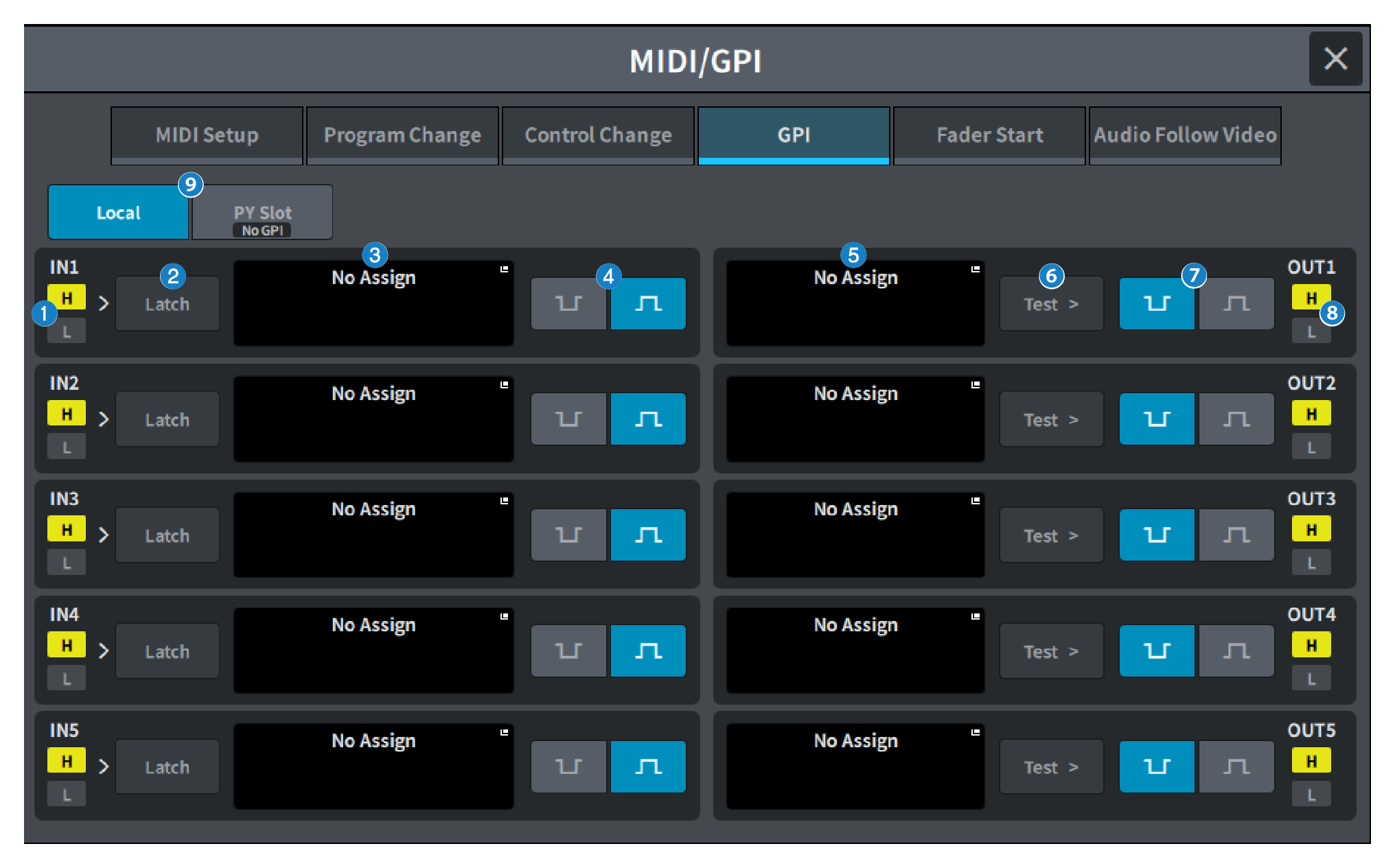
a | GPI IN status indicator Displays the status of the voltage input to the GPI IN port. |
b | Switch attribute selection button Each time this is pressed, the display switches between Latch and Unlatch.
|
c | GPI INPUT button Press this button to display the GPI INPUT screen The button displays the name of the currently-selected function or parameter. |
d | POLARITY MODE select button This button selects the polarity of the GPI IN port.
|
 …… (Low active) Becomes active when the input signal is low level.
 …… (High active) Becomes active when the input signal is high level.
e | GPI OUTPUT button Press this button to display the GPI OUTPUT screen. The button displays the name of the currently-selected function or parameter. |
f | TEST button While this button is on, the corresponding GPI OUT port will become active and outputs a control signal. |
g | POLARITY MODE select button Allows you to select the polarity of the GPI OUT port.
|
h | GPI OUT status indicator Indicates the status of the voltage that is being output from each GPI OUT port. |
i | Local/PY Slot Switches the display of the GPI setting target. Simultaneous operation is possible. |