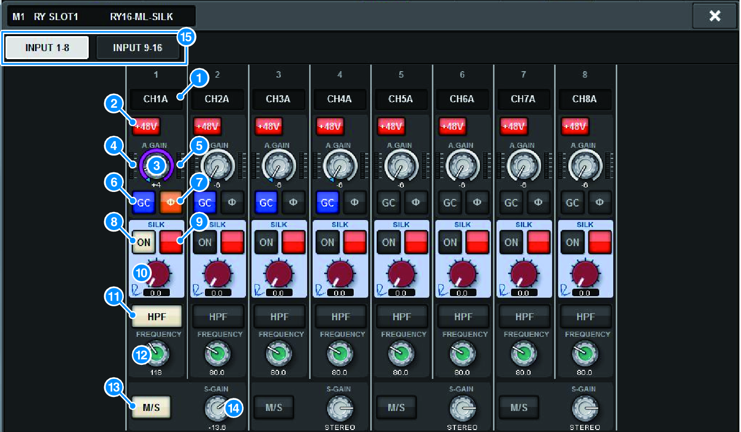
Editing the internal parameters of the RY16-ML-SILK

This screen contains the following items.
a | Patch indication Indicates the channel that is patched. |
b | +48V button Switches phantom power (+48V) on or off. |
c | A.GAIN knob Indicates the HA analog gain setting. Use the screen encoder to adjust the value. If gain compensation is on, an indicator shows the analog gain position at the time that gain compensation was turned on. |
d | Meter (Pre GC) This meter indicates the level of signals after passing through analog gain (before GC). |
e | Meter (channel input) This meter indicates the level after passing through GC (before D.GAIN). |
f | GC (GAIN COMPENSATION) button Switches the gain compensation on or off for that channel. |
g | PHASE button Switches the phase of the input signal. NOTE
|
h | SILK ON button Switches Silk on or off. |
i | RED/BLUE selection button Toggles between BLUE and RED: “BLUE” for solidity and power, and “RED” for sparkling energy. |
j | SILK [TEXTURE] knob Adjusts the TEXTURE parameter of Silk. |
k | HPF button Toggles the high pass filter on or off for each port. NOTE
|
l | FREQUENCY knob Sets the HPF cutoff frequency. |
m | M/S button Switches the M/S decoder on or off for each pair of channels. |
n | S-GAIN knob Adjusts the side gain of M/S. |
o | Tabs Switch the display in units of eight channels. |


 RIVAGE PM Series