

Signal flow within the RPio
The following diagram shows the signal flow within the RPio.
■Mode 1
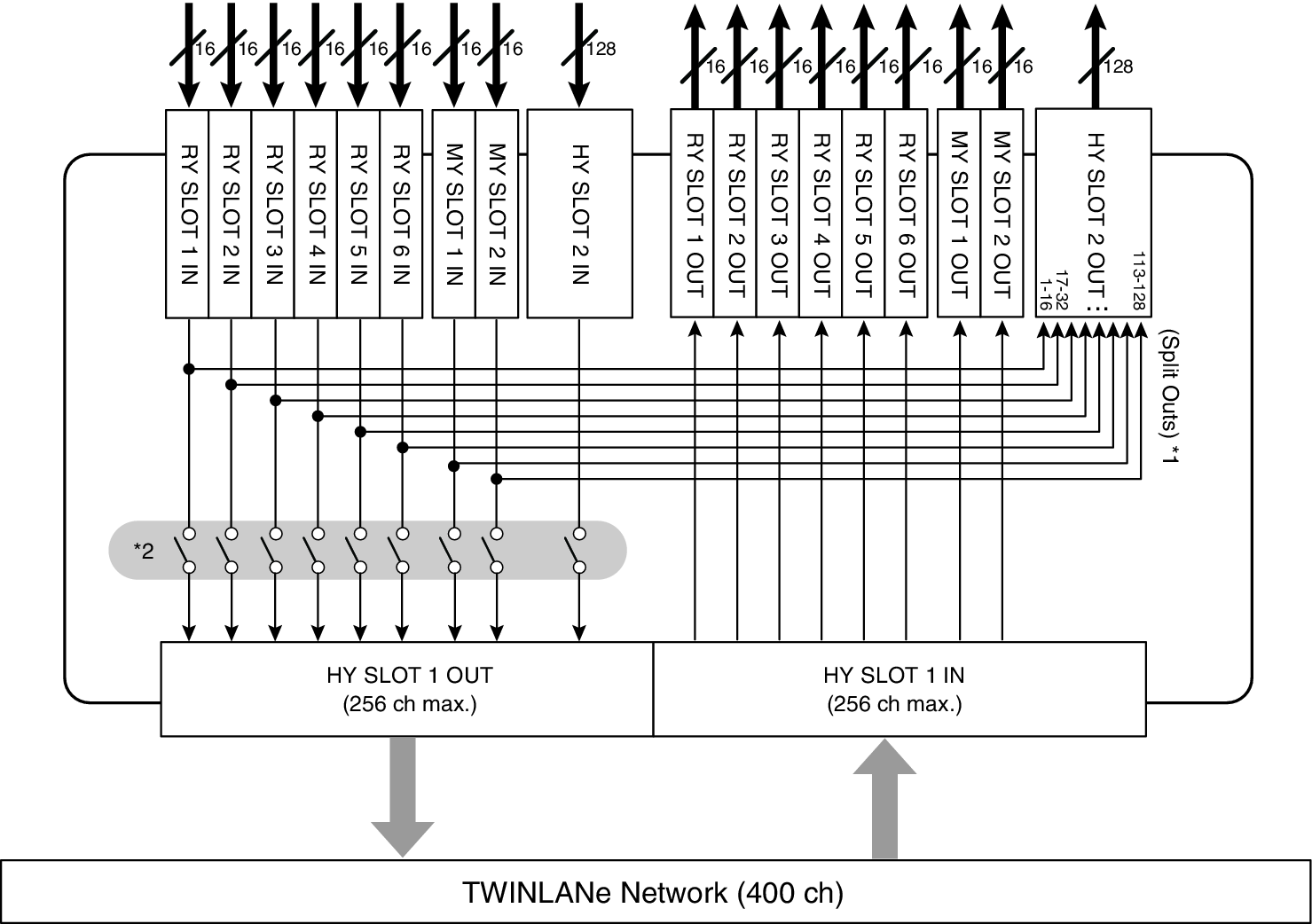
*1) In mode 1, all input signals (total 128 channels) of the RY slots and MY slots are always split for output to the HY SLOT 2 output. The signal is output immediately after gain compensation.
*2) Specifies the number of channels that are output to the TWINLANe network (turn on/off in 16-channel units for each slot).
■Mode 2
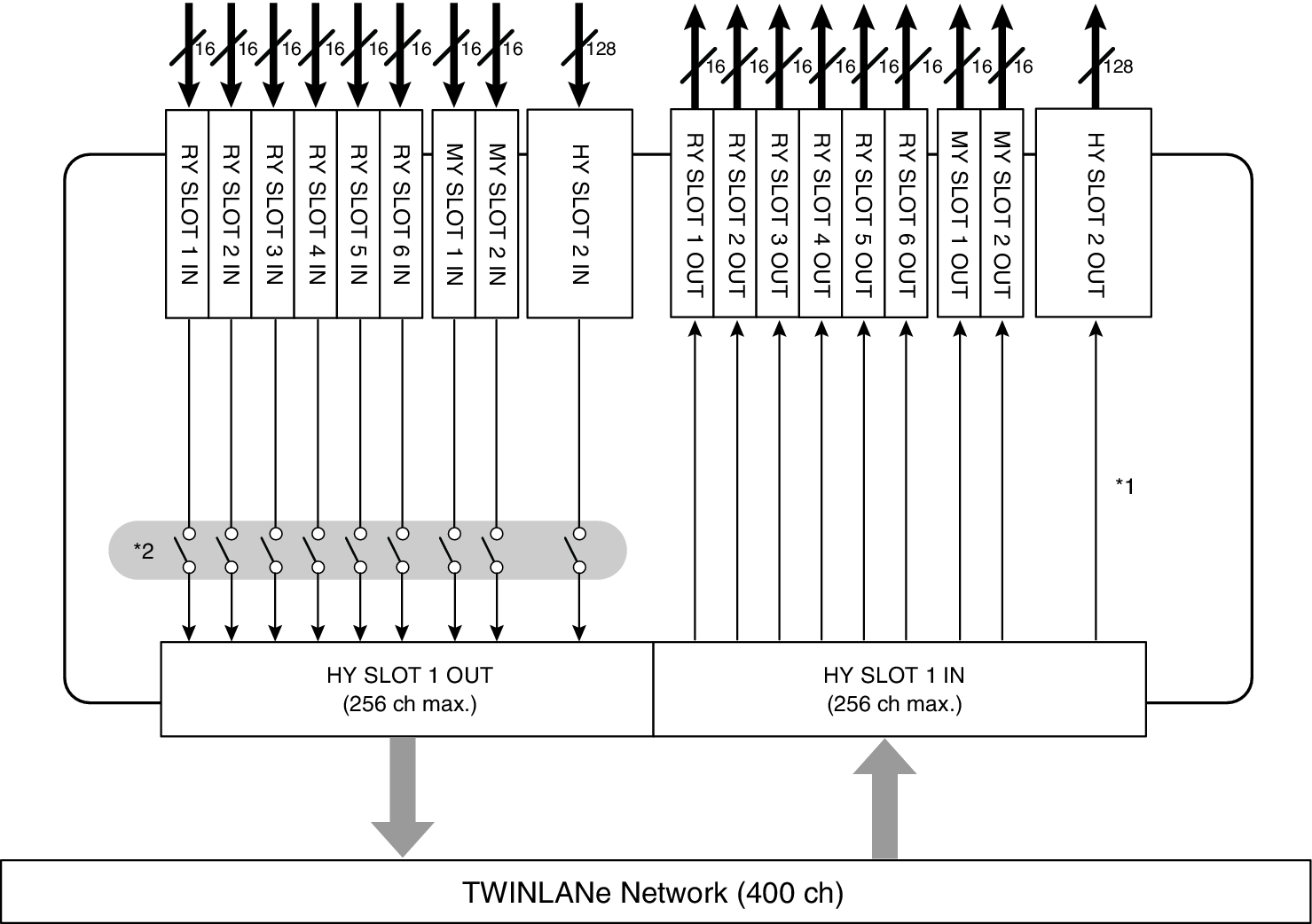
*1) In mode 2, you can patch signals from the DSP engine to the HY SLOT 2 output via the TWINLANe network.
*2) Specifies the number of channels that are output to the TWINLANe network (turn on/off in 16-channel units for each slot).