

SIGNAL FLOW popup window
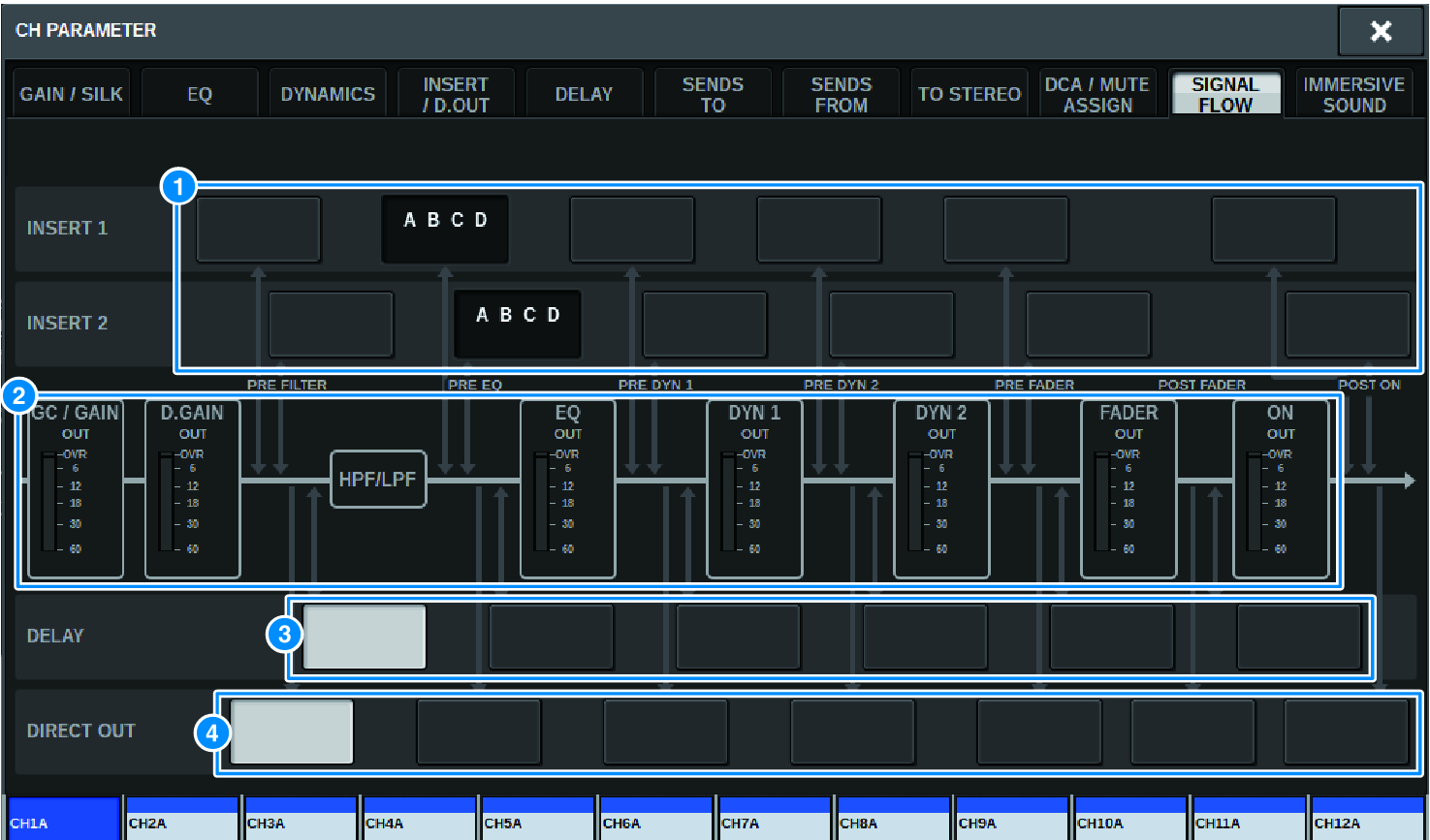
This window contains the following items.
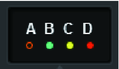
a | Insert point select buttons Enable you to select insert points. The following indicators indicate the status of the corresponding insert point: | |
| ||
| A plug-in, GEQ/PEQ, or outboard unit is inserted at the insert point. | |
| Bypassed. | |
| Level indicator Green:–18 dB or lower Yellow:higher than –18 dB to 0 dB or lower Red:higher than 0 dB and clipping | |


b | Level meters These meters indicate the levels at various points in the signal flow. Levels are detected at the following locations. INPUT
OUTPUT
|
c | DELAY POINT select buttons (input channels only) Enable you to select the delay insert point. |
d | DIRECT OUT POINT select buttons (input channels only) Enable you to select the direct out point. |