

DYN1 (GATE/DUCKING) screen
The DYN1 screen can be used to correct the dynamic range of each channel.
When GATE is selected, if the input signal level is lower than the threshold, the output signal is reduced by a specified amount (Range). When DUCKING is selected, if the input signal level is lower than the threshold, the output signal is reduced by a specified amount (Range). DYN1 is available for CH 1–16.
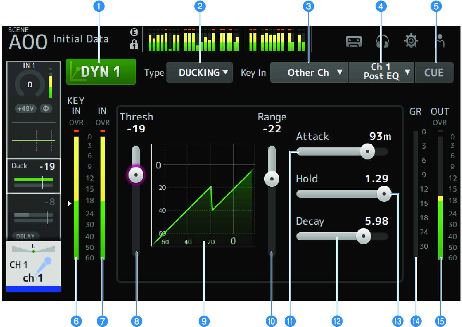
a | DYN1 button Turns the DYN1 function ON/OFF. |
b | Type selection button Selects either GATE or DUCKING. |
c | Key In selection button Select the Key In signal from the following.
|
d | Key In channel selection button It is enabled when Other Ch or MIX are selected by the Key In selection button. When Other Ch is selected, select from CH 1-16 Post EQ. When MIX is selected, select from MIX OUT 1-6. |
e | CUE button Turns the Key In signal CUE ON/OFF. |
f | DYN1 Key In level meter Displays the Key In input level. |
g | DYN1 input level meter Displays the DYN1 input level. |
h | Threshold slider Determines the level at which the GATE/DUCKING effect is applied. |
i | GATE/DUCKING graph Displays a visual representation of the GATE/DUCKING level. |
j | Range slider Determines the amount by which the signal will be lowered when GATE/DUCKING is applied. |
k | Attack slider When GATE is selected, this sets the time from when the input signal exceeds the threshold level until the gate opens. When DUCKING is selected, this sets the time from when the input signal exceeds the threshold level until the gate closes. |
l | Decay slider When GATE is selected, this sets the time until the gate closes after the input signal has passed the HOLD waiting time. When DUCKING is selected, this sets the time until the gate opens after the input signal has passed the HOLD waiting time. The setting value expresses the time required for the level to change by 6 dB. |
m | Hold slider When GATE is selected, this sets the waiting time until the gate starts to close after the input signal falls below the threshold level. When DUCKING is selected, this sets the waiting time until the gate starts to open after the input signal falls below the threshold level. |
n | GR (gain reduction) meter Displays the amount by which the signal's gain is reduced. |
o | OUT (output) meter Displays the GATE/DUCKING output level. |
DYN1 screen menu
Swipe left on the menu swipe indicator on the right of the DYN1 screen to open the following menu.

a | Copy Copies the DYN1 parameters of the selected channel. |
b | Paste Pastes the copied DYN1 parameters to the selected channel. |
c | Compare Allows you to compare the DYN1 parameters of the selected channel with the copied DYN1 parameters by switching between the two. |
d | Default Resets DYN1 settings to their default values. |