Power Amplifier XMS Series
1. Overview
The XMS series is a multi-channel power amplifier ideal for sound systems and commercial spaces. Equipped with a "power sharing" function that allocates power to each channel, this series can efficiently drive a large number of different speaker types. The internal DSP enables mixing, routing, and speaker processing of input signals. Dante models are available and you can build digital systems as well.
2. "Project" sheet
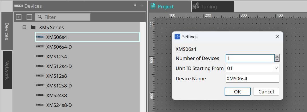
This is the sheet where you place devices. When placing a device, the Settings screen below will appear.
-
Number of Devices
Select the number of devices to be placed on the sheet. -
Unit ID Starting From
You can select the starting number for the Unit IDs of devices. -
Device Name
You can view and edit the device name.
3. Speaker connection
You can connect the XMS series to any speaker and view the speaker processor parameters for each speaker. For details, refer to "PC-D and speaker connections" in the PC series documentation.
4. "Properties" area
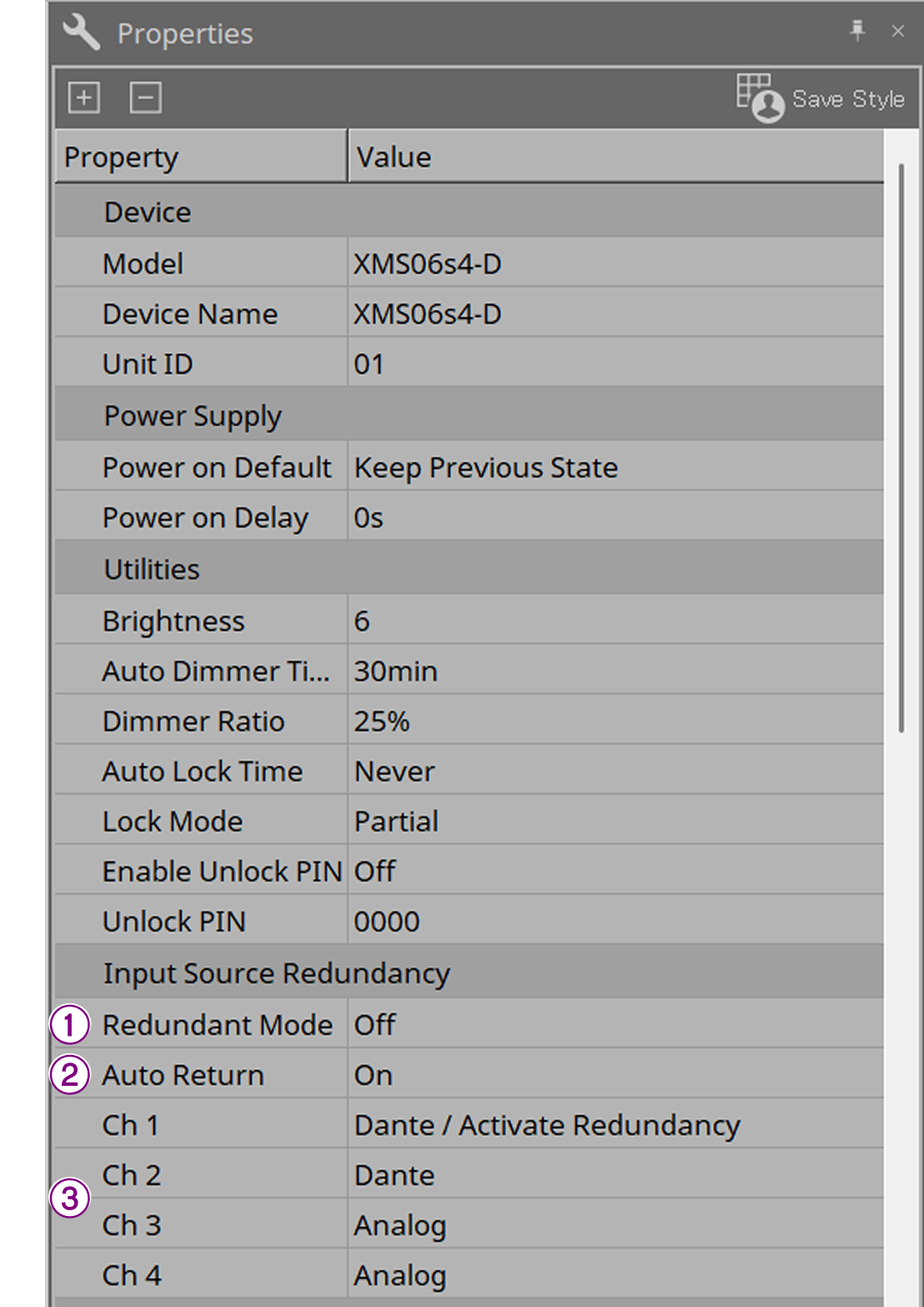
You can view and edit device information. This section explains "Input Source Redundancy" (Dante model only). For other settings, refer to the XMS series reference manual.
-
Input Source Redundancy
This setting determines whether the input source for each XMS channel is digital (Dante) or analog.Additionally, when the main line is set to digital, this setting configures the system to switch the input from digital to analog when the digital signal is lost or when an analog audio is detected.
| Input Source Redundancy is a function independent of the Dante network’s redundancy function. |
① Redundant Mode
You can change the redundancy method for channels 1 to 4 simultaneously.
-
[Off]
Disables redundancy. -
[Backup]
Switches to analog input when the digital input is interrupted due to a problem such as a broken wire. -
[Override]
Switches to analog input when analog audio is detected.
② Auto Return
When set to On, the input automatically switches back to digital when the digital line is restored.
③ Ch 1 to 4
Clicking  displayed when you click the Value field opens the "Input Source Redundancy" dialog box.
4.1. "Input Source Redundancy" dialog box
Detailed redundancy settings can be configured on a per-channel basis.
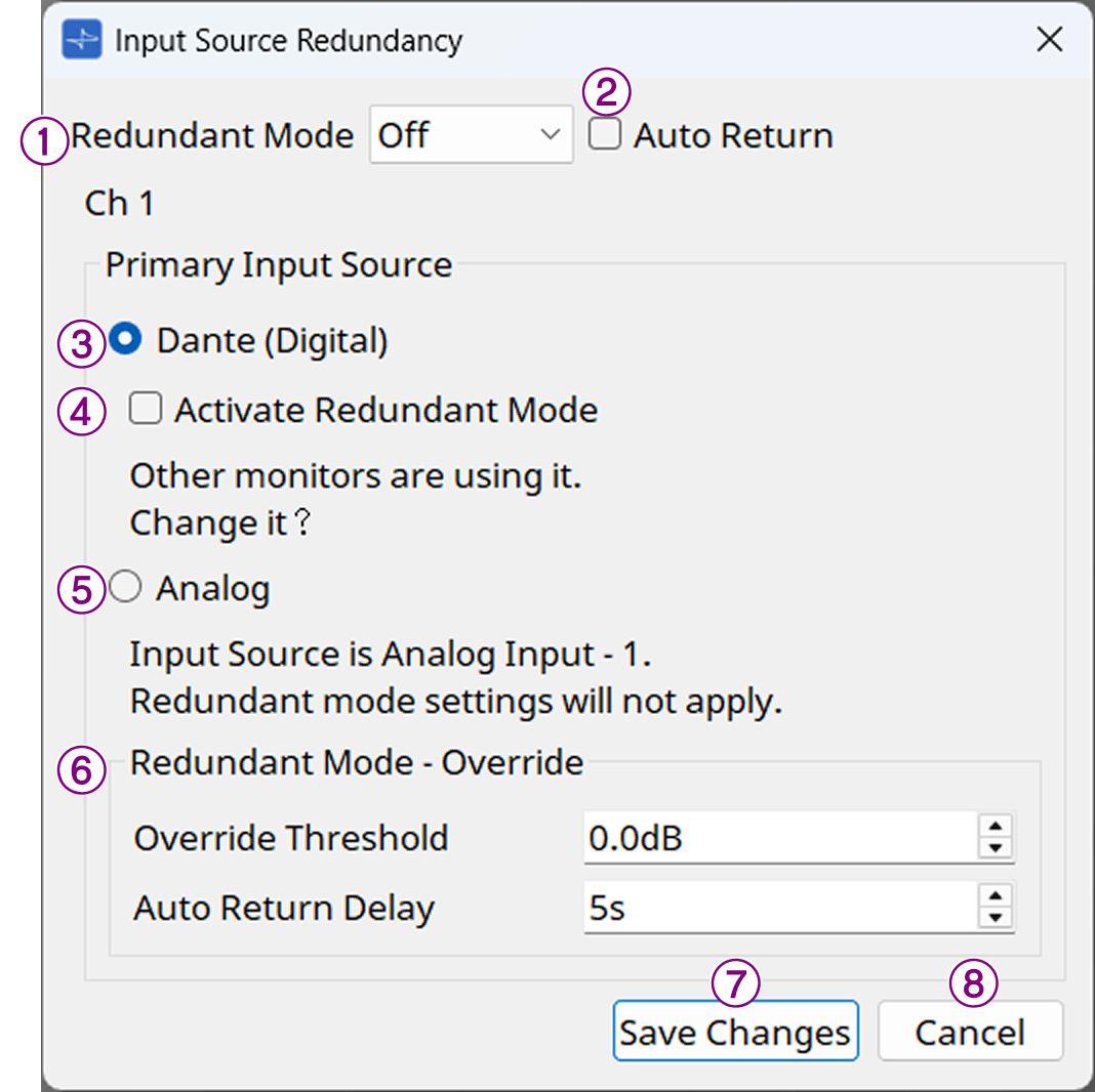
① [Redundant Mode] list box
Select the redundancy method.
-
[Off]
Disables redundancy. -
[Backup]
Switches to analog input when the digital input is interrupted due to a problem such as a broken wire. -
[Override]
Switches to analog input when analog audio is detected.
② [Auto Return] check box
When this check box is selected, the following applies.
-
In Backup mode
When the digital input is restored, the input source switches from analog to digital. -
In Override mode
When the analog input falls below a threshold, the input source switches back from analog to digital.
"Primary Input Source" area
You can switch between digital and analog inputs on a per-channel basis.
③ [Dante (Digital)] radio button
The signals for the corresponding channel are retrieved from Dante.
Configure Dante patches in the Dante Controller.
④ [Active Redundant Mode] check box
Select this check box to enable the redundancy function.
The redundant mode is determined by the [Redundant Mode] list box. If [Off] is selected, the redundancy function remains disabled regardless of whether this check box is selected.
⑤ [Analog] radio button
Signals are retrieved from the analog input jack of the corresponding channel.
⑥ "Redundant Mode - Override" area
You can set the conditions for switching to analog input in Override mode on a per-channel basis.
-
[Override Threshold] spin box
Sets the threshold for analog input. The input source switches to analog when the threshold is exceeded.
This item is only valid when [Override] is selected in the [Redundant Mode] list box. -
[Auto Return Delay] spin box
When the [Auto Return] check box is selected, this item sets the delay time from when the analog input is determined to have fallen below the threshold to when the input source switches to digital.
⑦ [Save Changes] button
Saves the settings and closes the dialog box.
⑧ [Cancel] button
Discards the changes to the settings and closes the dialog box.
5. "Tuning" sheet
The "Tuning" sheet allows you to set parameters (such as EQ and delay) for grouped channels simultaneously. For details on the sheet, refer to "Tuning" sheet. For explanations of the editor screen, refer to "Tuning" sheet in the PC series documentation.
6. Screen structure of device sheet
When you open the device sheet, the "Presets" area and the "Bird’s Eye view" area displayed.
Double-click a component on the device sheet to open the component editor.
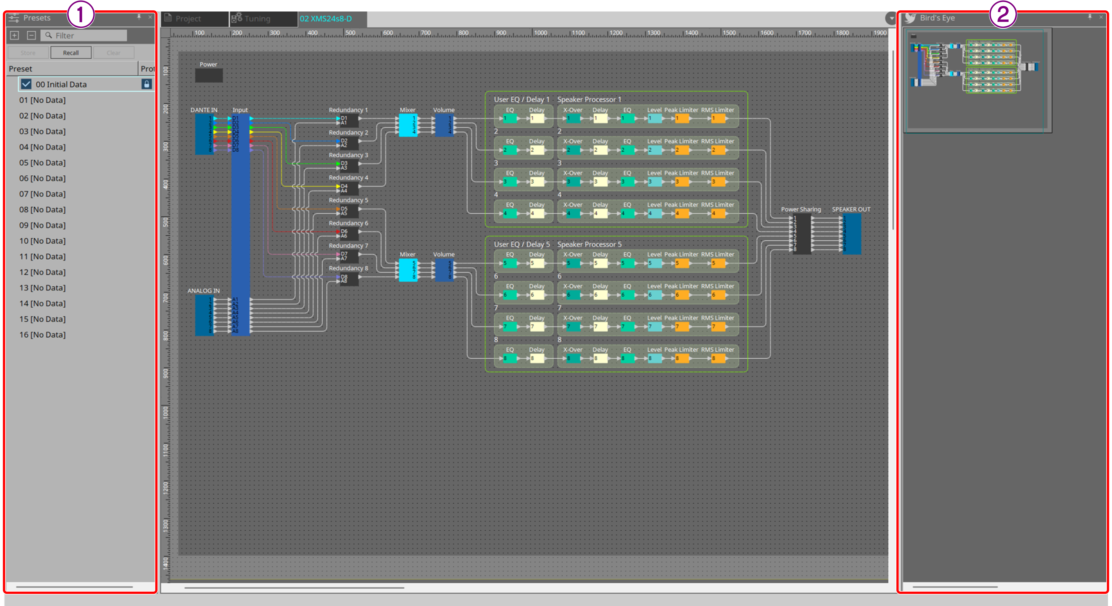
① "Presets" area
You can store settings for multiple parameters as presets.
② Bird’s Eye view
Shows the entire view of the sheet.
7. "Presets" area
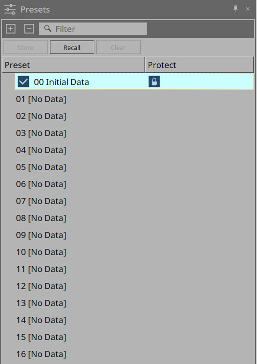
In this area, you can store settings for multiple parameters as presets, and recall them to apply the parameters within those presets. Parameters of the applied preset are called the current parameters.
To recall presets for multiple devices simultaneously, click the  button and configure the settings in the "Linked Presets Manager" dialog box.
-
[Store] button
This button is used to store presets. -
[Recall] button
This button is used to recall presets. -
[Clear] button
This button is used to clear presets. -
Preset list
Shows a list of presets. You can store up to 16 presets.-
"Preset"
This column displays the number and name of the preset. Expanding a preset allows you to select which parameters to include in the recall target.
Select a stored preset and double-click this area to edit its name.
The name of an empty preset will be displayed as [No Data]. -
"Protect"
Clicking the padlock icon changes the icon to
  and protects the preset from being edited or cleared.
Clicking the icon while the preset is protected removes the protection. -
00 Initial Data
Resets to default settings. This is a recall-only preset.
-
8. Context menu
The following shows the context menu items that appear when you right-click on each area.
8.1. "Tuning" sheet
Right-click on the "Tuning" sheet to display the following context menu items.
| Menu | Meaning |
|---|---|
[Select All] |
Selects all link groups on the [All Link Groups] sheet. |
[Close All Editor Windows] |
Closes all editors. |
[Snap to Grid] |
When selected, objects are snapped to the grid on the sheet. |
8.2. Link groups on the "Tuning" sheet
Right-click a link group to display the following context menu items. Some menu items may not be available depending on the connected device.
| Menu | Meaning |
|---|---|
[Open Link Group Editor] |
Opens the link group editor. For the link group editor, refer to the documentation for each device. |
[Open Device Sheet] |
Opens the device sheet for the selected device. |
[Identify] |
The indicator on the device flashes for a few seconds. |
[Delete] |
If a channel is selected, it is removed from the link group. |
[Bring to Front] |
Moves the link group to the foremost position. |
[Send to Back] |
Moves the link group to the rearmost position. |
8.3. "Project Devices" area
Right-click a device or channel in the "Project Devices" area to display the following context menu items.
| Menu | Meaning |
|---|---|
[Find] |
Focuses on the link group to which the devices and channels are registered. |
[Add to Link Group] |
Registers the device’s channel to the link group. If a speaker is connected to the device, the channel of the connected device is registered. |
8.4. "Link Groups" area
Right-click an object in the "Link Groups" area to display the following context menu items.
| Menu | Meaning |
|---|---|
[Find] |
Right-clicking on a device focuses on the device within the link group and opens the link group component editor. |
[Delete] |
Right-clicking on a channel removes it from the link group. |
8.5. Device sheet
Right-clicking on a device sheet in an area without objects displays the following context menu items.
| Menu | Meaning |
|---|---|
[Close All Editor Windows] |
Closes all editors. |
8.6. Components within the device sheet/Component editor
Right-clicking a component or anywhere outside of its controls displays the following context menu items (the items to be displayed vary depending on the situation).
| Menu | Meaning |
|---|---|
[Open Component Editor] |
Opens the component editor. |
[Copy] |
Copies the parameter settings from the component editor. |
[Paste Parameters] |
Applies the parameter settings from the copied component editor. |
9. Alert list
The following table lists the alerts generated by the XMS series, along with their meaning and countermeasures.
If the problem persists, contact the repair consultation center listed at the back of the instruction manual for the device.
| Number | Message | Severity | Meaning | Countermeasure |
|---|---|---|---|---|
0 - 9 |
SYSTEM ERROR |
- |
The product is not starting up properly. |
The product may be faulty. Contact your Yamaha dealer. |
10 |
POWER SUPPLY 1 OUTPUT VOLTAGE LIMIT |
Error |
The amplifier has stopped due to an error in the output voltage of the power supply circuit. |
The product may be faulty. Contact your Yamaha dealer. |
11 |
POWER SUPPLY 2 OUTPUT VOLTAGE LIMIT |
Error |
||
12 |
POWER SUPPLY 1 OVER-TEMPERATURE |
Error |
The amplifier has stopped due to the power supply unit overheating. |
・Lower the room temperature. |
13 |
POWER SUPPLY 2 OVER-TEMPERATURE |
Error |
||
14 |
CH.1-4 MUTED - DC OUTPUT |
Fault |
The DC output of the amplifier has been detected, so the product has been shut down. |
The product may be faulty. Contact your Yamaha dealer. |
15 |
CH.5-8 MUTED - DC OUTPUT |
Fault |
||
16 |
CH.1-4 OVER-TEMPERATURE LEVEL 1 |
Warning |
The amplifier has become too hot, so the output limiter has been applied. |
・Reduce the output level. |
17 |
CH.1-4 OVER-TEMPERATURE LEVEL 2 |
Error |
The amplifier has become too hot, so the output has been muted. |
|
18 |
CH.1-4 OVER-TEMPERATURE LEVEL 3 |
Error |
The amplifier became too hot and was shut down. |
|
19 |
CH.5-8 OVER-TEMPERATURE LEVEL 1 |
Warning |
The amplifier has become too hot, so the output limiter has been applied. |
|
20 |
CH.5-8 OVER-TEMPERATURE LEVEL 2 |
Error |
The amplifier has become too hot, so the output has been muted. |
|
21 |
CH.5-8 OVER-TEMPERATURE LEVEL 3 |
Error |
The amplifier became too hot and was shut down. |
|
22 |
CH.1-4 OUTPUT CURRENT LIMIT |
Error |
The output was muted due to an overcurrent flowing through the amplifier of the relevant channel. |
・ Suppress the output volume to prevent the current from becoming too high. |
23 |
CH.5-8 OUTPUT CURRENT LIMIT |
Error |
||
30 |
DANTE MODULE IN FAIL SAFE MODE |
Warning |
The built-in Dante module is in Fail Safe mode. |
The firmware of the Dante module was not written correctly due to a failed update or other reason. Select Safe mode in Dante Updater and rewrite the code. |
31 |
DANTE MODULE FAILED |
Fault |
The Dante module is not working properly. |
The product may be faulty. Contact your Yamaha dealer. |
32 |
DANTE PORT NOT CONNECTED |
Warning |
Neither the Primary nor Secondary line is connected to the Dante network. |
Confirm that the Dante lines are properly connected. |
33 |
DANTE NOT USING 1Gbps LINK |
Warning |
A device that does not support Gigabit Ethernet is connected. |
When using Dante for voice transmission, use equipment that supports Gigabit Ethernet. |
34 |
DANTE DEVICE NOT FOUND |
Warning |
The Dante device to be patched could not be found. |
Check the Dante connections. |
35 |
WRONG WORD CLOCK |
Warning |
The Dante word clock setting is incorrect. |
Check the Dante word clock settings. |
36 |
MUTED DUE TO WRONG DANTE CLOCK |
Error |
The Dante word clock is muted because the settings are incorrect. |
Check the Dante word clock settings. |
37 |
DANTE CLOCK OFFSET UNSTABLE |
Warning |
The Dante clock frequency offset is unstable. |
Check the network configuration, including the settings of the Ethernet switch. |
38 |
DANTE USING SECONDARY PORT |
Warning |
Dante audio transmission has been switched to the secondary network. |
Confirm that the Dante lines are properly connected. |
39 |
ERROR OCCURRED AT SECONDARY PORT |
Warning |
When using a redundant network, an error occurred on the line connected to the Secondary port. |
If a secondary line connection is required, check for abnormalities. |
40 |
INPUT D[*] CHANGED TO A[*] |
Warning |
The audio of the D[*] channel has been switched to the analog line by |
Please check if there are any issues with the main audio line (Dante). (If the AutoReturn function is ON, please note that reconnecting may cause the line to switch suddenly.) |
41 |
INPUT D[*] RETURNED |
Warning |
In the Input Redundancy function, the audio has returned to D[*] channel.(*: 1 to 8) |
- |
42 |
NETWORK LINK UNSTABLE |
Warning |
The network cable connection to the product is unstable. |
Check the cable connections and network status. |
43 |
ILLEGAL MAC ADDRESS |
Fault |
An invalid MAC address was detected on the Ethernet control interface. |
Contact your Yamaha dealer. |
50 |
POWER ON |
None |
The power has been turned on. |
- |
51 |
POWER OFF |
None |
The power has been turned off. |
- |
52 |
MOMENTARY POWER INTERRUPTION DETECTED |
Warning |
A momentary power interruption has been detected. |
Connect to a stable power source. |
53 |
DEVICE INITIALIZED |
None |
Initialization has been completed. |
- |
54 |
TIME SYNCHRONIZED |
None |
The time has been synchronized. |
- |
55 |
FIRMWARE UPDATED |
None |
The firmware has been updated. |
- |
56 |
[*]: PRESET STORE |
None |
Preset stored (*: preset number). |
- |
57 |
[*]: PRESET RECALL |
None |
Preset recalled (*: Preset number). |
- |
58 |
PANEL UNLOCKED |
None |
The panel is now unlocked. |
- |
59 |
PIN CODE CHANGED |
None |
The PIN code has been changed. |
- |
60 |
INCORRECT PIN CODE |
Warning |
An incorrect PIN code was entered. |
- |
61 |
FIRMWARE VERSION MISMATCH |
Error |
The firmware version of this product and the firmware version of Dante are not compatible. |
The updater available on the web includes firmware for both the main device and Dante as a set. Please update both. |
62 |
UNIT ID MISMATCH |
Error |
The UNIT ID and Dante Device Label do not match. |
Remove any restrictions imposed by the Dante Device Lock or Dante Domain Manager functions before changing the UNIT ID. |
63 |
INPUT OVERRIDDEN |
None |
The system has switched to the higher-priority input line. |
- |
64 |
ENTERED SLEEP MODE |
None |
The product has entered sleep mode. |
- |
65 |
EXITED SLEEP MODE |
None |
The product has exited sleep mode. |
- |
66 |
GPI OPERATED |
None |
The switch was operated via the REMOTE terminal on the rear panel. |
- |
10. Component editor
The component editor allows you to configure and adjust the settings for each component of the selected device.
Double-click a component on the device sheet to open the component editor.
This section describes the component editor for the XMS series and the dialog boxes and windows associated with components.
* Unless otherwise specified, the explanation uses screenshots from the Dante model.
For details on other components, refer to "ProVisionaire Design Component Guide."
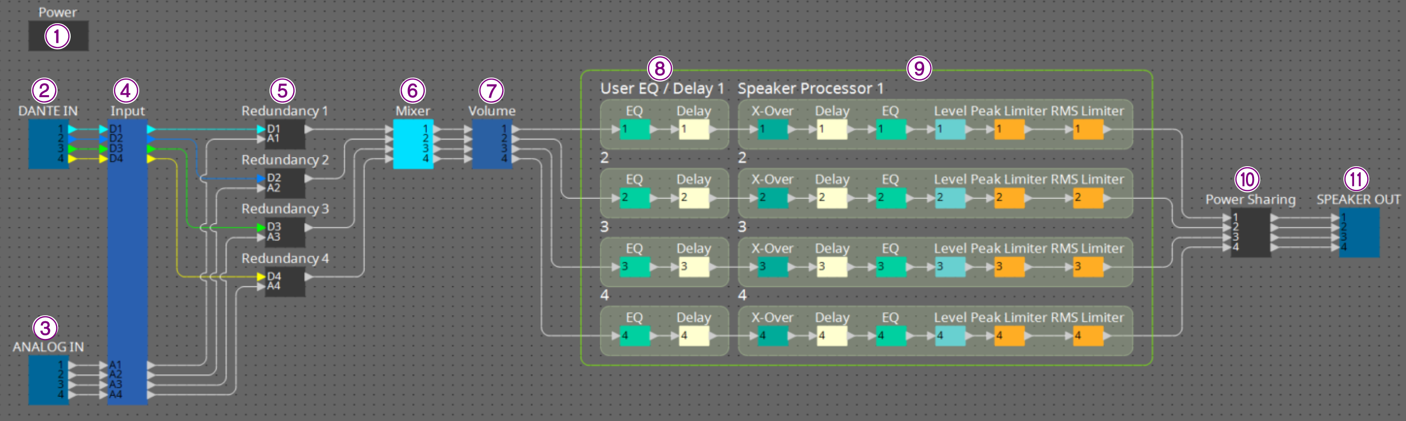
Dante model
Standard model
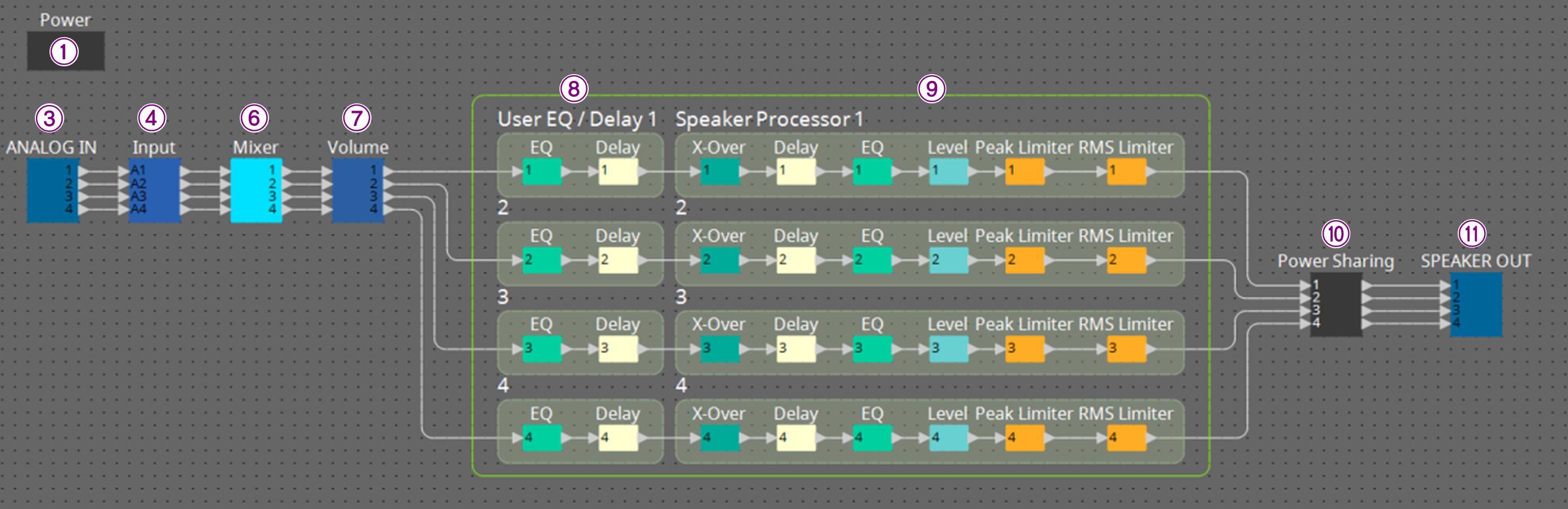
| Number | Component name | Content | Link |
|---|---|---|---|
① |
Power |
Toggles the device’s sleep mode on and off, and also toggles the device’s mute function on and off. |
|
② |
DANTE IN |
Displays the input settings for the [Dante] jack and the level of the input audio signal. |
|
③ |
ANALOG IN |
Displays the input settings for the [INPUT] jack and the level of the input audio signal. |
|
④ |
Input |
Adjusts input channel levels and displays their status. |
|
⑤ |
Redundancy |
Configures input sources and override/backup behavior on a per-channel basis. |
--- |
⑥ |
Mixer |
Configures the routing of the audio signal. |
--- |
⑦ |
Volume |
Adjusts output channel levels and controls muting and phase switching. |
--- |
⑧ |
User EQ/Delay |
Configures the EQ/delay for the output channel. |
|
⑨ |
Speaker Processor |
Configures the speaker processor for the output channel. |
|
⑩ |
Power Sharing |
Distributes the output to each output channel. |
|
⑪ |
SPEAKER OUT |
Displays the output voltage and output current of the speaker output jack. |
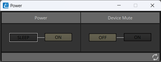
10.1. "Power" component editor
-
Power
-
[SLEEP]/[ON] button
Toggles between power standby and power-on.
-
-
Device Mute
-
[OFF]/[ON] button
Toggles Device Mute of the device on or off.
When set to ON, the speaker output of all channels on the amplifier is muted.
-
10.2. "Input Alignment" component editor
This editor appears when you double-click the "DANTE IN" or "ANALOG IN" component. It displays the settings related to the input jack and the level of the input audio signal.
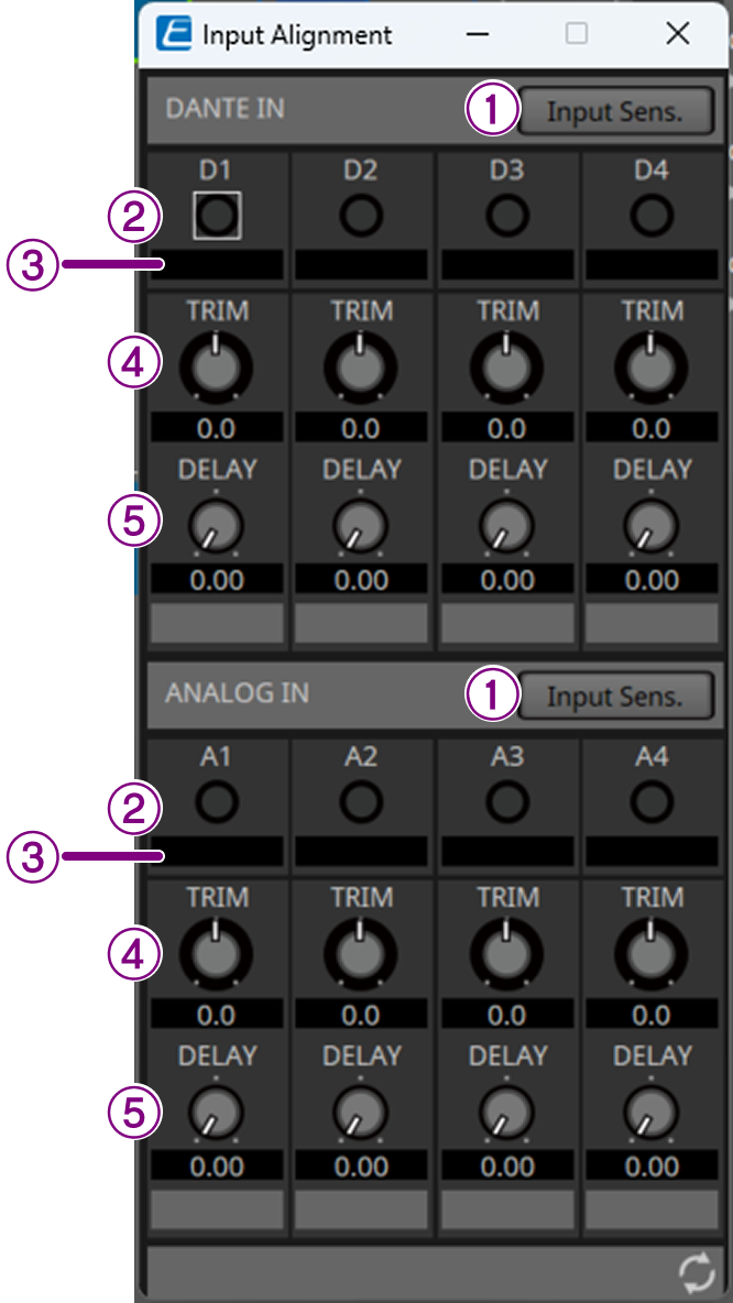
① [Input Sens.] button
Dante model: Opens the "Dante Input Sens. & Analog Input Sens. /Gain" dialog box.
Analog model: Opens the "Analog Input Sens./Gain" dialog box.
② Input indicator
The DANTE IN area displays the levels after correction using the [Input Sens.] button > [Digital Input Sens.].
The ANALOG IN area displays the levels after correction using the [Input Sens.] button > [Analog Input Sens.].
③ Meter
This meter displays the level after correction using TRIM and DELAY.
④ [TRIM] knob
You can correct the level difference between input jacks.
⑤ [DELAY] knob
You can correct the latency difference between input jacks.
"Input Sens./Gain" dialog box
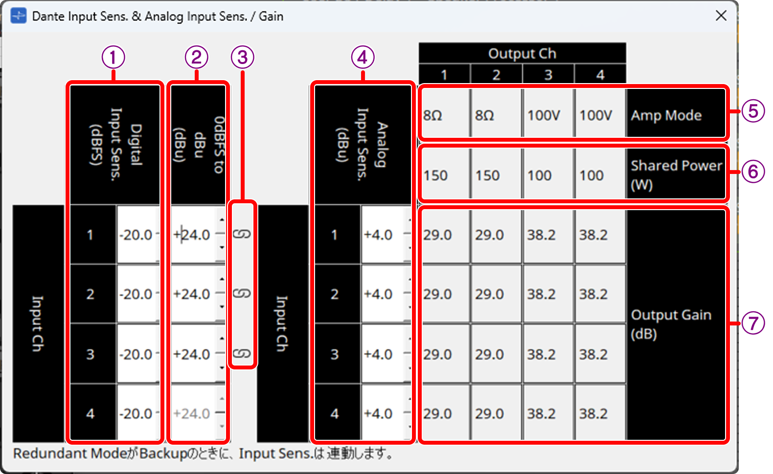
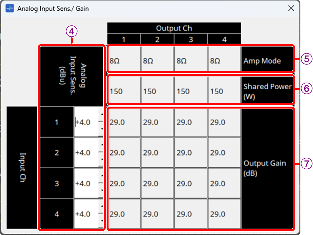
To open this box, double-click the "DANTE IN" or "ANALOG IN" component and click the [Input Sens.] button. You can view/change the input sensitivity for each channel.
"Dante Input Sens. & Analog Input Sens. /Gain" dialog box (Dante model)
"Analog Input Sens. /Gain" dialog box (Standard model)
① Digital Input Sens. (dBFS)
You can set the input sensitivity for the digital input.
② 0 dBFS to dBu (dBu)
You can set the analog input level in dBu that corresponds to 0 dBFS. Only channels with a link icon can be edited.
③ Link icon 
This icon is displayed on channels where the digital input and analog input are synchronized. When the following settings are configured in "Input Source Redundancy" in the "Properties" area, the sensitivity of digital and analog inputs are synchronized.
• Redundant Mode : Backup
・Primary Input Source : Dante(Digital)
・Activate Redundant Mode : ON
④ Analog Input Sens. (dBu)
You can set the input sensitivity of the analog input.
When you change the value, the output gain of each channel automatically changes to match the amplifier mode and maximum output. Channels with a link icon are synchronized with the digital input value.
⑤Amp Mode
The values set in [Amp Mode] of the Power Sharing Component Editor are displayed.
⑥Shared Power(W)
The values set in [Shared Power(W)] of the Power Sharing Component Editor are displayed.
⑦Output Gain(dB)
The output gain (dB) according to the input sensitivity is displayed.
10.3. "Input" component editor
This editor allows you to adjust the input channels and display their status.

① Redundant Status
This light illuminates when the system switches from the primary line (Dante) to the backup line (Analog).
② Return Availability
This light illuminates when the primary line is restored and the input line can be returned to the primary line. (Only when Auto Return = OFF)
③ [Return] button
When the primary line is restored, pressing this button allows you to manually switch the input line back to the primary line.
(Only when Auto Return = OFF)
|
When Auto Return is ON, the line is automatically restored. You can change the Auto Return setting in the Project sheet > Properties area > "Input Source Redundancy". |
10.4. "Power Sharing" component editor
The output is distributed to each channel according to the speakers in use.
The "Power Sharing" component editor allows you to enter information about the speakers in use and automatically configure the distribution.
10.4.1. Automatic calculation procedure
The following describes the procedure for automatically calculating the output value for each channel according to the speakers in use.
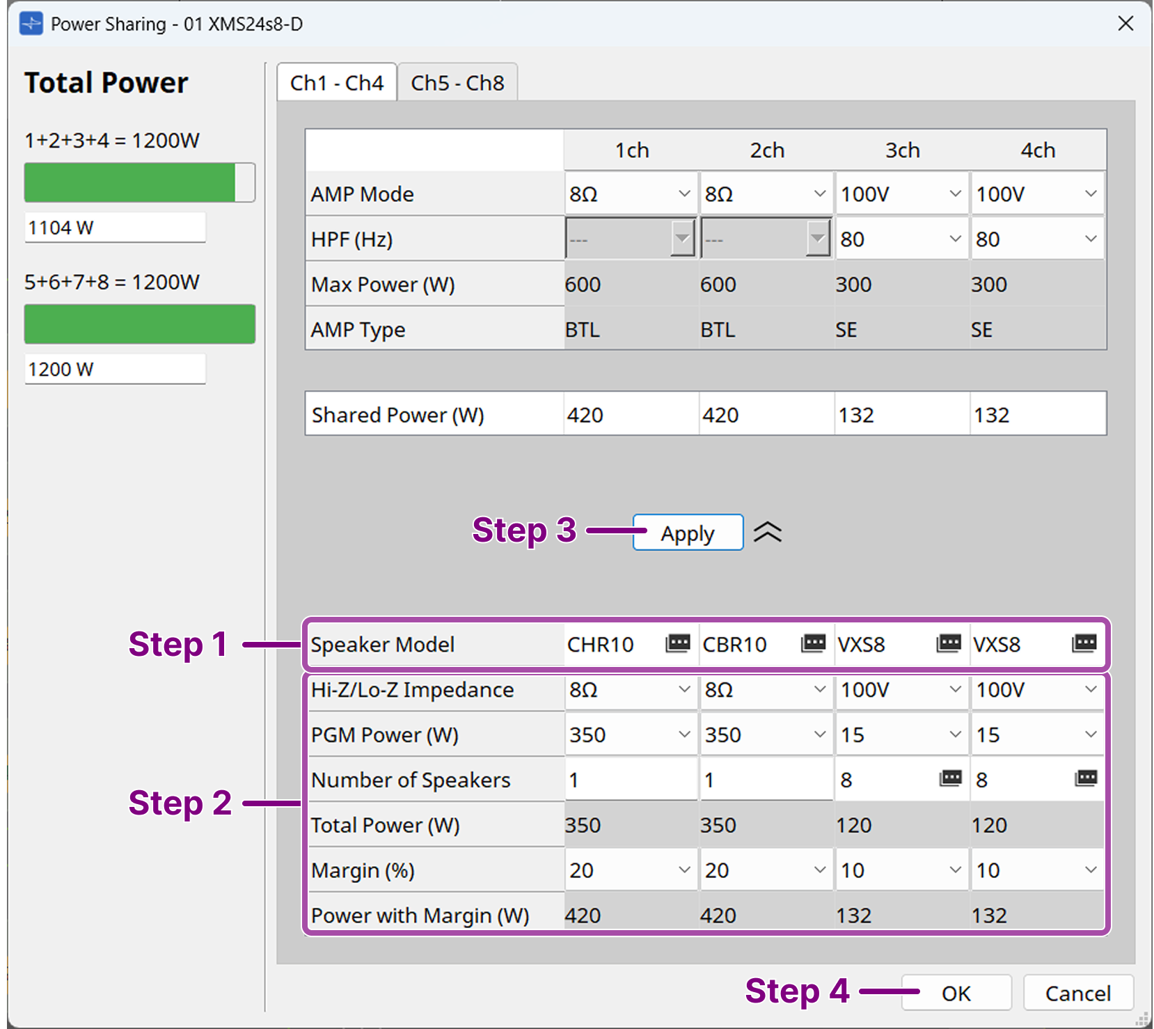
Step 1. Click in the [Speaker Model] field and select the speaker to connect to each channel.
When the speaker you want to use is listed, select it. Otherwise, select Generic.
Step 2. Enter the speaker specifications, number of units, and margin.
When you enter speaker information, the required wattage is displayed in [Power with Margin (W)]. Ensure that [Power with Margin (W)] does not exceed the [Max Power (W)] value on the upper section.
Step 3. Click the [Apply] button.
The information entered in the lower section is applied to the setting values. The information displayed in the upper section represents the final setting values of the device. You can also manually edit the setting values.
If the wattage exceeds the upper limit, the corresponding section will be displayed in red. Change the speaker information so that the wattage does not exceed the upper limit.
Step 4. Click the [OK] button to save the settings.
NOTE Maximum output per channel
| Model | XMS06s4 XMS06s4-D |
XMS12s4 XMS12s4-D |
XMS12s8 XMS12s8-D |
XMS24s8 XMS24s8-D |
|
|---|---|---|---|---|---|
Number of channels |
4 |
4 |
8 |
8 |
|
Total Power |
1Ch - 4Ch |
600 W |
1200 W |
600 W |
1200 W |
5Ch - 8Ch |
- |
- |
600 W |
1200 W |
|
Maximum output per channel |
Low impedance (4Ω/8Ω) |
300 W |
600 W |
300 W |
600 W |
High impedance (70V/100V) |
150 W |
300 W |
150 W |
300 W |
|
-
For 8-channel models, power cannot be distributed across channels 1 to 4 and channels 5 to 8.
10.4.2. Component editor
This editor allows you to configure the amplifier mode and output settings for each channel.
Items ③ to ⑦ are the setting values for the device. Items ⑨ to ⑮ are used for automatic calculation.
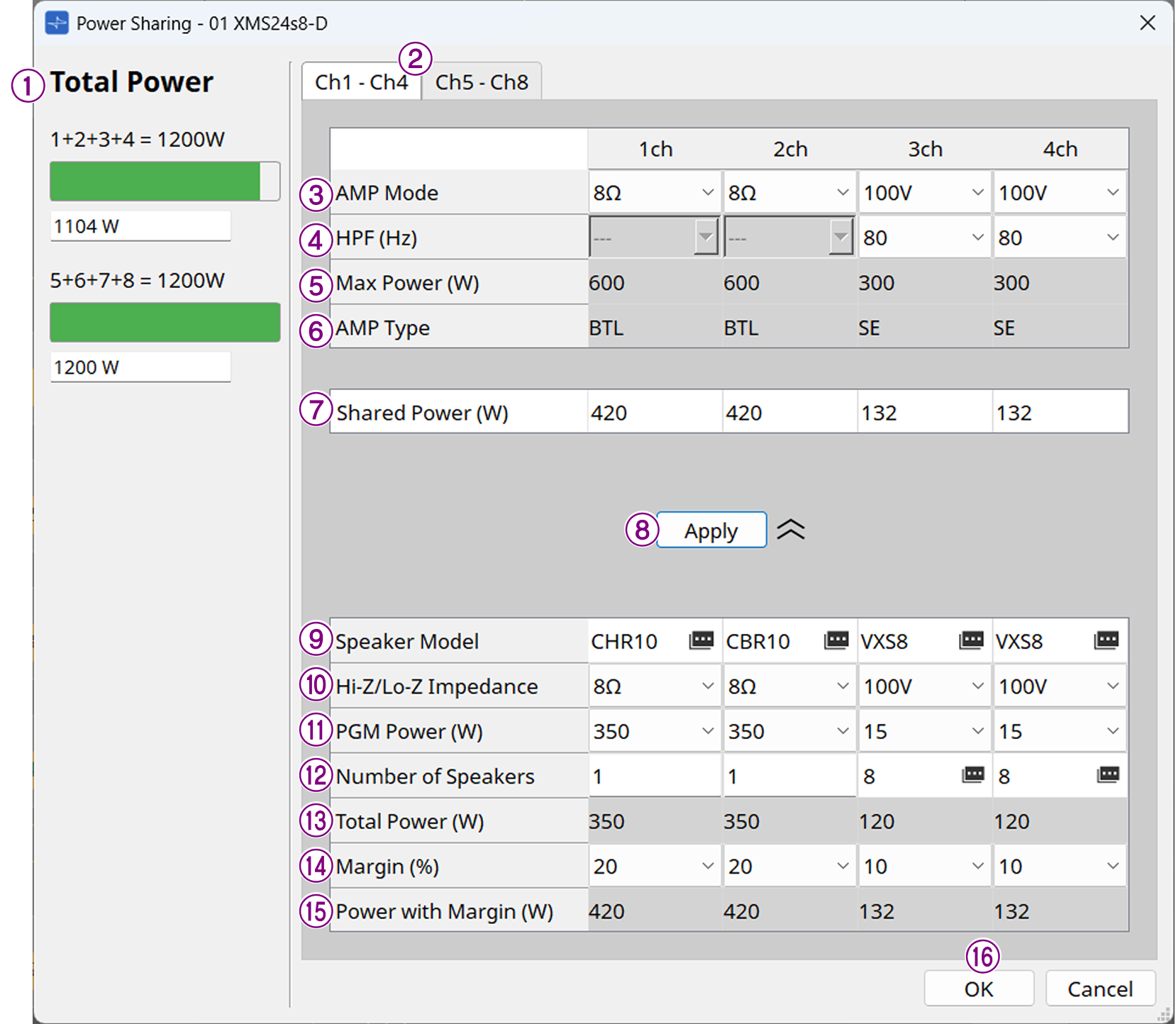
① Total Power
This area displays the upper limit and the total value of the current setting values for channels 1+2+3+4 and channels 5+6+7+8.
If the total value exceeds the upper limit, it will be displayed in red.
② Ch1 - Ch4/Ch5 - Ch8 tabs
You can switch the display between channels 1 to 4 and channels 5 to 8.
③ AMP Mode
Set a low-impedance connection (4Ω/8Ω) or a high-impedance connection (70V/100V).
Pressing the [Apply] button automatically applies the appropriate settings calculated from the speaker information. Manual editing is also possible.
④ HPF (Hz)
Set the high-pass filter. This setting is only available when AMP Mode is set to high-impedance connection (70V/100V). Pressing the [Apply] button automatically applies the appropriate settings calculated from the speaker information. Manual editing is also possible.
⑤ Max Power (W)
Displays the upper limit for the output for each channel.
⑥ AMP Type
Displays the internal connection of the amplifier (SE or BTL).
For SE and BTL, refer to the "XMS Series Reference Manual."
⑦ Shared Power (W)
Set the output for each channel.
Pressing the [Apply] button automatically applies the appropriate settings calculated from the speaker information. Manual editing is also possible. After automatic calculation using the [Apply] button, channels that exceed the maximum output are displayed in red.
⑧ [Apply] button
Applies the content entered in the lower section (⑨ to ⑮) to the settings in the upper section (③ to ⑦).
⑨ Speaker Model
Select the speaker to connect. Click to display the selection screen.
If the desired speaker is not available in the selection list, select "Generic" and manually enter the subsequent items.
⑩ Hi-Z/Lo-Z Impedance
Select the speaker impedance.
⑪ PGM Power (W)
Select the power handling capacity (PGM) for the speaker.
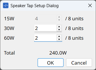
⑫ Number of Speakers
Set the number of speakers. For high-impedance connections with Yamaha speakers selected, clicking allows you to specify the number of speakers per TAP, using the number in the [Number of Speakers] field as the total.
⑬ Total Power (W)
Displays the total value up to this point.
⑭ Margin (%)
Set the margin to be applied to [Total Power].
⑮ Power with Margin (W)
Displays the value of [Total Power] plus the margin.
⑯ [OK] button
Saves the settings and closes the screen. If the sum of [Shared Power] for channels 1 to 4 or channels 5 to 8 exceeds [Total Power], or if [Shared Power] exceeds [Max Power], you cannot press the [OK] button.
10.5. "Speaker Out" component editor
This editor displays the output voltage and output current of the speaker output jack.
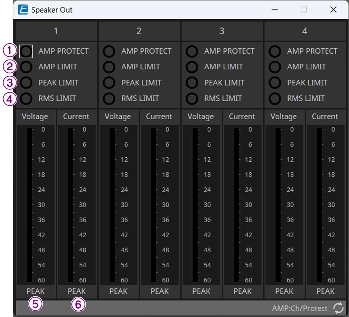
① [AMP PROTECT] indicator
Lights up when protection is active on the XMS series unit.
② [AMP LIMIT] indicator
Lights up when the limiter is active on the XMS series unit.
③ [PEAK LIMIT] indicator
Lights up when the peak limiter in the speaker processor of the XMS series unit is active.
④ [RMS LIMIT] indicator
Lights up when the RMS limiter in the speaker processor of the XMS series unit is active.
⑤ [Voltage] meter
Displays the output voltage in peak value.
⑥ [Current] meter
Displays the output current in peak value.