

About Connections
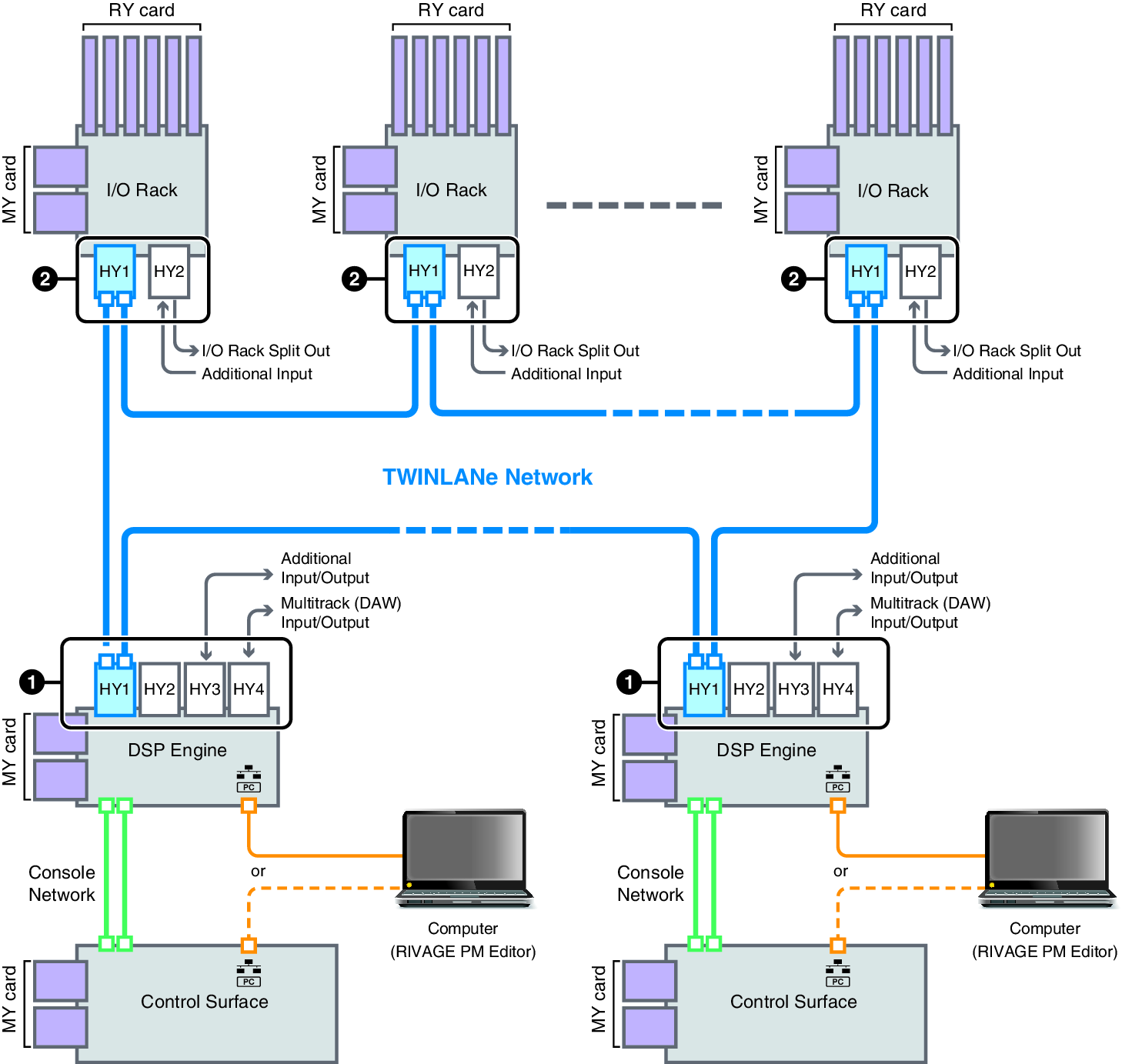
The diagram below shows typical connections for the RIVAGE PM series. Equipment can be combined in various ways to construct small systems or large systems.
• Connecting the control surface and DSP engine (Console Network)
A DSP engine has a dedicated connector (TO CONSOLE) for connection to the control surface. A network created by the control surface and a DSP engine is called a “Console Network.” The Console Network is connected as a ring. This provides redundancy for both audio signals and control signals.
• Connection between DSP engines and I/O racks (TWINLANe Network)
A DSP engine and an I/O rack are connected via a TWINLANe network, using HY card slot 1. The TWINLANe Network is connected as a ring. For each ring, a maximum of four (in a DSP mirroring configuration, a maximum of eight) DSP engines and a maximum of eight I/O racks can be connected.
About the HY card slots
a | Each HY card slot 1 – 4 is 256-in/out. A TWINLANe network card will work exclusively in HY card slot 1 or 2 on the DSP engine (or HY card slot 1 on the CSD-R7). The multitrack recording function will work exclusively in HY card slot 4 (or HY card slot 3 on the CSD-R7). |
b | HY card slot 1 of the I/O rack is only for a TWINLANe network card. HY card slot 2 is reserved for Dante/MADI/WSG-HY128. HY card slot 1 is 256-in/out, and HY card slot 2 is 128-in/out. |
| Ethernet connection Ethernet cable (CAT5 or better) (maximum 100 meters) |
| Console Network Ethernet cable (CAT5e or better) (maximum 100 meters) * etherCON connectors made by Neutrik are recommended. |
| TWINLANe Network Multi-mode optical fiber cable (maximum 300 meters between devices) Single-mode optical fiber cable (maximum 2km between devices) * LC Duplex connectors compatible with Neutrik’s opticalCON are recommended. |


System configuration example
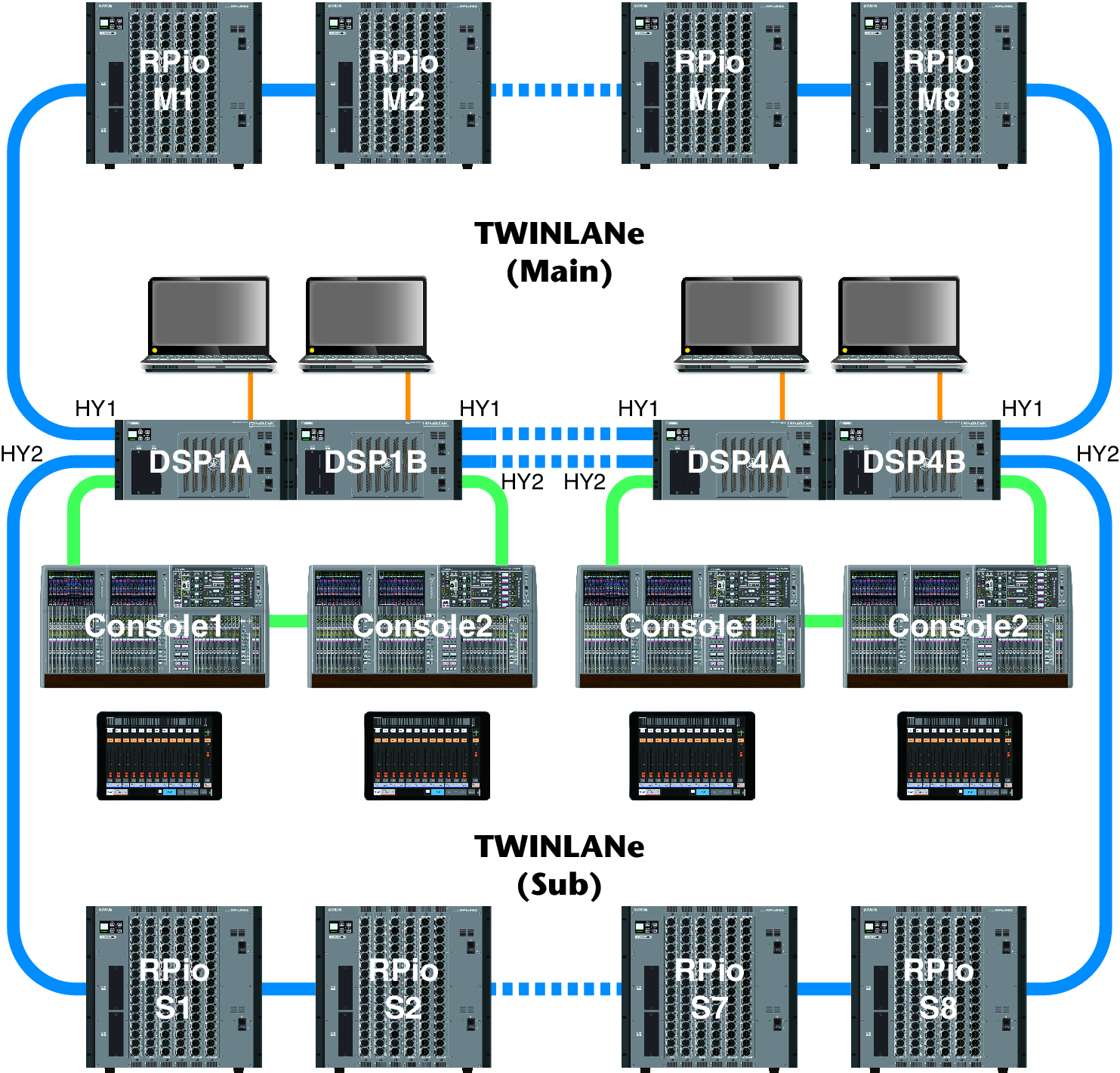
The ID settings of components are shown below.
CS-R10, CS-R10-S, CS-R5 Console ID | DSP-RX, DSP-RX-EX, DSP-R10 Unit ID | CSD-R7 Unit ID | CSD-R7 INTERNAL DSP ID | RPio Unit ID |
|---|---|---|---|---|
1, 2 | 1, 2, 3, 4 (In a DSP mirroring configuration, 1A/1B–4A/4B) | 1 | 1, 2, 3, 4 | M1, M2…M8 S1, S2…S8 |