

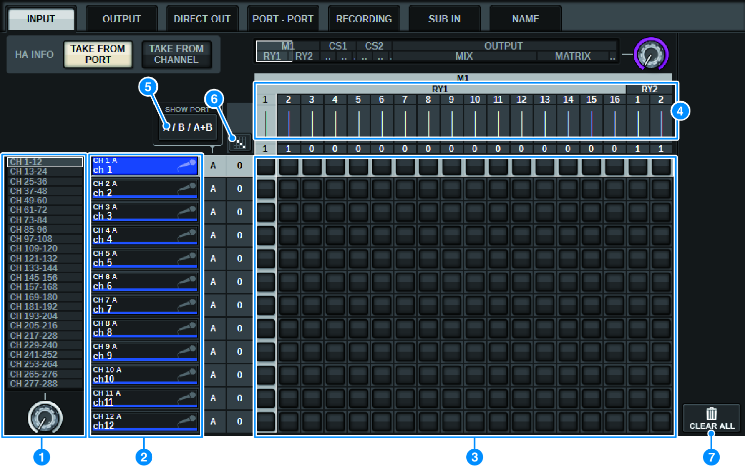
INPUT patch window
This screen contains the following items.
a | Channel list (Input channels) Indicates the input channel numbers as patching destinations. |
b | Channel display Indicates the channels that will be assigned to the input port. |
c | Grid This grid lets you patch input ports (horizontal lines) to input channels (vertical columns). Currently-patched grids are indicated by white squares. Press or click a desired grid to set or disable the patch. |
d | INPUT COMPONENT/SLOT/CH (input components/slots/channels) This section indicates the type of the input component, slot number, and channel number for the input port. The abbreviations displayed in this section have the following meaning.
NOTICE
|
e | SHOW PORT button Enables you to select the ports that are displayed in the grid from A, B, and A+B. |
f | Continuous Patch Press the continuous patch |
 button
  button and the
  button will appear. Press the
 g | CLEAR ALL button Press this button to clear all patches. |
h | HA INFO button When modifying an input patch, you can select whether the HA settings of the patched port will be used as-is (TAKE FROM PORT), or whether the HA settings of the channel will be copied to the patched port (TAKE FROM CHANNEL). When the TAKE FROM CHANNEL button is selected, the HA settings below will be copied from the channel side to the patched port. The default settings will be used when patching a (non-HA) input that does not have these settings to an input channel. HA settings and defaults HA gain (-6 dB) HPF ON/OFF (OFF) +48V ON/OFF (OFF) GC ON/OFF (OFF) φON/OFF (OFF) HPF frequency (80 Hz) SILK ON/OFF (OFF) SILK RED/BLUE (RED) SILK (0.0) M/S ON/OFF (OFF) M/S S-GAIN (STEREO) |