

Operating the METER screen
You can call up the METER screen (FULL SCREEN) to display the input/output levels for all channels onscreen, or to switch between meter points (the locations where level is detected) on the level meters.
Tabs
Use these tabs to switch between the INPUT METER, OUTPUT METER and DCA METER screens.

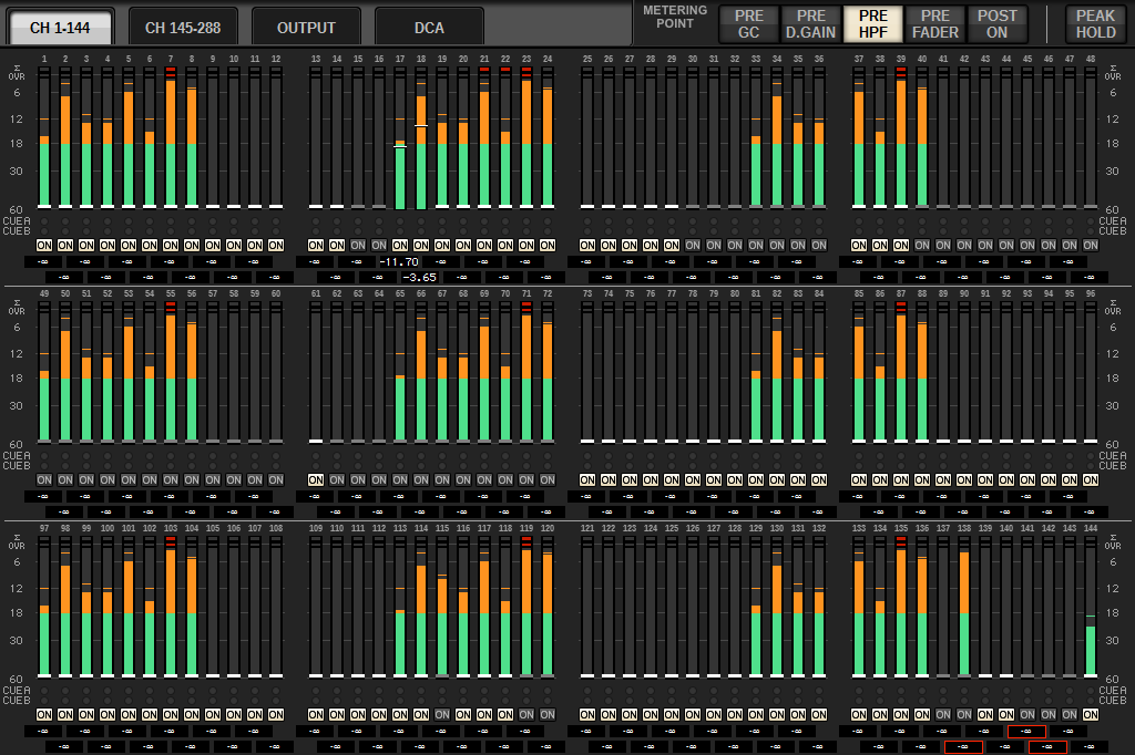
METER FULL SCREEN (INPUT) screen
This screen shows the input channel meters, faders and ON buttons.
METER FULL SCREEN (OUTPUT) screen
This screen shows the meters for all output channels, STEREO A/B, CUE A/B and MONITOR A/B.
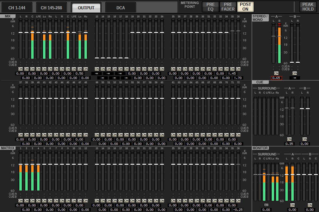
- When using Surround mode, SURROUND A/B will display instead of MIX1–12, SURROUND CUE will display to the left of CUE, and SURROUND MONITOR will display to the left of MONITOR.
METER FULL SCREEN (DCA) screen
This screen shows the meters for DCA, STEREO A/B, CUE A/B and MONITOR A/B.
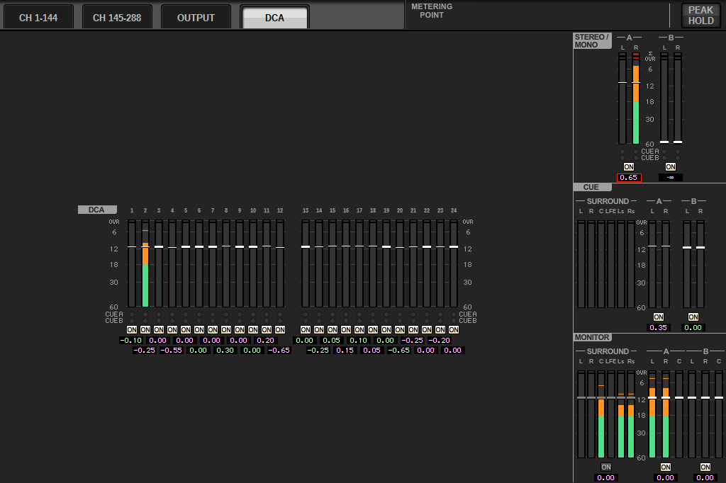
- When using Surround mode, SURROUND CUE will display to the left of CUE, and SURROUND MONITOR will display to the left of MONITOR.
Fader level/meter display
This screen shows the meters and faders for each channel.
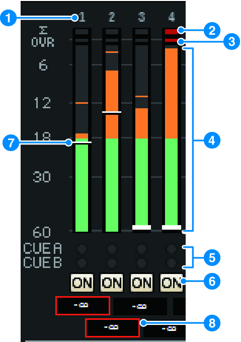
a | Channel number Indicates the channel number. |
b | ∑ clipping indicator This indicator lights when a signal is clipping at some point in the channel. |
c | OVER indicator Lights to indicate that a signal is clipping at the meter point in the channel. |
d | Meter Indicates the input or output level of the channel. Click this with your mouse to switch fader banks. |
e | CUE A/B indicators Shows the CUE status. |
f | ON indicators Indicates the channel on/off status. Click the indicators with your mouse to toggle them on/off. |
g | Fader Indicates the channel level as a fader position. When the channel’s [ON] key is turned OFF, the fader will turn gray. Drag with the mouse to adjust the level. Use CTRL+click to return to the default value, or CTRL+SHIFT+click to set the nominal value. |
h | Fader level/Channel name Indicates the channel level as a value (in dB). Click this with your mouse to toggle between fader level display and channel name display. The ISOLATE status is indicated by a red box. |
- Touch (or click) the 12-channel fader bank to recall the corresponding fader level on the panel.
METERING POINT field
Select one of the following meter points used for level detection. The meter points for level meters can be set separately for input and output channels.
■ For the INPUT METER
• PRE GC
• PRE D.GAIN
• PRE HPF
• PRE FADER
• POST ON

PRE CG is enabled when the device patched into the input features a GC. If the channel does not feature GC, the meter will indicate the PRE D.GAIN value at the PRE GC metering point.
■ For the OUTPUT METER
• PRE EQ
• PRE FADER
• POST ON

PEAK HOLD button
When this button is on, the peak level for each meter will be maintained. When the button is turned off, the peak levels will be cleared. Turning the PEAK HOLD button on/off will affect both the input and output channel. Turn the button off to clear the peak level indicator that was previously maintained.

- You can assign the function for toggling the PEAK HOLD button on/off to the USER DEFINED key.