

Rear Panel
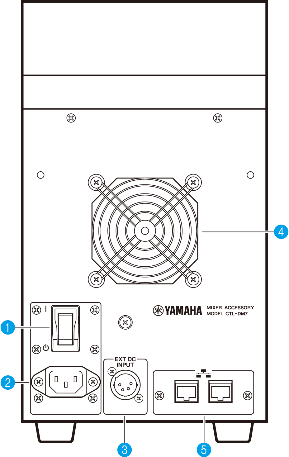
a | [ | ]/[ z] (Power switch) Toggles the power between on ( | ) and off (z). If the unit will not be used for a long time, be sure to remove the power cord from the AC outlet. When the switch is (z), the power is off. NOTICE
|
b | AC IN connector Use this socket to connect the supplied power cord. First connect the AC power cord to this unit, and then insert the power cord plug into an AC outlet. Insert the cord plug all the way until it locks in place securely. The supplied AC power cord features a V-lock latch mechanism, which prevents the power cord from disconnecting accidentally.
To disconnect a power cord, remove it while pressing the latch on the plug. |
 CAUTION
c | [EXT DC INPUT] This is an XLR 4-pin chassis connector that provides external power supply (DC 24 V) as a backup for the internal power supply of this product. For this connector, use the Yamaha PA-700 AC Adaptor or an equivalent item recommended by Yamaha. To connect the AC adaptor, first connect the AC adaptor cord to the AC adaptor, and then insert the DC plug into this connector. Finally, insert the power cord plug into an AC outlet.
|
d | Cooling vent This product is equipped with a cooling fan. This vent lets warm air escape from the unit. Make sure that you do not block the vent with any object. The air is taken in through the ventilation ports under the front.
|
e | Network connectors These RJ-45 connectors allow the unit to be connected to a computer via an Ethernet cable (CAT5e or higher recommended). In this way, you can control the unit externally from supported application software, such as DM7 Editor. Since the L2 switch is built in, you can set up this product to share and link functions with the DM7 console by connecting one of these connectors to the DM7 console and the other to a computer. These connectors do not support a redundant connection. NOTICE
|