Control Components
3. Control Components
3.1. Control Methods for Control Components
Control components can be divided into three broad types.
3.1.1. Trigger-type control components:
Trigger-type components are used primarily to output control signals through the operation of knobs, buttons, etc. and to use those signals to control other components, or to execute desired processes by sending control signals to processing-type components.
(It is also possible to move a controller by inputting a control signal.)
For trigger-type components, there are three types of controllers (Fader, Button, Radio Button) and two types of data types (Value, Normalized Value) for the control signal output for each (control signal input to the controlled component), for a total of six types of components.
The following example (Fader) explains how to use this list.
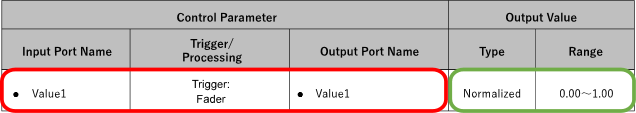
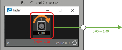
The fader control component can send continuous value control signals to the target component.
-
Control Parameter ( Red outline ):
The name of the port used to output the controller change notification (Output Port Name) and the controller parameter type (Trigger/Processing). In addition, the name of the input port used to externally control the controller (Input Port Name) is also listed. -
Output Value ( Green outline ):
Data type and range of output values that are output when the controller is operated.
(Example) Fader (Normalized)
3.1.2. Processing-type control components:
Processing-type components output the result of specific processing in response to an input control signal. The DME provides components for each of these process types.
The following example (NOT) explains how to use this list.
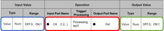
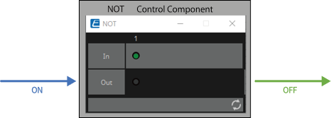
The NOT control component is a control component that inverts the input value (OFF:0, ON:1).
-
Control Parameter ( Red outline ):
The name of the port for input data for the Processing process (Input Port Name), the name of the port for notification of the result of the Processing process (Output Port Name), and the controller parameter type (Trigger/Processing). -
Input Value ( Blue outline ):
Recommended data types and ranges for Processing process input values. -
Output Value ( Green outline ):
Data type and range of the output value of the Processing process results.
(Example) NOT (Normalized Value)
3.1.3. Other:
Components of types other than the two described above (trigger type and processing type).
3.2. Input (Normalized Value): Button
Switching the Button’s on/off state causes output of the specified value (normalized value).
(For 2 inputs)
INPUT
On1: Input value to control the channel 1 button (OFF:0, ON:1)
On2: Input value to control the channel 2 button (OFF:0, ON:1)
OUTPUT
On1: Outputs the channel 1 setting value (0.00–1.00)
On2: Outputs the channel 2 setting value (0.00–1.00)
The button turns off when 0 is input from the input port, and turns on when 1 is input.
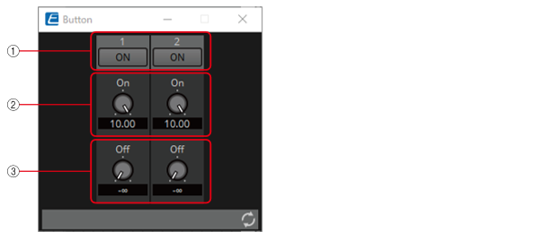
3.2.1. “Button” component editor

① When the button is switched on, the value set in ② is output, and when the button is switched off, the value set in ③ is output.
![]()
② 0.00–1.00
③ 0.00–1.00
Parameter types of the input/output values for each Port
|
Operation |
Output Value |
|||
|---|---|---|---|---|
|
Input Port Name |
Trigger/Processing |
Output Port Name |
Type |
Range |
|
● On1 |
Trigger: Button |
● On1 |
Normalized |
0.00–1.00 |
* It is also possible to control the ON button by inputting OFF:0 and ON:1 in the Value (Num) data type for the Input Port.
3.3. Input (Value): Button
Switching the button’s on/off state causes output of the specified value.
The type of output value (Num or dB) can be selected in the dialog that is displayed when the component is placed.
(For 2 inputs)
INPUT
On1: Input value to control the channel 1 button (OFF:0, ON:1)
On2: Input value to control the channel 2 button (OFF:0, ON:1)
OUTPUT
On1: Outputs the channel 1 setting value (–20,000 to 20,000), (−∞ to 10.00)
On2: Outputs the channel 2 setting value (–20,000 to 20,000), (−∞ to 10.00)
The button turns off when 0 is input from the input port, and turns on when 1 is input.
3.3.1. ”Button” component editor (Num)

① When the button is switched on, the value set in ② is output, and when the button is switched off, the value set in ③ is output.
![]()
② –20,000 to 20,000
③ –20,000 to 20,000
3.3.2. ”Button” component editor (dB)
① When the button is switched on, the value set in ② is output, and when the button is switched off, the value set in ③ is output.
![]()
② −∞ to 10.00
③ −∞ to 10.00
Parameter types of the input/output values for each Port
|
Operation |
Output Value |
||||
|---|---|---|---|---|---|
|
Input Port Name |
Trigger/Processing |
Output Port Name |
Type |
Range |
|
|
● On1 |
Trigger: Button |
● On1 |
Value |
dB |
−∞–10.00 |
|
Num |
-20000–20000 |
||||
* It is also possible to control the ON button by inputting OFF:0 and ON:1 in the Value (Num) data type for the Input Port.
3.4. Input (Normalized Value): Radio Button
Only one of multiple buttons can be turned on. All buttons can be turned off. When a button is switched to on, the channel number of the button that turned on and the specified value (normalized value) are output.
(For 2 inputs)
INPUT
1: Input value to control button 1 (OFF:0, ON:1)
2: Input value to control button 2 (OFF:0, ON:1)
Sel: Specifies the button number to turn on (*)
OUTPUT
1: Outputs 1 when button 1 is turned ON and 0 when button 1 is turned OFF.
2: Outputs 1 when button 2 is turned ON and 0 when button 2 is turned OFF.
Out: Outputs the set value of the location where the button has been turned ON.
Sel: Number of the button that has turned on (*)
* is displayed when the Parameters Control PINs are checked.
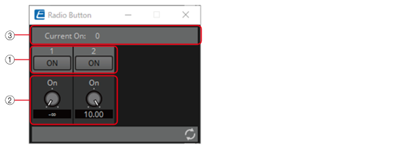
3.4.1. “Radio Button” component editor

① When the button is switched on, the value set in ② is output.
![]()
② 0.00–1.00
③ Displays the channel number for which the button has turned on. If all of them are off, "0" will be displayed.
Parameter types of the input/output values for each Port
|
Operation |
Output Value |
||||
|---|---|---|---|---|---|
|
Input Port Name |
Trigger/Processing |
Output Port Name |
Type |
Range |
|
|
● CH (1,2..) |
Trigger: Radio Button |
● CH (1,2..) |
Normalized |
OFF:0,
|
|
|
- |
● Out |
Value |
Num |
0.00–1.00 |
|
|
● Sel |
● Sel |
Value |
Num |
1–256 |
|
* Input Port: It is also possible to control the ON button by inputting OFF:0 and ON:1 in the Value (Num) data type for CH.
* Input Port: It is also possible to control the ON button by inputting the CH number in the Value (Num) data type for Sel.
3.5. Input (Value): Radio Button
Only one of multiple buttons can be turned on. All buttons can be turned off. When a button is switched to on, the channel number of the button that turned on and the specified value are output.
The type of output value (Num or dB) can be selected in the dialog that is displayed when the component is placed.
(For 2 inputs)
INPUT
1: Input value to control button 1 (OFF:0, ON:1)
2: Input value to control button 2 (OFF:0, ON:1)
Sel: Specifies the button number to turn on (*)
OUTPUT
1: Outputs 1 when button 1 is turned on and 0 when button 1 is turned off
2: Outputs 1 when button 2 is turned on and 0 when button 2 is turned off
Out: Outputs the set value of the location where the button has been turned on
Sel: Number of the button that has turned on (*)
* is displayed when the Parameters Control PINs are checked.
3.5.1. ”Radio Button” component editor (Num)

① When the button is switched on, the value set in ② is output.
![]()
② –20,000 to 20,000
③ Displays the channel number for which the button has turned on. If all of them are off, "0" will be displayed.
3.5.2. ”Radio Button” component editor (dB)
① When the button is switched on, the value set in ② is output.
![]()
② −∞ to 10 dB
③ Displays the channel number for which the button has turned on. If all of them are off, "0" will be displayed.
Parameter types of the input/output values for each Port
|
Operation |
Output Value |
||||
|---|---|---|---|---|---|
|
Input Port Name |
Trigger/Processing |
Output Port Name |
Type |
Range |
|
|
● CH (1,2..) |
Trigger: Radio Button |
● CH (1,2..) |
Value |
Num |
OFF:0 ON:1 |
|
- |
● Out |
Value |
dB |
−∞–10.00 |
|
|
Num |
-20000–20000 |
||||
|
● Sel |
● Sel |
Value |
Num |
1-256 |
|
* Input Port: It is also possible to control the ON button by inputting OFF:0 and ON:1 in the Value (Num) data type for CH.
* Input Port: It is also possible to control the ON button by inputting the CH number in the Value (Num) data type for Sel.
3.6. Input (Normalized Value): Fader
Continuous values (normalized values) are output by adjusting the controller.
(For 2 inputs)
INPUT
Value 1: Input value to control knob 1 (0.00–1.00)
Value 2: Input value to control knob 2 (0.00–1.00)
OUTPUT
Value 1: Output value when knob 1 is operated (0.00–1.00)
Value 2: Output value when knob 2 is operated (0.00–1.00)
The knob can also be controlled by an input signal (0.00–1.00).
3.6.1. ”Fader” component editor
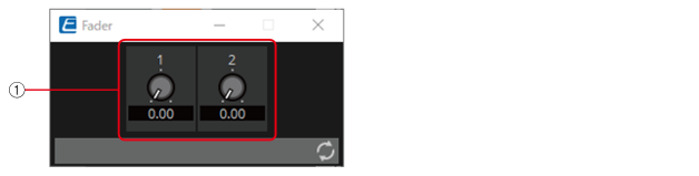
① Outputs a normalized value (0.00–1.00).
![]()
Parameter types of the input/output values for each Port
|
Operation |
Output Value |
|||
|---|---|---|---|---|
|
Input Port Name |
Trigger/Processing |
Output Port Name |
Type |
Range |
|
● Value1 |
Trigger: Fader |
● Value1 |
Normalized |
0.00–1.00 |
* It is also possible to control the controller by entering numerical values for Value (Num), Value (dB), and Normalized Value to the Input Port.
3.7. Input (Value): Fader
Continuous values are output by adjusting the controller.
The type of output value (Num or dB) can be selected in the dialog that is displayed when the component is placed.
(For 2 inputs)
INPUT
Value1: Input value to control knob 1 (–20,000 to 20,000), (−∞ to 10.00)
Value2: Input value to control knob 2 (–20,000 to 20,000), (−∞ to 10.00)
OUTPUT
Value1: Output value when knob 1 is operated (–20,000 to 20,000), (−∞ to 10.00)
Value2: Output value when knob 2 is operated (–20,000 to 20,000), (−∞ to 10.00)
The knob can also be controlled by an input signal (–20,000 to 20,000), (−∞ to 10.00).
3.7.1. ”Fader” component editor (Num)
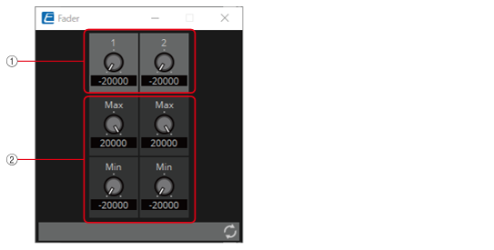
① Outputs a value of –20,000 to 20,000.
![]()
② MAX and MIN specify the fader operation range (–20,000 to 20,000).
3.7.2. ”Fader” component editor (dB)
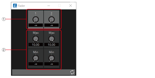
① Outputs a value of −∞ to 10.00.
![]()
② MAX and MIN specify the fader operation range (−∞ to 10.00).
Parameter types of the input/output values for each Port
|
Operation |
Output Value |
||||
|---|---|---|---|---|---|
|
Input Port Name |
Trigger/Processing |
Output Port Name |
Type |
Range |
|
|
● Value1 |
Trigger: Fader |
● Value1 |
Value |
Num |
-20000–20000 |
|
dB |
∞–10.00 |
||||
|
Num |
-20000–20000 |
||||
|
dB |
−∞–10.00 |
||||
* It is also possible to control the knob from ① by entering numerical values for Value (Num), Value (dB), and Normalized Value to the Input Port.
3.8. Processing (Normalized Value): Logic
This is the basic circuit component.
AND, NAND, OR, NOR, XOR, NOT XOR or 1 of N can be selected in the dialog that is displayed when the component is placed.
(For 2 inputs)
INPUT
1: Input value 1 to Logic (OFF:0, ON:1)
2: Input value 2 to Logic (OFF:0, ON:1)
OUTPUT
Out: Logic process results (OFF:0, ON:1)
3.8.1. ”Logic” component editor
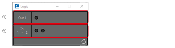
① Input signals can be checked.
② Output signals (process results) can be checked.
3.8.2. ”Logic” component editor (AND)
When all of the inputs are 1, then the output is 1.
If any 1 of the inputs is 0, then the output is 0.
If the input and output are 0, the indicator is off, and if the input and output are 1, the indicator is on.
3.8.3. ”Logic” component editor (NAND)
When all of the inputs are 1, then the output is 0.
If any 1 of the inputs is 0, then the output is 1.
If the input and output are 0, the indicator is off, and if the input and output are 1, the indicator is on.
3.8.4. ”Logic” component editor (OR)
When all of the inputs are 0, then the output is 0.
If any 1 of the inputs is 1, then the output is 1.
If the input and output are 0, the indicator is off, and if the input and output are 1, the indicator is on.
3.8.5. ”Logic” component editor (NOR)
When all of the inputs are 0, then the output is 1.
If any 1 of the inputs is 1, then the output is 0.
If the input and output are 0, the indicator is off, and if the input and output are 1, the indicator is on.
3.8.6. ”Logic” component editor (XOR)
When the number of 1 inputs is odd, the output is 1.
When the number of 1 inputs is even, the output is 0.
If the input and output are 0, the indicator is off, and if the input and output are 1, the indicator is on.
3.8.7. ”Logic” component editor (NOT XOR)
When the number of 1 inputs is even, the output is 1.
When the number of 1 inputs is odd, the output is 0.
If the input and output are 0, the indicator is off, and if the input and output are 1, the indicator is on.
3.8.8. ”Logic” component editor (1 of N)
If any 1 of the inputs is 1, then the output is 1.
If any 2 or more of the inputs are 1, then the output is 0.
If the input and output are 0, the indicator is off, and if the input and output are 1, the indicator is on.
Parameter types of the input/output values for each Port
|
Input Value |
Operation |
Output Value |
||||||
|---|---|---|---|---|---|---|---|---|
|
Type |
Range |
Input Port Name |
Trigger/Processing |
Output Port Name |
Type |
Range |
||
|
Value |
Num |
OFF:0,
|
● CH (1,2..) |
Processing: Logic (AND, NAND, OR, NOR, XOR, NOT XOR, 1 of N) |
● Out |
Value |
Num |
OFF:0,
|
3.9. Processing (Normalized Value): NOT
This component inverts the input value.

INPUT
1: Input value (OFF:0, ON:1)
OUTPUT
Out1: NOT process results (OFF:0, ON:1)
If the input value is 1, then the output is 0.
If the input value is 0, then the output is 1.
3.9.1. ”NOT” component editor
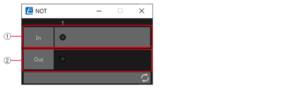
① On when the input value is 1, off when the input value is 0.
② On when the output value is 1, off when the output value is 0.
Parameter types of the input/output values for each Port
|
Input Value |
Operation |
Output Value |
||||||
|---|---|---|---|---|---|---|---|---|
|
Type |
Range |
Input Port Name |
Trigger/Processing |
Output Port Name |
Type |
Range |
||
|
Value |
Num |
OFF:0,
|
● CH (1,2..) |
Processing: NOT |
● Out |
Value |
Num |
OFF:0,
|
3.10. Processing (Normalized Value): Flip-Flop
This component is used to enable toggle operation.
INPUT
Set: Trigger input to push the [Set] button*
Reset: Trigger input to push the [Reset] button*
Toggle: Trigger input to push the [Toggle] button*
*: Values that are input from an external source act as simple triggers that are not related to any operation.
OUTPUT
Out: on/off state of the [Set] button (OFF:0, ON:1)
Not Out: Out inversion value
When the [Set] button is on, 1 is output from Out, and the Out inversion value is output from Not Out.
When the [Reset] button is turned on, the [Set] button is turned off.
3.10.1. ”Flip-Flop” component editor
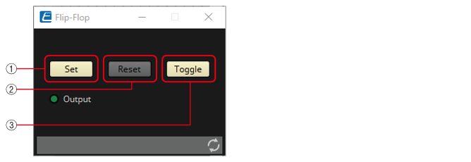
① When the [Set] button is turned on, the [Toggle] button also turns on, and the [Output] indicator turns on.
② When the [Reset] button is turned on, the [Toggle] button turns off, and the [Output] indicator turns off. 0 is output from Out, and 1 is output from Not Out.
③ When the [Toggle] button is pressed, it switches between on or off. When it is on, the [Set] button runs the on process, and when it is off, the [Reset] button runs the on process.
Parameter types of the input/output values for each Port
|
Input Value |
Operation |
Output Value |
||||||
|---|---|---|---|---|---|---|---|---|
|
Type |
Range |
Input Port Name |
Trigger/Processing |
Output Port Name |
Type |
Range |
||
|
Trigger Input |
- |
● Set |
Processing: Flip-Flop |
- |
- |
- |
- |
|
|
Trigger Input |
- |
● Reset |
- |
- |
- |
- |
||
|
Trigger Input |
- |
● Toggle |
- |
- |
- |
- |
||
|
- |
- |
- |
- |
● Out |
Value |
Num |
OFF:0,
|
|
|
- |
- |
- |
- |
● NotOut |
Value |
Num |
OFF:0,
|
|
3.11. Processing (Normalized Value): Invert
This component calculates the maximum value of the normalized value (1.00) minus the input value.

(For 2 inputs)
INPUT
1: Channel 1 input value (0.00–1.00)
2: Channel 2 input value (0.00–1.00)
OUTPUT
Out1: 1.00 minus the channel 1 input value
Out2: 1.00 minus the channel 2 input value
3.11.1. ”Invert” component editor
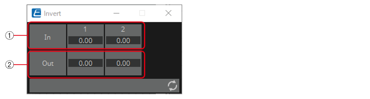
① The input value (0.00–1.00) can be checked.
② 1.00 minus the input value ① is output as the value.
Parameter types of the input/output values for each Port
|
Input Value |
Operation |
Output Value |
||||
|---|---|---|---|---|---|---|
|
Type |
Range |
Input Port Name |
Trigger/Processing |
Output Port Name |
Type |
Range |
|
Normalized |
0.00–1.00 |
● CH (1,2..) |
Processing: Invert |
● CH (1,2..) |
Normalized |
0.00–1.00 |
3.12. Processing (Normalized Value): Compare
This component is used to obtain the result of comparing two input values.
Greater, Less or Equal can be selected in the dialog that is displayed when the component is placed.
INPUT
1: Input value 1 (0.00–1.00)
2: Input value 2 (0.00–1.00)
OUTPUT
Out: Comparison result (0, 1)
3.12.1. ”Compare” component editor
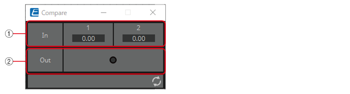
① Input values can be checked. (0.00–1.00)
② Outputs the result of comparing two input values.
3.12.2. ”Compare” component editor (Greater)
When In1 > In2, 1 is output, and the Out indicator turns on.
For all other cases, 0 is output and the indicator turns off.
3.12.3. ”Compare” component editor (Less)
When In1 < In2, 1 is output, and the Out indicator turns on.
For all other cases, 0 is output and the indicator turns off.
3.12.4. ”Compare” component editor (Equal)
When In1 = In2, 1 is output, and the Out indicator turns on.
For all other cases, 0 is output and the indicator turns off.
Parameter types of the input/output values for each Port
|
Input Value |
Operation |
Output Value |
||||||
|---|---|---|---|---|---|---|---|---|
|
Type |
Range |
Input Port Name |
Trigger/Processing |
Output Port Name |
Type |
Range |
||
|
Normalized |
0.00–1.00 |
● CH (1,2) |
Processing: Compare (Greater, Less, Equal) |
- |
- |
- |
- |
|
|
- |
- |
- |
- |
● Out |
Value |
Num |
OFF:0,
|
|
3.13. Processing (Normalized Value): Difference
This component is used to obtain the difference between two input values.

INPUT
1: Input value 1 (0.00–1.00)
2: Input value 2 (0.00–1.00)
OUTPUT
Out: The value of input 1 minus input 2
If the result of subtracting input value 2 from input value 1 is negative (minus), the result is 0.00.
3.13.1. ”Difference” component editor
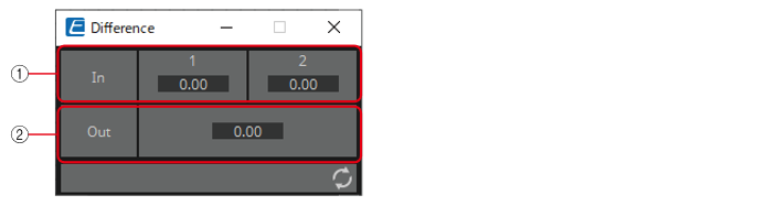
① The input value (0.00–1.00) can be checked.
② Displays the value of subtracting input value 2 from input value 1.
Parameter types of the input/output values for each Port
|
Input Value |
Operation |
Output Value |
||||||
|---|---|---|---|---|---|---|---|---|
|
Type |
Range |
Input Port Name |
Trigger/Processing |
Output Port Name |
Type |
Range |
||
|
Normalized |
0.00–1.00 |
● CH (1,2) |
Processing: Difference |
- |
- |
- |
- |
|
|
- |
- |
- |
- |
● Out |
Normalized |
0.00–1.00 |
||
3.14. Processing (Normalized Value): Max/Min
This component detects and outputs the largest/smallest value of the values input from multiple ports.

(For 2 inputs)
INPUT
1: Input value 1 (0.00–1.00)
2: Input value 2 (0.00–1.00)
OUTPUT
Max: The largest value from multiple input values (0.00–1.00)
Min: The smallest value from multiple input values (0.00–1.00)
3.14.1. ”Max/Min” component editor
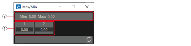
① The input value (0.00–1.00) can be checked.
② The largest value (0.00 to 1.00) among all channel inputs is displayed as Max and output from the Max port. The smallest value (0.00 to 1.00) among all channel inputs is displayed as Min and output from the Min port.
Parameter types of the input/output values for each Port
|
Input Value |
Operation |
Output Value |
||||||
|---|---|---|---|---|---|---|---|---|
|
Type |
Range |
Input Port Name |
Trigger/Processing |
Output Port Name |
Type |
Range |
||
|
Normalized |
0.00–1.00 |
● CH (1,2..) |
Processing: Max/Min |
- |
- |
- |
- |
|
|
- |
- |
- |
- |
● Max |
Normalized |
0.00–1.00 |
||
|
- |
- |
- |
- |
● Min |
Normalized |
0.00–1.00 |
||
3.15. Processing (Value): Negate
This component performs arithmetic operations on input values.
Negate, Square, Square Root or Absolute can be selected in the dialog that is displayed when the component is placed.

(For 2 inputs)
INPUT
1: Channel 1 input value (–20,000 to 20,000), (−∞ to 10.00)
2: Channel 2 input value (–20,000 to 20,000), (−∞ to 10.00)
OUTPUT
1: Calculation results for channel 1 input values
2: Calculation results for channel 2 input values
3.15.1. ”Negate” component editor

① Input signals can be checked.
② Output signals (process results) can be checked.
3.15.2. ”Negate” component editor (Negate)
Outputs the inverted positive/negative value of the input value.
3.15.3. “Negate” component editor (Square)
Outputs the square of the input value.
3.15.4. “Negate” component editor (Square Root)
Outputs the square root of the input value.
3.15.5. “Negate” component editor (Absolute)
Outputs the absolute value of the input value.
Parameter types of the input/output values for each Port
|
Input Value |
Operation |
Output Value |
|||||
|---|---|---|---|---|---|---|---|
|
Type |
Range |
Input Port Name |
Trigger/Processing |
Output Port Name |
Type |
Range |
|
|
Value |
Num |
-20000–20000 |
● CH (1,2..) |
Processing : Negate, Square, Square Root, Absolute |
● CH (1,2..) |
Actual Value |
|
|
dB |
−∞–10.00 |
||||||
3.16. Processing (Value): Compare
This component is used to obtain the result of comparing two input values.
Greater, Less or Equal can be selected in the dialog that is displayed when the component is placed.

INPUT
1: Input value 1 (–20,000 to 20,000), (−∞ to 10.00)
2: Input value 2 (–20,000 to 20,000), (−∞ to 10.00)
OUTPUT
Out: Comparison result (0, 1)
3.16.1. ”Compare” component editor

① Input values can be checked.
② Outputs the result of comparing two input values.
3.16.2. ”Compare” component editor (Greater)
When In1 > In2, 1 is output, and the Out indicator turns on.
For all other cases, 0 is output and the indicator turns off.
3.16.3. ”Compare” component editor (Less)
When In1 < In2, 1 is output, and the Out indicator turns on.
For all other cases, 0 is output and the indicator turns off.
3.16.4. ”Compare” component editor (Equal)
When In1 = In2, 1 is output, and the Out indicator turns on.
For all other cases, 0 is output and the indicator turns off.
Parameter types of the input/output values for each Port
|
Input Value |
Operation |
Output Value |
||||||
|---|---|---|---|---|---|---|---|---|
|
Type |
Range |
Input Port Name |
Trigger/Processing |
Output Port Name |
Type |
Range |
||
|
Value |
Num |
-20000–20000 |
● CH (1,2..) |
Processing: Compare (Greater, Less, Equal) |
- |
- |
- |
- |
|
dB |
−∞–10.00 |
- |
- |
- |
- |
|||
|
- |
- |
- |
- |
● Out |
Value |
Num |
OFF:0,
|
|
3.17. Processing (Value): Multi Compare
This component compares the input values from multiple ports and detects the channel number with the largest/smallest input value.
Greatest or Smallest can be selected in the dialog that is displayed when the component is placed.
(For 2 inputs)
INPUT
1: Input value 1 (–20,000 to 20,000), (−∞ to 10.00)
2: Input value 2 (–20,000 to 20,000), (−∞ to 10.00)
OUTPUT
Out 1: Outputs ON:1 when the channel 1 input value is the largest/smallest value. Outputs 0 for all other cases.
Out 2: Outputs ON:1 when the channel 2 input value is the largest/smallest value. Outputs 0 for all other cases.
3.17.1. “Multi Compare” component editor
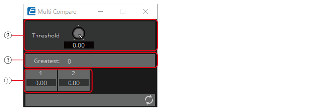
① Input signals can be checked.
② Threshold value
③ Displays the result (channels with the largest/smallest input values) of comparing multiple input values that exceed the Threshold value.
3.17.2. “Multi Compare” component editor (Greatest)
Compares input values greater than the Threshold value and outputs 1 from the channel determined to have the largest value. All other channels output 0.
3.17.3. “Multi Compare” component editor (Smallest)
Compares input values smaller than the Threshold value and outputs 1 from the channel determined to have the smallest value. All other channels output 0.
Parameter types of the input/output values for each Port
|
Input Value |
Operation |
Output Value |
||||||
|---|---|---|---|---|---|---|---|---|
|
Type |
Range |
Input Port Name |
Trigger/Processing |
Output Port Name |
Type |
Range |
||
|
Value |
Num |
-20000–20000 |
● CH (1,2..) |
Processing : Multi Compare ( Greatest, Smallest ) |
● CH (1,2..) |
Value |
Num |
OFF:0,
|
|
dB |
−∞–10.00 |
|||||||
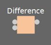
3.18. Processing (Value): Difference
This component is used to obtain the difference between two input values.
INPUT
1: Input value 1 (–20,000 to 20,000), (−∞ to 10.00)
2: Input value 2 (–20,000 to 20,000), (−∞ to 10.00)
OUTPUT
Out: The value of input 1 minus input 2
If the result of subtracting input value 2 from input value 1 is negative (minus), the result is 0.00.
3.18.1. “Difference” component editor
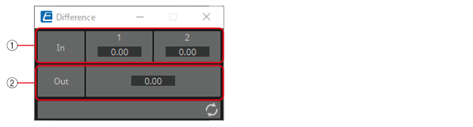
① Input signals can be checked.
② Displays the value of subtracting input value 2 from input value 1.
Parameter types of the input/output values for each Port
|
Input Value |
Operation |
Output Value |
||||||
|---|---|---|---|---|---|---|---|---|
|
Type |
Range |
Input Port Name |
Trigger/Processing |
Output Port Name |
Type |
Range |
||
|
Value |
Num |
-20000–20000 |
● CH (1,2) |
Processing: Difference |
- |
- |
- |
- |
|
dB |
−∞–10.00 |
- |
- |
- |
- |
|||
|
- |
- |
- |
- |
● Out |
Value |
Num |
-20000–20000 |
|
|
- |
- |
- |
- |
dB |
−∞–10.00 |
|||
3.19. Processing (Value): Max/Min
This component detects and outputs the largest/smallest value of the values input from multiple ports.
(For 2 inputs)
INPUT
1: Input value 1 (–20,000 to 20,000), (−∞ to 10.00)
2: Input value 2 (–20,000 to 20,000), (−∞ to 10.00)
OUTPUT
Max: The largest value from multiple input values
Min: The smallest value from multiple input values
3.19.1. ”Max/Min” component editor

① The input value (0.00–1.00) can be checked.
② The largest value among all channel inputs is displayed as Max and output from the Max port.
The smallest value among all channel inputs is displayed as Min and output from the Min port.
Parameter types of the input/output values for each Port
|
Input Value |
Operation |
Output Value |
||||||
|---|---|---|---|---|---|---|---|---|
|
Type |
Range |
Input Port Name |
Trigger/Processing |
Output Port Name |
Type |
Range |
||
|
Value |
Num |
-20000–20000 |
● CH (1,2..) |
Processing: Max/Min |
- |
- |
- |
- |
|
dB |
−∞–10.00 |
- |
- |
- |
- |
|||
|
- |
- |
- |
- |
● Max |
Value |
Num |
OFF:0,
|
|
|
dB |
−∞–10.00 |
|||||||
|
- |
- |
- |
- |
● Min |
Value |
Num |
OFF:0,
|
|
|
dB |
−∞–10.00 |
|||||||
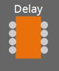
3.20. Processing: Delay
This component can delay the input signal before outputting it.
(For 2 inputs)
INPUT
1: Channel 1 input value
2: Channel 2 input value
On1: Input value to control the channel 1 button (OFF:0, ON:1) (*)
On2: Input value to control the channel 2 button (OFF:0, ON:1) (*)
OUTPUT
1: Channel 1 input value
2: Channel 2 input value
On 1: Output value when the channel 1 button is switched (OFF:0, ON:1) (*)
On 2: Output value when the channel 2 button is switched (OFF:0, ON:1) (*)
* is displayed when the Parameters Control PINs are checked.
If the delay time is 0 msec, the input signal is output through without change.
3.20.1. “Delay” component editor
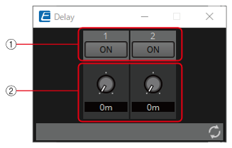
① Switches the enable/disable for the Delay function.
![]()
② When any value is input to the channel input, that input value is then output with a delay of the specified delay time (0 ms to 60.00 s).
It can be delayed only when in the ON state.
Parameter types of the input/output values for each Port
|
Input Value |
Operation |
Output Value |
||||||
|---|---|---|---|---|---|---|---|---|
|
Type |
Range |
Input Port Name |
Trigger/Processing |
Output Port Name |
Type |
Range |
||
|
Through |
● CH (1,2..) |
Processing: Delay |
● CH (1,2..) |
Same value as the Input Value |
||||
|
Value |
Num |
OFF:0,
|
● ON (1,2..) |
● ON (1,2..) |
Value |
Num |
OFF:0,
|
|
3.21. Processing: External Events
Configures the command to send to the network using the input of 0 or 1 to an input port as a trigger.
One External event can be set for 1 input port.
A maximum of 16 External events can be set within a component.
The protocol (TCP, UDP) can be selected in the dialog that is displayed when the component is placed.
3.21.1. ”External Events” component editor
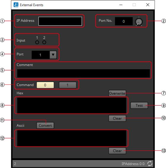
①
[IP Address] text box
Sets the IP address for the device that will receive the command.
②
[Port No.] text box/knob
Sets the port number for the device that will receive the command.
③
[Input] indicator
Displays the status of the signals input to each input port. The indicator turns off when "0" is input, and turns on when "1" is input.
④
[Port] list box
Selects the target for editing.
⑤
[Comment] text box
Allows for input of text. For example, it can be used to enter a description of an event to make it easier to identify.
⑥
Newline Code [CR(0D)]/[LF(0A)]/[CR+LF] button
Select a newline code to be inserted when a newline is added by "Add a newline code at the end of ‘Hex’." in [Hex] or a newline is started while [Ascii] editing is being performed.
CR is 0x0D, LF is 0x0A, and CR+LF is 0x0D 0x0A.
⑦
[Command] button
When 0 is selected, the command that will be sent when 0 is input to the input port will be edited in the [Hex] text box.
When 1 is selected, the command that will be sent when 1 is input to the input port will be edited in the [Hex] text box.
⑧
[Overwrite] button
When this has been set to on, the [Hex] text box is overwritten. Turn off to insert.
⑨
[Hex] text box
The command can be entered in hexadecimal.
⑩
Add a newline code at the end of ‘Hex’. [Add] button
Adds a newline code to the end of the displayed command.
⑪
D/C(Disconnection Delay) Time knob(TCP command only)
Sets the time to wait before the session with the connected device is disconnected after a command is sent.
Adjust this setting when you have difficulty in controlling your device.
⑫
[Test] button
The command entered in the [Hex] text box is sent directly from ProVisionaire Design.
⑬
[Hex] Clear button
Deletes the contents of the [Hex] text box.
⑭
[Convert] button
Converts the text string command entered in the [Ascii] text box into hexadecimal, and reflects it in the [Hex] text box.
⑮
[Ascii] text box
The command can be entered as a text string.
⑯
[Ascii] Clear button
Deletes the contents of the [Ascii] text box.
3.22. Processing: Hold Buffer
This component temporarily pauses the output of an input signal and holds the last input signal. When the hold is released, the last input signal will be output.
(For 2 inputs)
INPUT
1:Channel 1 input value(*)
2:Channel 2 input value(*)
On:Input value to control the ON button(OFF:0, ON:1)
* Basically, 1 only
OUTPUT
1:Channel 1 input value(*)
2:Channel 2 input value(*)
On:Output value when the ON button is toggled(OFF:0, ON:1)
* Basically, 1 only
3.22.1. Examples of Use
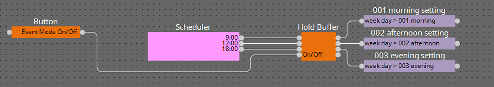
Use this Hold Buffer component to temporarily pause events registered in the scheduler. Setting Hold to On temporarily pauses the output, and setting it to Off outputs only the last input trigger.
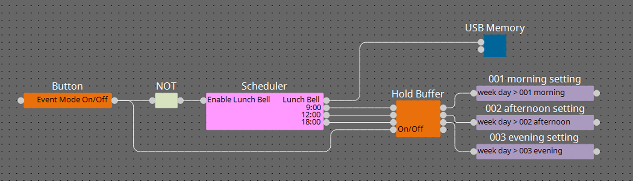
For events that you want to temporarily pause but do not need to resume, such as a scheduled bell, stop the event using the Enable/Disable function of the Scheduler component.
As shown in the image above, by setting up the logic, a single button can simultaneously handle two operations: stopping/immediately executing events that resume upon restart, such as time-based settings (Hold Buffer On/Off), and disabling/enabling events that should not resume upon restart, such as scheduled bells (Scheduler Disable/Enable).
3.22.2. “Hold Buffer” component editor
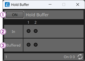
①When turned on, the output of signals will be stopped. When turned off, the last input signal (the signal from the channel that is lit in Buffered mode) will be emitted.
![]()
②All signals that were input during the pause will light up.
③The last signal that was input and held during the pause will light up.
Parameter types of the input/output values for each Port
|
Input Value |
Operation |
Output Value |
||||||
|---|---|---|---|---|---|---|---|---|
|
Type |
Range |
Input Port Name |
Trigger/Processing |
Output Port Name |
Type |
Range |
||
|
Through |
● CH (1,2..) |
Processing: Hold Buffer |
● CH (1,2..) |
Same value as the Input Value |
||||
|
Value |
Num |
OFF:0
|
● On |
● On |
Value |
Num |
OFF:0
|
|
3.23. Processing: Suspend
This is a control component to temporarily stop the output of the input signal.
(For 2 inputs)
INPUT
1: Channel 1 input value
2: Channel 2 input value
On1: Input value to control the channel 1 button (OFF:0, ON:1) (*)
On2: Input value to control the channel 2 button (OFF:0, ON:1) (*)
OUTPUT
1: Channel 1 input value
2: Channel 2 input value
On 1: Output value when the channel 1 button is switched (OFF:0, ON:1) (*)
On 2: Output value when the channel 2 button is switched (OFF:0, ON:1) (*)
* is displayed when the Parameters Control PINs are checked.
3.23.1. “Suspend” component editor
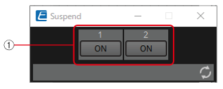
① When this is ON, the signal output is stopped.
![]()
Parameter types of the input/output values for each Port
|
Input Value |
Operation |
Output Value |
||||||
|---|---|---|---|---|---|---|---|---|
|
Type |
Range |
Input Port Name |
Trigger/Processing |
Output Port Name |
Type |
Range |
||
|
Through |
● CH (1,2..) |
Processing: Suspend |
● CH (1,2..) |
Same value as the Input Value |
||||
|
Value |
Num |
OFF:0,
|
● On (1,2..) |
● On (1,2..) |
Value |
Num |
OFF:0,
|
|
3.24. Processing: Router
Assigns an input to an output port.
One input can be output to multiple channels, but multiple inputs cannot be output to a single channel.
(For 2 inputs)
INPUT
1: Input value to channel 1
2: Input value to channel 2
Out1 In1: Switches the output of In1 to Out1 (OFF:0, ON:1) (*)
Out1 In2: Switches the output of In2 to Out1 (OFF:0, ON:1) (*)
Out1 Sel: Specifies the input signal output to Out1 (0–64) (*)
The signal is not output if 0 is specified.
Out2 In1: Switches the output of In1 to Out2 (OFF:0, ON:1) (*)
Out2 In2: Switches the output of In2 to Out2 (OFF:0, ON:1) (*)
Out2 Sel: Specifies the input signal output to Out2 (0–64) (*)
The signal is not output if 0 is specified.
OUTPUT
1: Output value from channel 1
2: Output value from channel 2
Out1 In1: Output state of In1 for Out1 (OFF:0, ON:1) (*)
Out1 In2: Output state of In2 for Out1 (OFF:0, ON:1) (*)
Out1 Sel: Specifies the input signal output to Out1 (0–64) (*)
Out2 In1: Output state of In1 for Out2 (OFF:0, ON:1) (*)
Out2 In2: Output state of In2 for Out2 (OFF:0, ON:1) (*)
Out2 Sel: Specifies the input signal output to Out2 (0–64) (*)
* is displayed when the Parameters Control PINs are checked.
3.24.1. ”Router” component editor
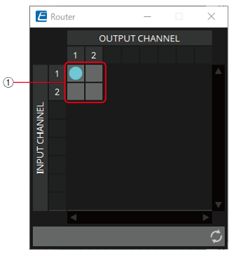
① This is the router that distributes inputs signals. Clicking on a square toggles the output on or off.
![]()
Parameter types of the input/output values for each Port
|
Input Value |
Operation |
Output Value |
||||||
|---|---|---|---|---|---|---|---|---|
|
Type |
Range |
Input Port Name |
Trigger/Processing |
Output Port Name |
Type |
Range |
||
|
Through |
● CH (1,2..) |
Processing: Router |
● CH (1,2..) |
Same value as Input Value |
||||
|
Value |
Num |
OFF:0,
|
● OUT (1,2..) (In1,2..) |
● OUT (1,2..) (In1,2..) |
Value |
Num |
OFF:0,
|
|
|
Value |
Num |
INPUT CH No |
● OUT (1,2..) Sel |
● OUT (1,2..) Sel |
Value |
Num |
INPUT CH No |
|
3.25. Controller: GPI In
Converts signals input from GPI IN into control signals that can be handled by the Control layer.
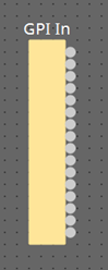
For the input from each GPI In connector (16 connectors), a continuous value (normalized from 0 to 1) is output from each output port.
There are two GPI Input setting methods.
-
Configure the settings in the GPI Input dialog that opens from the [Tools] button on the device sheet.
Try this method to execute a single function using the input from a single [GPI IN] connector. -
Add the GPI Input component to the Control layer of the device sheet and set it using in the Component Editor.
Try this method if you want to control multiple parameters/functions simultaneously by input from a single [GPI IN] connector, or if you want to combine control components to create complex operations.
* GPI Input is configured simultaneously by dialog setting and by the GPI Input component of the Control layer.
3.25.1. ”GPI Input” component editor
The input GPI signal is converted to a normalized value (0 to 1) using the specified method, and is then output.
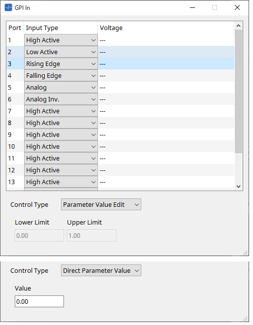
Refer to the GPI Input dialog in the ProVisionaire Design User Guide for the rest.
Parameter types of the input/output values for each Port
|
Input Value |
Operation |
Output Value |
|||||
|---|---|---|---|---|---|---|---|
|
Type |
Range |
Input Port Name |
Trigger/Processing |
Output Port Name |
Type |
Range |
|
|
- |
- |
- |
- |
Trigger: GPI IN |
● CH (1,2..) |
Normalized |
0.00–1.00 |
3.26. Controller: GPI Out
Outputs the GPI Out signal from the GPI Out connector.
There are two GPI Output setting methods.
-
Configure the settings in the GPI Output dialog that opens from the [Tools] button on the device sheet.
Try this method if you are using one operation as a trigger and outputting from a single [GPI OUT] connector. -
Add the GPI Output component to the Control layer of the device sheet and set it using in the Component Editor.
Try this method if you want to use multiple operations as a trigger and want to output them from a single [GPI OUT] connector, or if you want to combine control components to create complex operations.
* The output port type settings are linked in the dialog and the GPI Output component of the Control layer.
3.26.1. ”GPI Output” component editor
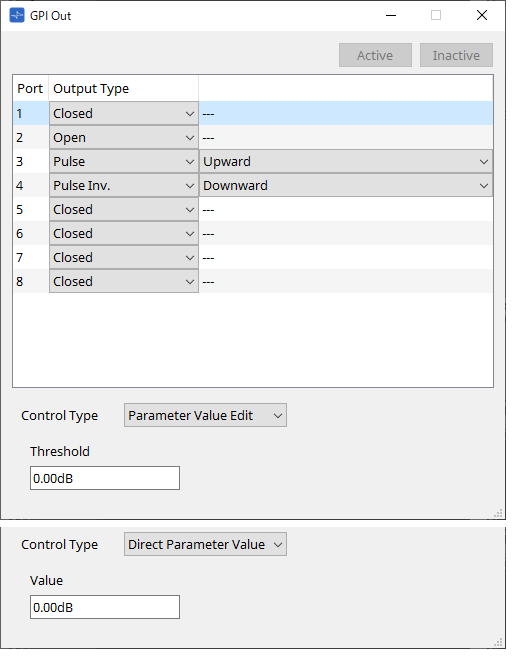
Refer to the GPI Input dialog in the ProVisionaire Design User Guide for the rest.
Parameter types of the input/output values for each Port
|
Input Value |
Operation |
Output Value |
|||||
|---|---|---|---|---|---|---|---|
|
Type |
Range |
Input Port Name |
Trigger/Processing |
Output Port Name |
Type |
Range |
|
|
Value |
Num |
OFF:0,
|
● CH (1,2..) |
Trigger: GPI OUT |
- |
- |
- |
3.27. Controller: Scheduler
Outputs a trigger at the time the event is activated.
INPUT
Enable 001: Controls the event’s ”Enable” parameter (OFF:0, ON:1).
OUTPUT
Event 001: Outputs 1 at the time the event activates
3.27.1. “Scheduler” component editor
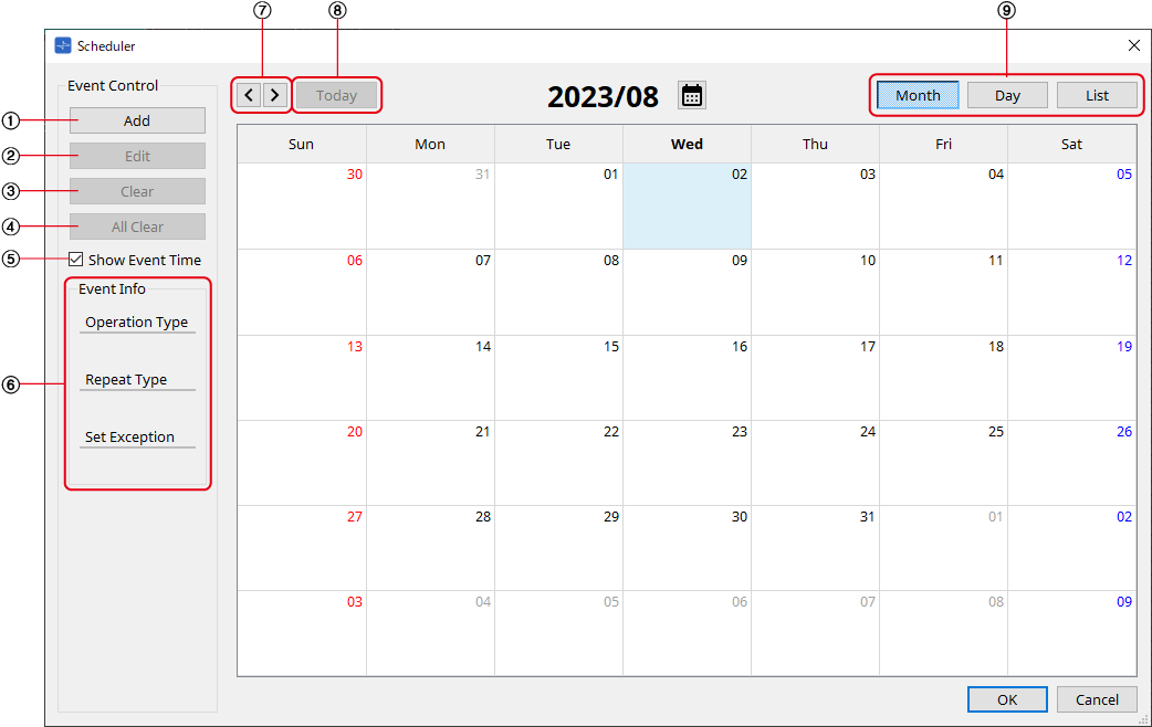
①
[Add] button
Opens the “Add Event” dialog.
②
[Edit] button
Opens the selected event’s edit dialog. See the Add Event dialog for a description of the setting items.
③
[Clear] button
Deletes the settings for the currently-selected event.
④
[All Clear] button
Deletes all events.
⑤
[Show Event Tim] check box
When this check box is empty (off), the event occurrence time is not displayed. This is to save display space.
⑥
Event Info
Displays a summary of the currently selected event.
⑦
[<][>] buttons
For Month, this advances/returns the display by one month.
For Day, this advances/returns the display by one day.
⑧
[Today] button
In Month view, this jumps to the month that includes today.
For the Day view, this display today’s schedule.
⑨
[Month]/[Day]/[List] selection button
Switches the calendar to month view/day view or event list view.
-
Month/Day
In the calendar, double-click the date you want; the “Add Event” dialog box will appear.
Events other than periodic events can be moved by dragging and dropping. -
List
Displays events linked to output terminals in numerical order of the terminal numbers.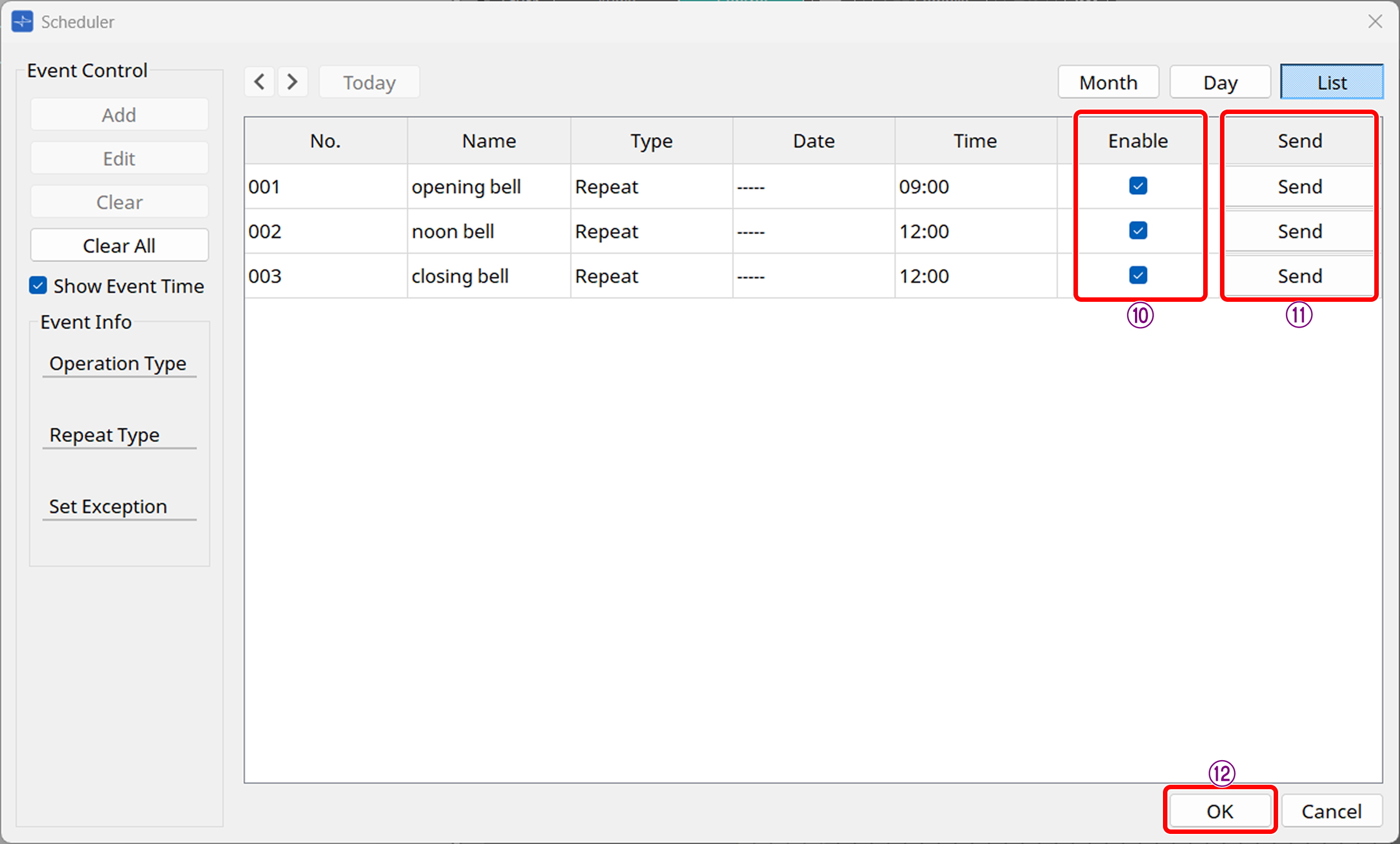
-
⑩[Enable] check box
Events can be enabled or disabled using the Enable checkbox. Additionally, this parameter can be assigned to each function. -
⑪[Send] button
Clicking this immediately executes the event. Clicking the [OK] button to confirm the event enables the [Send] button.
-
⑫
[OK] button
Clicking this confirms the event and closes the screen.
Parameter types of the input/output values for each Port
|
Input Value |
Operation |
Output Value |
|||||
|---|---|---|---|---|---|---|---|
|
Type |
Range |
Input Port Name |
Trigger/Processing |
Output Port Name |
Type |
Range |
|
|
Value |
Num |
OFF:0,
|
● Enable (001–100) |
- |
- |
- |
- |
|
- |
- |
- |
- |
- |
● Event (001, 002…) |
- |
1 |
3.27.2. “Add Event” dialog box
You can add an event here.
One-time events or recurring events can be configured.
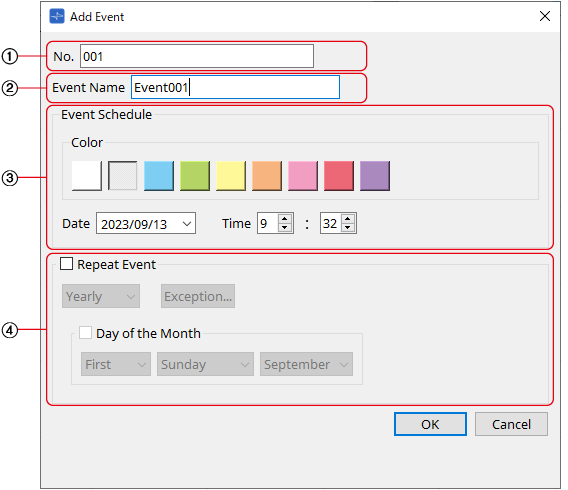
①
[No.] text box
Specifies the output terminal of the component issuing the event.
This can be changed after setting.
②
[Event Name] text box
Shows or edits the event name.
③ Event Schedule
-
[Color] selection button
Selects the color for events displayed on the calendar. Using this to color-code events makes them easier to see and differentiate. -
[Date] list box
Sets the event occurrence date. (YY/MM/DD)
Change the date by entering it directly or by clicking on the V icon to the right to change the date in the calendar that is displayed.
Depending on the Repeat Event setting, this may not be displayed. -
[Time] box
Sets the event start time. (Hour:Minutes, uses 24 hour format)
Click on the hour/minute you wish to set and change the value using the spin box or by typing directly.
If Repeat Event below is checked and the event interval is set to "Hourly", only minutes can be set.
To manage time under 1 minute, connect a Delay control component to the component’s output terminal and adjust the time there.
④ Repeat Event
-
[Repeat Event] check box
By selecting this check box you can specify a repeating event. -
[Yearly]/[Monthly]/[Weekly]/[Daily]/[Hourly] combo box
Checking the Day of the Month checkbox in Yearly will disable the Date in the "Event Schedule" and repeat the event with the specified settings.
Checking the Day of the Week checkbox in Monthly will disable the Date in the "Event Schedule" and repeat the event with the specified settings. -
[Exception] button
For repeating events, this sets the date and time when the event will not be activated as an exception.
![]() The enable/disable for each event can be configured in the "Enable" setting on the List screen.
The enable/disable for each event can be configured in the "Enable" setting on the List screen.
When this is unchecked (empty), no trigger will be issued.
Enable parameters can be assigned to controllers such as DCP, GPI, etc. by using drag-and-drop.
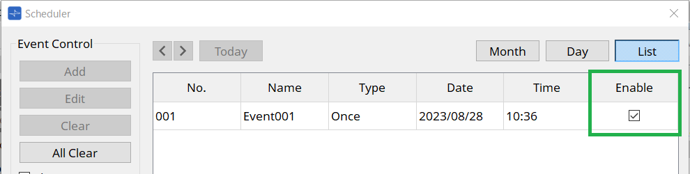
For details on settings and configuration, refer to the Audio Processor MTX5-D/MTX-3 "Scheduler dialog" in the user guide.
3.28. Conductor
3.28.1. Overview
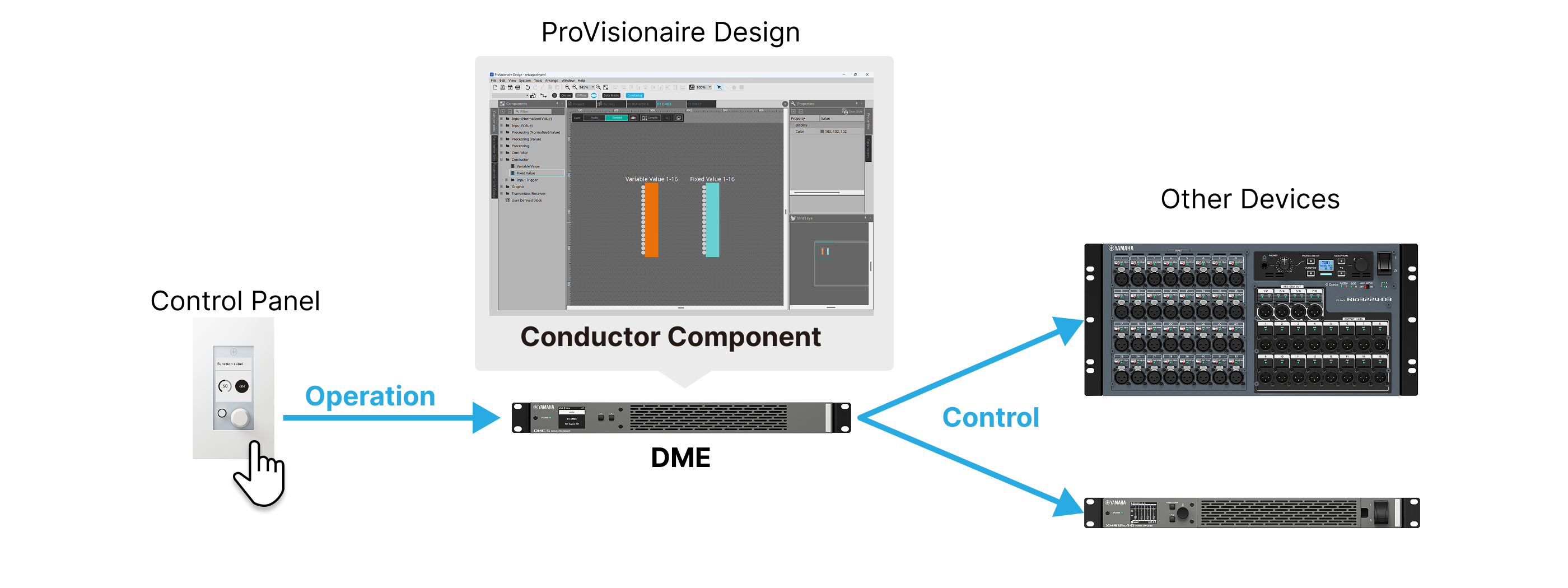
Conductor is a function that allows the DME to control peripheral devices. Conductor is provided as a Control component of the DME. The peripheral devices can be controlled by assigning presets/snapshots and parameters of DME’s peripheral devices to the Conductor component and then operating them with an external controller or Control component.
| As of V3.1, only the DME5/3 is supported. |
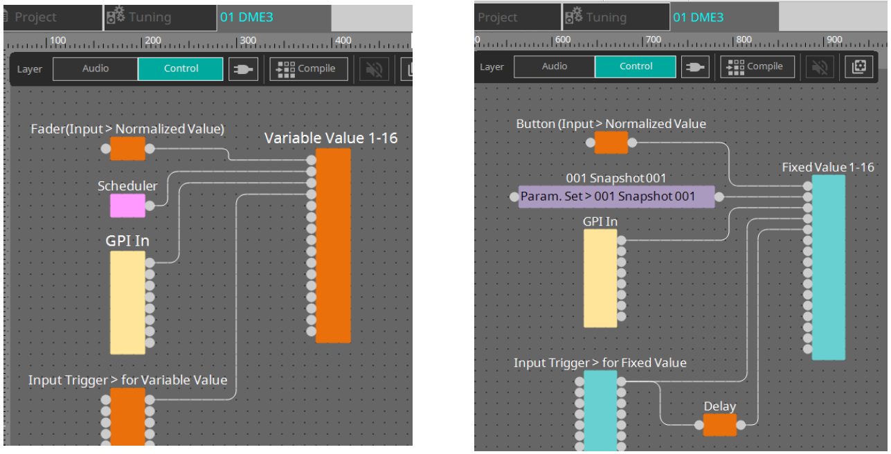
3.28.2. Workflow
Overall view
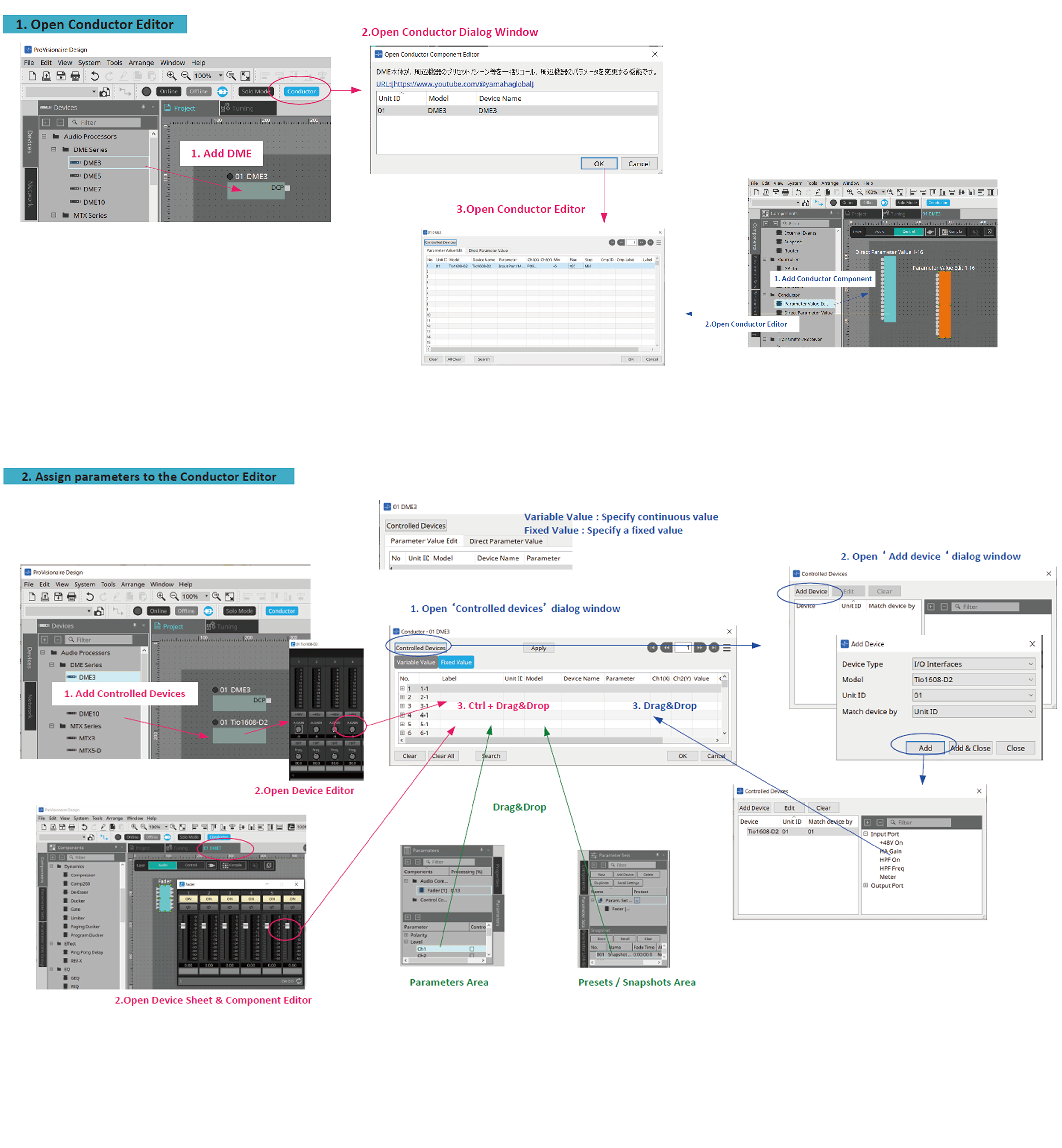
Procedure
-
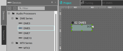
Place the DME on the Project sheet.
-
Click the [Conductor] button on the toolbar.

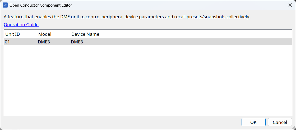
-
In the "Open Conductor Component Editor" dialog box that appears, select the DME that will run Conductor and click OK.
-
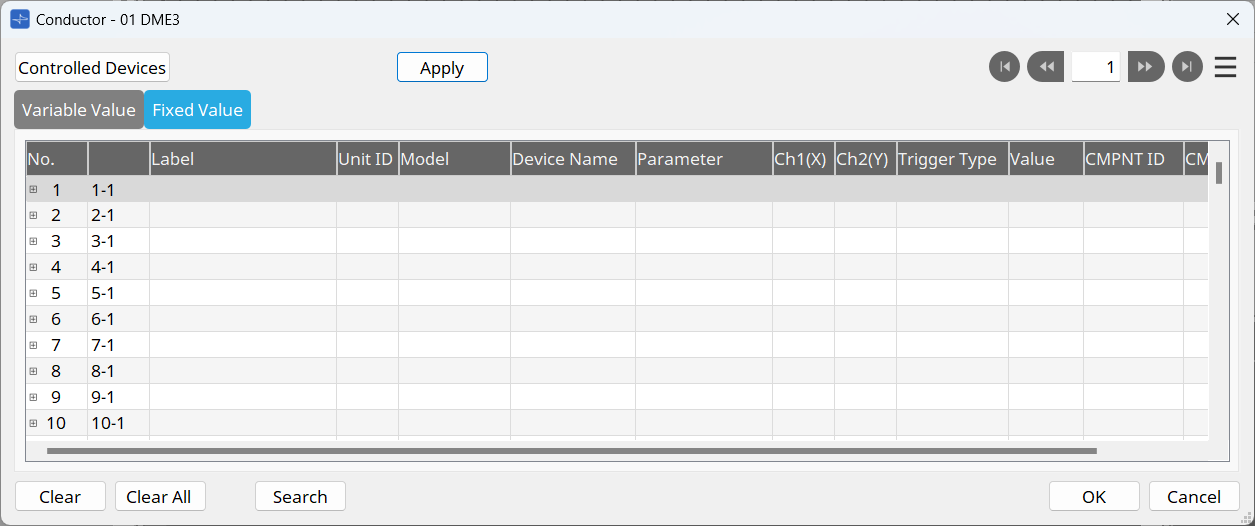
The Conductor component editor appears.
-
Register parameters and presets in Conductor.
There are two ways to register. Select the way according to your purpose.
◆ How to register from the device sheet
This is the basic registration method.
◆ How to register from Controlled Devices
Use this method for registering products not compatible with ProVisionaire Design (such as digital mixers).
◆ How to register from the device sheet
| Registration target | Registration source | How to register |
|---|---|---|
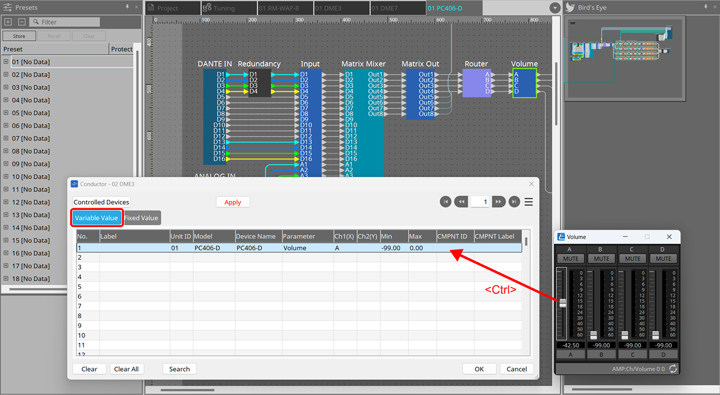
|
Continuously-varying
|
Component editor |
Hold down
|
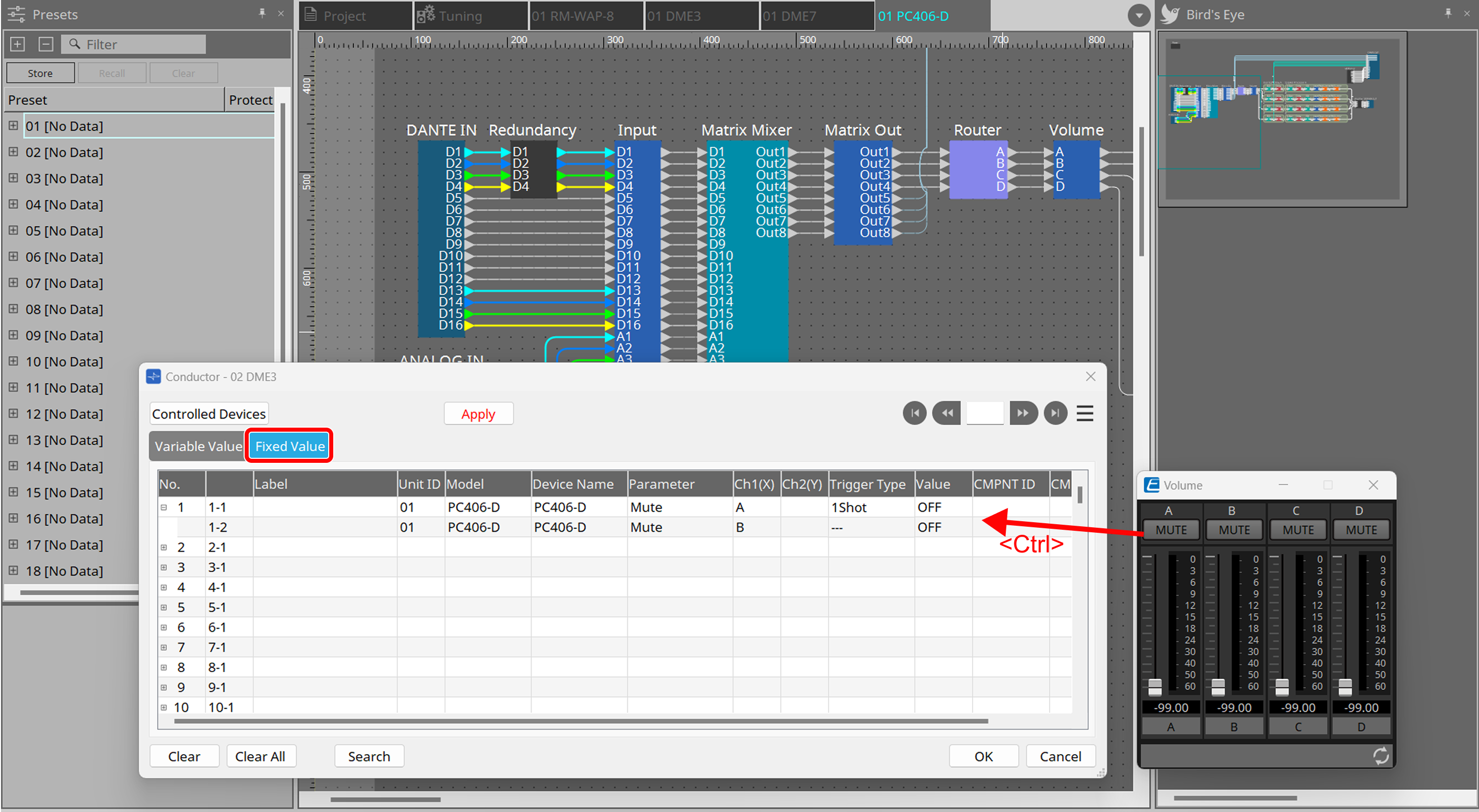
|
Fixed parameter value
|
Component editor |
Hold down
|
|
Snapshot
|
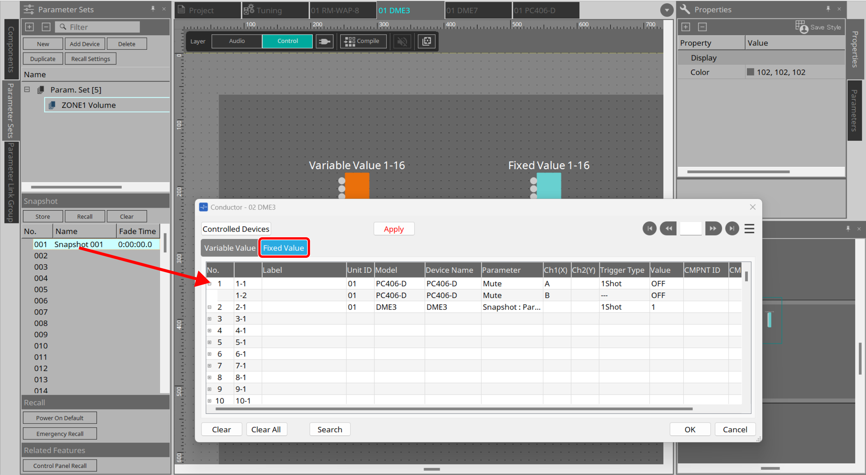
Parameters area |
Drag and drop the target item onto “Fixed Value” in the Conductor component editor.
|
| For the difference between "Fixed Value" and "Variable Value," refer to "Component types." |
Once you have completed the registration, proceed to step 6 .
◆ How to register from Controlled Devices
5-1. Click the [Controlled Devices] button in the Conductor component editor.
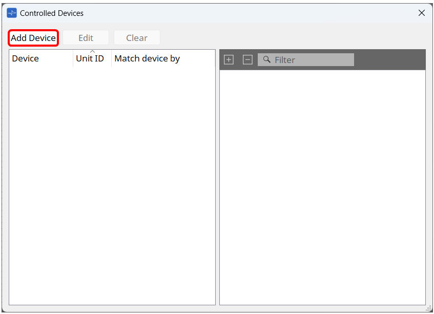
5-2. Click the [Add Device] button in the “Controlled Devices” dialog box.
5-3.
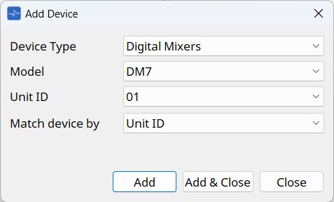
In the "Add Device" dialog box, select the device you want to control.
You can consecutively add devices by pressing the [Add] button.
Once you have added all the devices, click the [Close] button to close the dialog box.
The [Controlled Devices] dialog box displays the parameters and presets.
5-4. Drag and drop the parameters or presets you want to register into "Fixed Value" or "Variable Value" of the Conductor component editor.
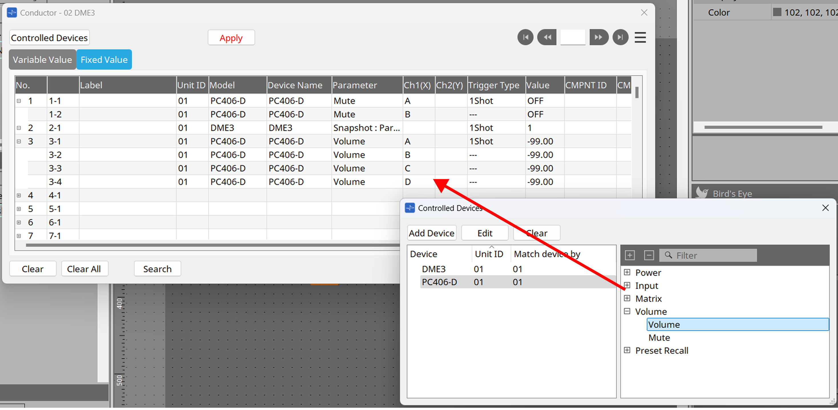
| For the difference between "Fixed Value" and "Variable Value," refer to "Component types." |
-
Set the registered parameters and presets.
Double-click each column in the list to set the value and label. You can also change the channel after assignment. Click the [Apply] button to apply the settings.
-
Once you have completed all registration and settings, click the [OK] button.
Clicking the [OK] button will apply the settings and close the screen. -
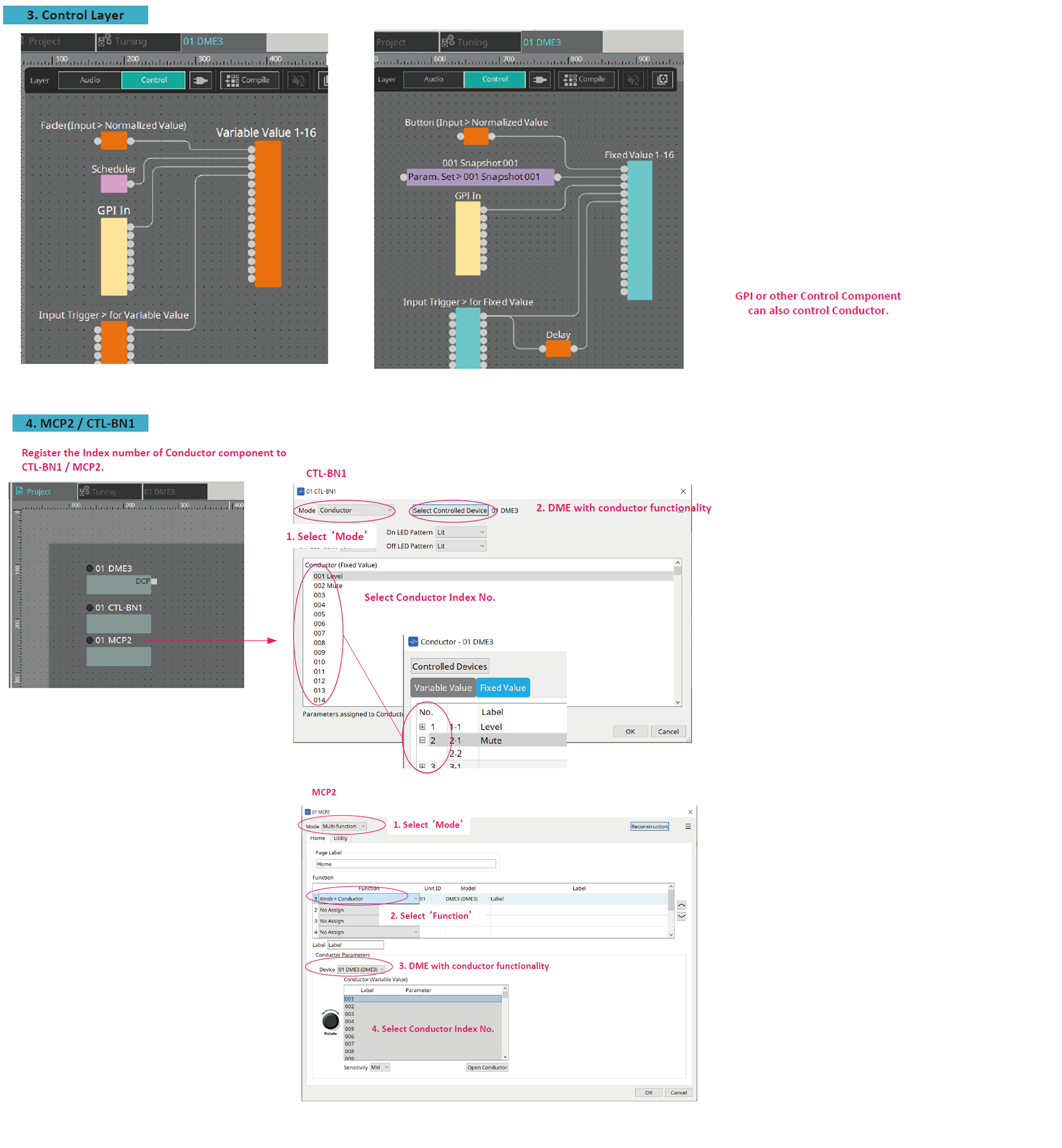
Assign them to the controller.
Conductor supports the following controllers (as of ProVisionaire Design V3.1).
For the assignment methods, refer to the chapter of each controller in "ProVisionaire Design User Guide."-
MCP2
-
CTL-BN1
-
Advanced usage
In addition to running Conductor using an external controller, you can also run it using the DME’s Control component.
Conductor also provides Input Trigger > for Variable Value and for Fixed Value components that are ideal for controlling Conductor components.
-
Place the Conductor component on the Control layer of the DME.
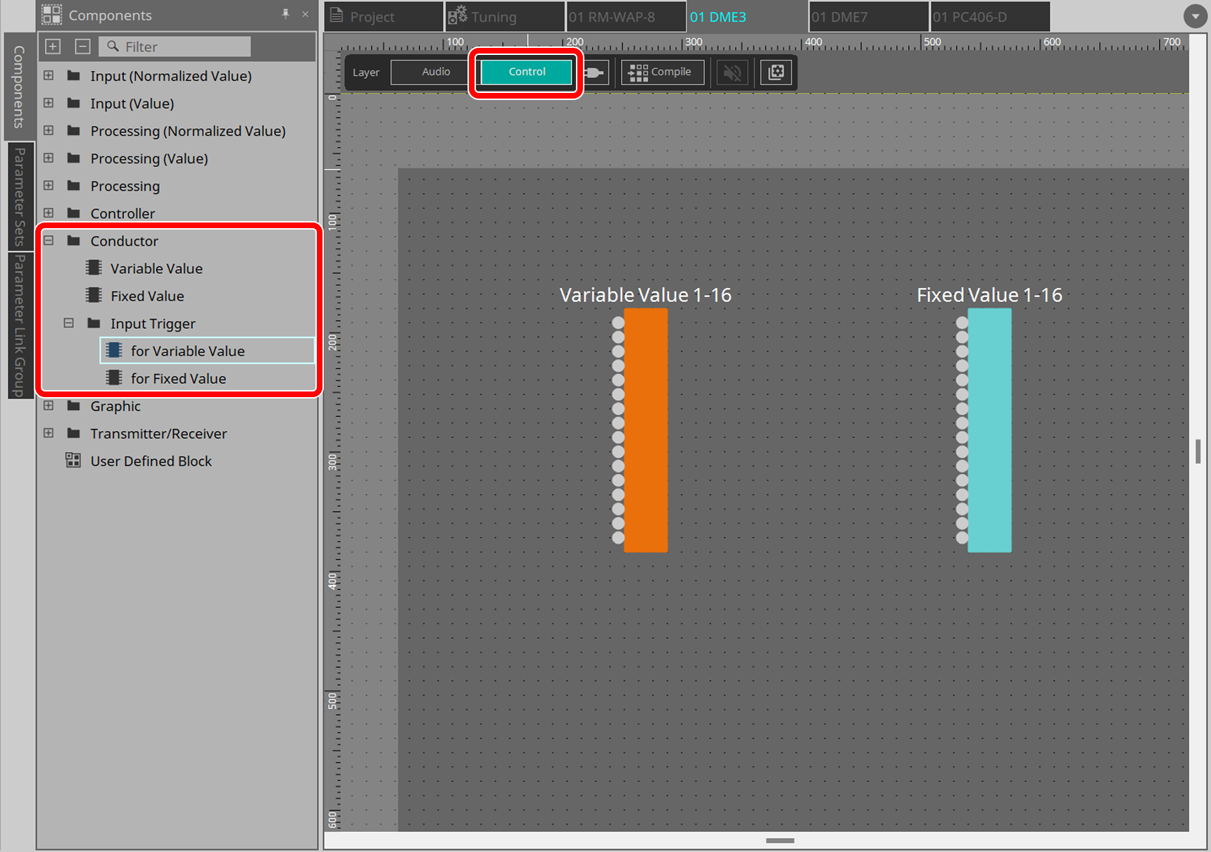
-
Wire logic-type components such as schedulers and triggers to any list number in the Conductor component.
3.28.3. Component types
Conductor has two component types. Moreover, each component has an Input Trigger component that acts as a trigger to activate the Conductor component.
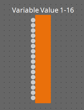
Variable Value component
Variable Value is intended to change continuously-varying parameters.
Specify continuously-varying parameters such as Level of a DME or peripheral device.
This component is intended to be operated using an encoder of an external controller or a fader-type control component.
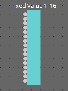
Fixed Value component
Fixed Value is intended to recall a preset or snapshot and change a parameter to a specific value.
Specify the preset or snapshot number of a DME or peripheral device, or a fixed parameter value.
This component is intended to be operated using buttons on an external controller or button-type control components.

For details on each component, refer to the sections below.
-
Input Trigger
3.28.4. Various screens
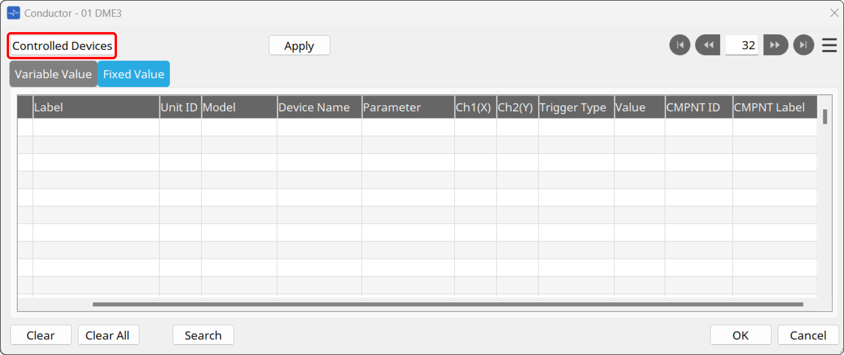
Conductor component editor
To display the screen of this editor, click the
![]() button on the toolbar or double-click the Conductor component placed on the design sheet of the DME.
button on the toolbar or double-click the Conductor component placed on the design sheet of the DME.
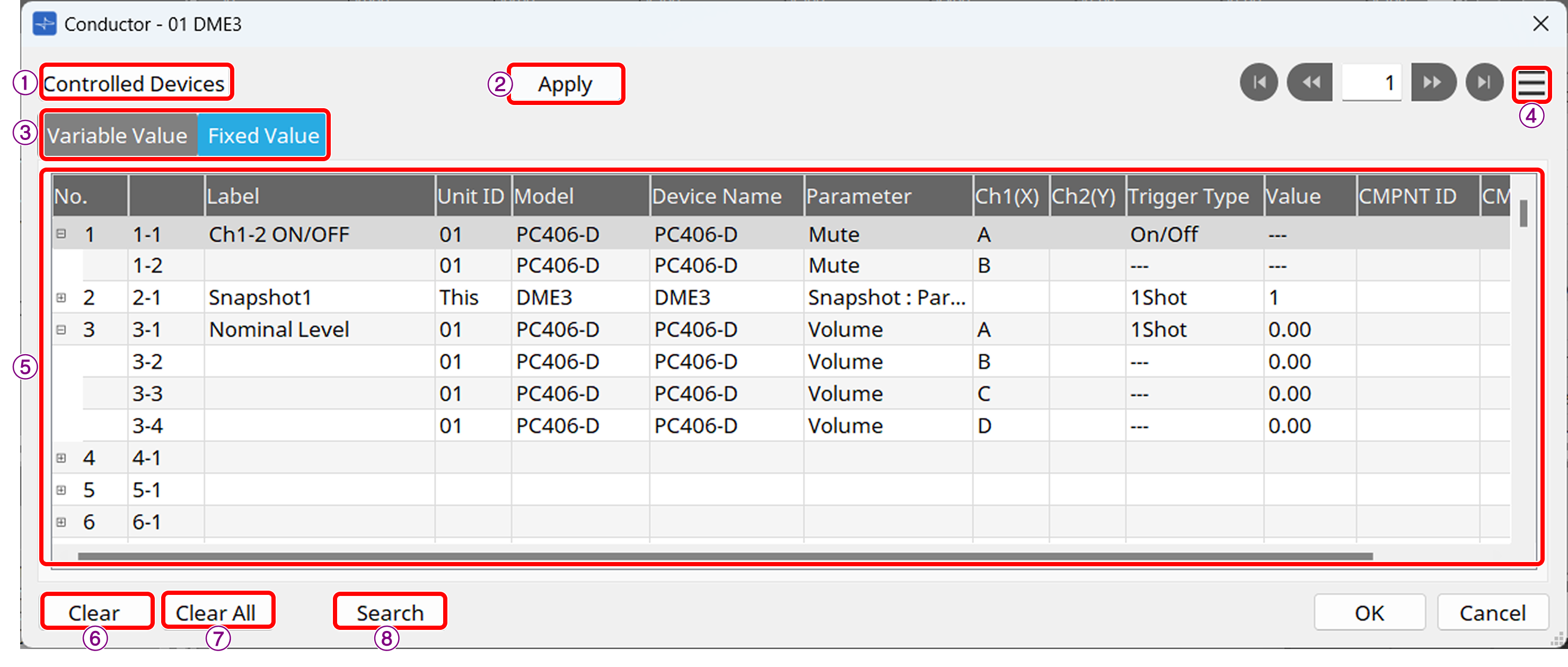
① [Conductor Devices] button
Displays
the "Controlled Device" dialog box
.
② Apply button
Applies the edits.
③ [Variable Value/ Fixed Value] tab
Click this tab to switch between Variable Value and Fixed Value.
For the difference between the two types, refer to
"Component type."
④ [Menu] button or context menu
-
Find
You can switch the sheet and select the desired component editor. -
Cut
Cuts the selected row. -
Copy
Copies the selected row. -
Paste
Pastes the copied row. -
Insert
Inserts the copied row. -
Delete
Deletes the selected row. -
Swap
-
Source: The selected row will be the source of the swap.
-
Destination: The selected row will be swapped with the row selected in Source.
-
-
Cleaning
Click this button to delete the rows displayed in red.
For free configuration devices, if a registered row becomes invalid for the following reasons, the relevant section will be displayed in red.
・The row has been deleted from the project sheet.
・The Unit ID has been changed.
・The component has been deleted.
・The number of channels of the component has been reduced. -
Export
Exports the Conductor settings and saves them to a file. -
Import
Imports a saved file.
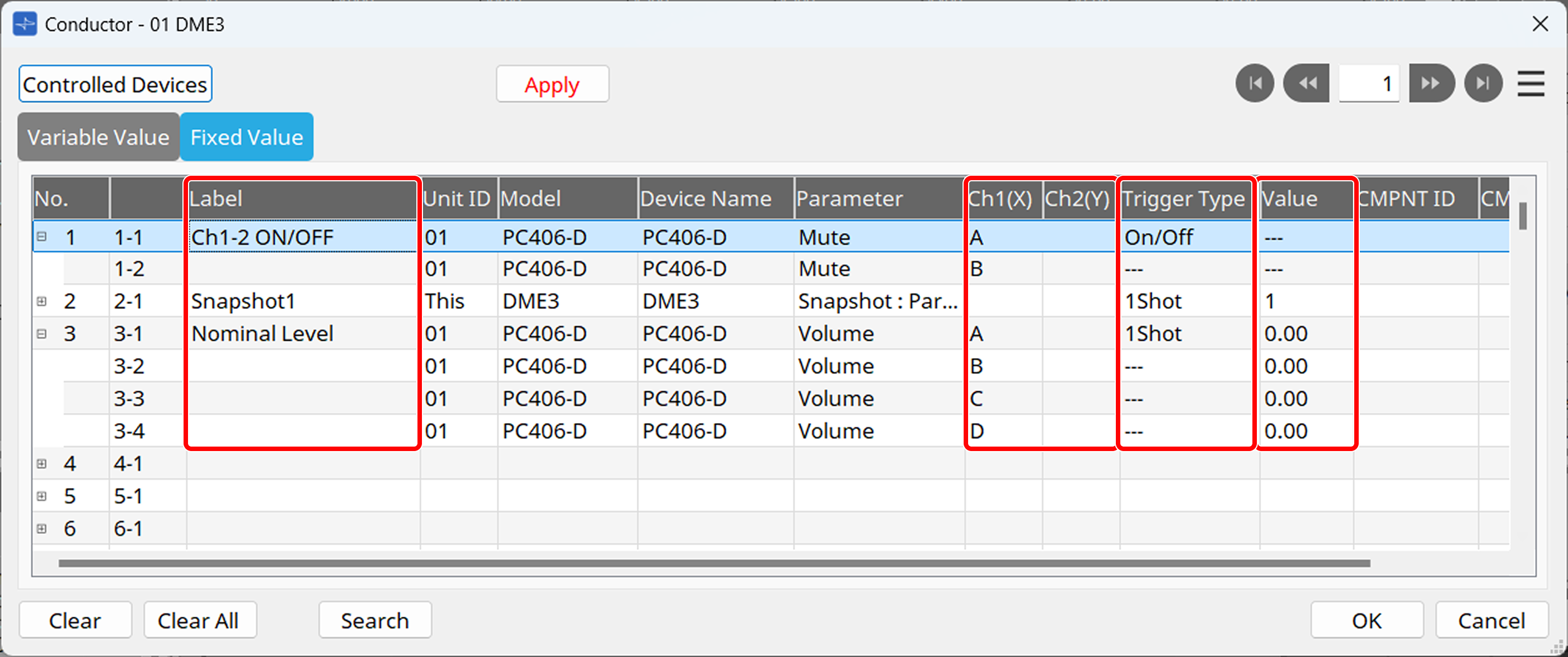
⑤ List
Click on each item to change the settings. The items that can be edited vary depending on the parameter.
-
No./Unit ID/Model/Device Name/Parameter
Shows information about the assigned devices and parameters. The information cannot be edited here. -
Label field
You can enter a label. This label will appear on the settings screen for assigning to an external controller. -
Ch1 (X)/Ch2 (Y) field
Specifies the channel. -
Min/Max field (only for Variable Value)
Sets the minimum and maximum values for the level. -
Trigger Type field (only for Fixed Value)
Specifies the execution method.-
1Shot: Executes the same value each time you press the button.
-
ON/OFF: Toggles between ON and OFF each time you press the button.
Parameters other than ON and OFF (such as a fixed level value) cannot be set.
-
-
Value field (only for Fixed Value)
Specifies the fixed value of the parameter. -
CMPNT ID field (only for the DME series)
Shows the component ID. The information cannot be edited here. -
CMPNT Label field (only for the DME series)
Shows the component label. The information cannot be edited here.
⑥ [Clear] button
Deletes the selected parameter.
⑦ [Clear All] button
Deletes all parameters from the list.
⑧ [Search] button
Shows the "Search" dialog box.
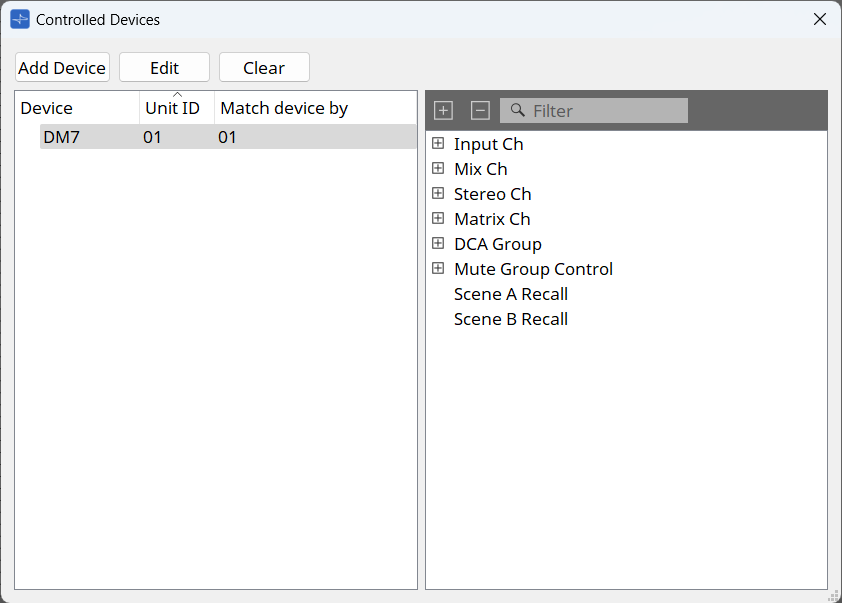
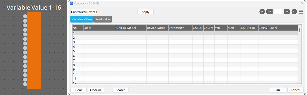
Controlled Devices dialog box
This dialog box can be displayed with the [Controlled Devices] button in
the Conductor component editor
.
It shows the parameters to be registered in the Conductor editor.

① [Add Device] button
Click this button to display
the "Add Device" dialog box
.
② [Edit] button
Click this button to display
the "Match Device by" dialog box
.
③ [Clear] button
Click this button to delete the selected device.
④ [Controlled Devices] area
Shows the added devices.
⑤ [Parameter] area
Shows parameters of the device selected in the [Device] area.
The parameters can be registered in Conductor by dragging and dropping them into the Conductor editor.
Add Device dialog box
This dialog box can be displayed with the [Add Device] button that will be displayed by clicking the [Controlled Devices] button in the Conductor component editor . On this screen, you can add devices to be controlled by Conductor.
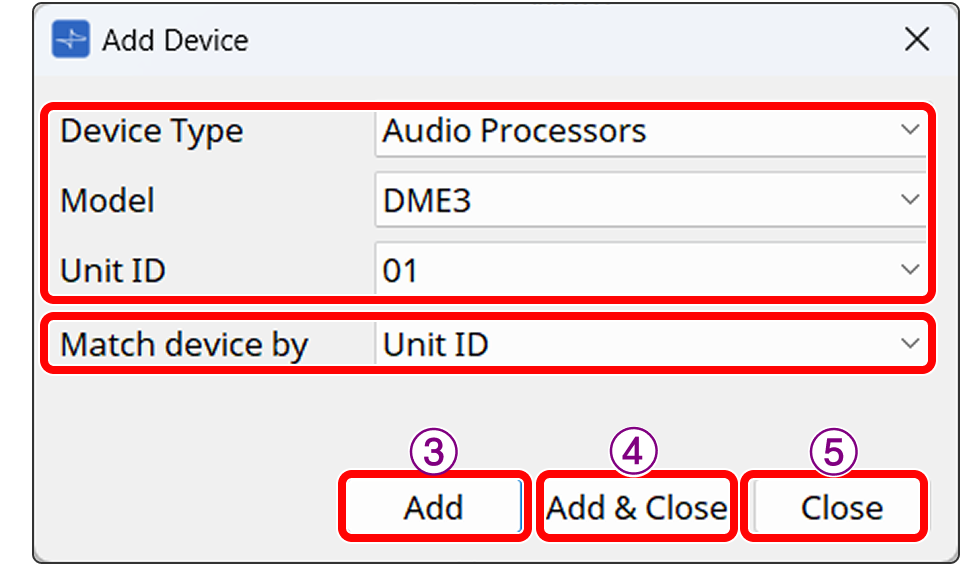
① Device Type/Model/Unit ID
Specifies the device to be assigned. You can also select devices that will not be controlled by ProVisionaire Design.
② [Match Device by] list box
Selects whether Conductor discovers devices by Unit ID or by IP Address.
③ [Add] button
Adds a device to Controlled Device.
④ [Add&Close] button
Adds a device to Controlled Device and closes the dialog box.
⑤ [Close] button
Closes the dialog box without adding the device to Controlled Device.
Match Device by dialog box
This dialog box can be displayed with the [Edit] button that will be displayed by clicking the [Controlled Devices] button in the
Conductor component editor
.
You can change "Match Device by" of the device selected in the list. [Match Device by] is how Conductor discovers devices. You can choose either Unit ID or IP Address.
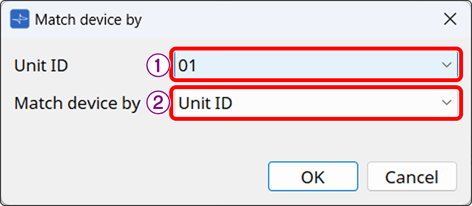
① [Unit ID] list box
Changes the Unit ID of the device selected in the [Controlled Devices] area.
You cannot change the Unit ID to one that overlaps with an already-placed device.
② [Match Device by] list box
Changes [Match Device by] of the device selected in the [Controlled Devices] area.
You cannot change the IP address to one that overlaps with an already-placed device.
Search dialog box
This dialog box can be displayed with the [Search] button in
the Conductor component editor
.
On this screen, you can search the Conductor editor list.
For Variable Value and Fixed Value, the tab currently displayed for the respective component will be searched.
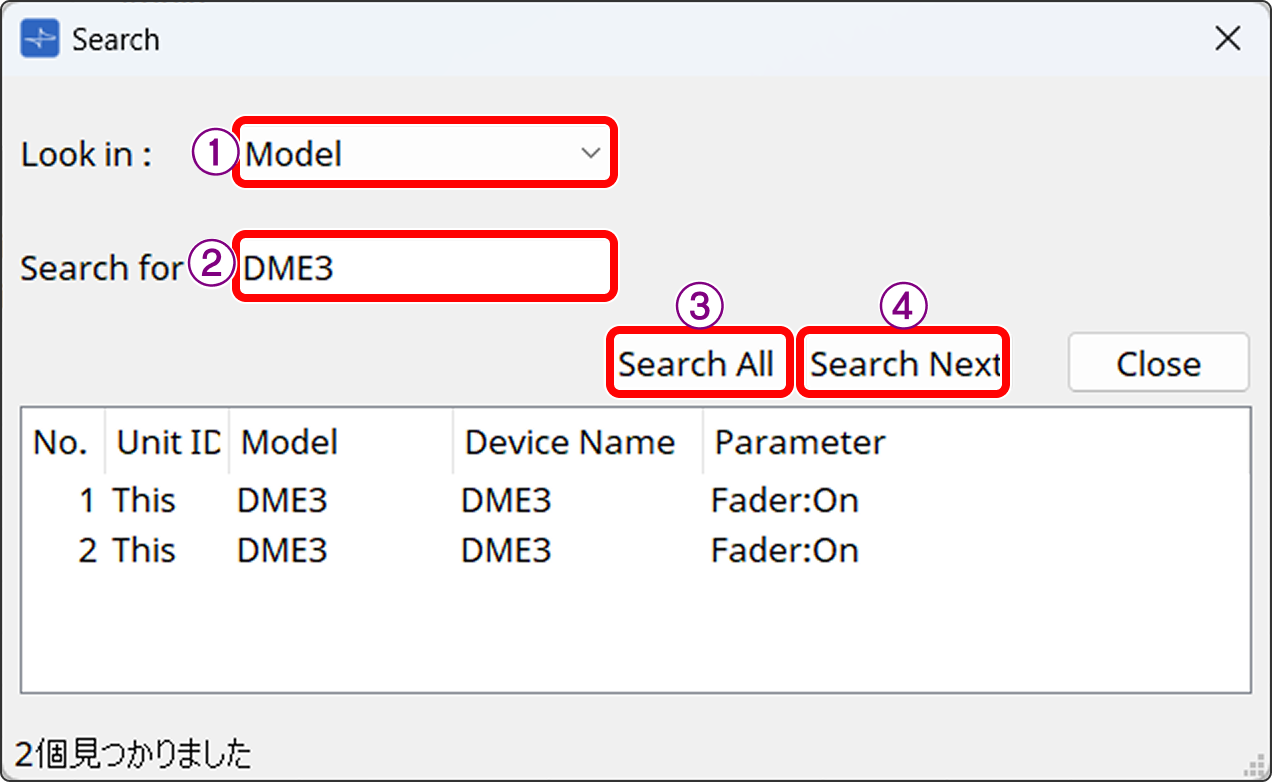
① [Look in] list box
Select the search category from Model, Device Name, and Parameter.
② [Search for] list box
Enter the search term.
③ [Search All] button
Click this button to display the search results in the box below.
④ [Search Next] button
Identifies the corresponding row of the search results and shows it in order on the Conductor list.
3.28.5. Supported product list
| Device Type | Model |
|---|---|
|
Power Amplifiers |
XMV Series
|
|
I/O Interfaces |
Tio1608-D2
|
|
Digital Mixers |
TF-Rack
|
|
Audio Processors |
DME Series
|
|
Powered Speaker |
VXL1-16P
|
|
Microphones |
RM-CG
|
|
Controller |
MCP1
|
|
Power Amplifiers |
XMS Series
|
|
I/O Interfaces |
Rio1608-D3/Rio3224-D3
|
|
Digital Mixers |
DM3/DM3 Standard
|
|
Audio Processors |
DME Series
|
|
Powered Speaker |
VXC2P
|
|
Microphones |
RM-WAP-8/16
|
|
Controller |
MCP2
|
As of ProVisionaire Design V3.1
3.29. Conductor: Variable Value
Variable Value is intended to change continuously-varying parameters in the Conductor function.
Specify continuously-varying parameters such as Level of a DME or peripheral device.
This component is intended to be operated using an encoder of an external controller or a fader-type control component.
3.29.1. "Conductor" component editor
Refer to "Conductor" component editor .
Parameter type of input/output value for each port
|
Input Value |
Operation |
Output Value |
|||||
|---|---|---|---|---|---|---|---|
|
Type |
Range |
Input Port Name |
Trigger/Processing |
Output Port Name |
Type |
Range |
|
|
Normalized |
0~256 |
001 to 256 |
- |
- |
- |
- |
|
3.30. Conductor: Fixed Value
Fixed Value is intended to recall a preset or snapshot and change a parameter to a specific value in the Conductor function.
Specify the preset or snapshot number of a DME or peripheral device, or a fixed parameter value.
This component is intended to be operated using buttons on an external controller or button-type control components.
3.30.1. "Conductor" component editor
Refer to "Conductor" component editor .
Parameter type of input/output value for each port
|
Input Value |
Operation |
Output Value |
|||||
|---|---|---|---|---|---|---|---|
|
Type |
Range |
Input Port Name |
Trigger/Processing |
Output Port Name |
Type |
Range |
|
|
Value |
Num |
OFF:0、ON:1 |
001 to 256 |
- |
- |
- |
- |
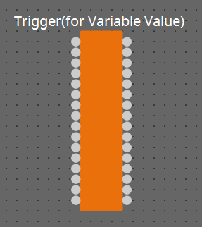
3.31. Conductor: Input Trigger for Variable Value
for Variable Value is intended to establish a connection to a Variable Value component and act as a trigger for the Conductor function.
3.31.1. "for Variable Value" component editor
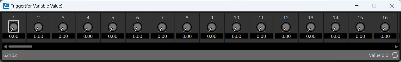
A normalized value between 0.00 and 1.00 will be output.
![]()
Parameter type of input/output value for each port
|
Operation |
Output Value |
|||
|---|---|---|---|---|
|
Input Port Name |
Trigger/Processing |
Output Port Name |
Type |
Range |
|
001 to 256 |
Trigger: Fader |
001 to 256 |
Normalized |
0.00 to 1.00 |
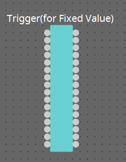
3.32. Conductor: Input Trigger for Fixed Value
for Fixed Value is intended to establish a connection to a Fixed Value component and act as a trigger for the Conductor function.
3.32.1. "for Fixed Value" component editor
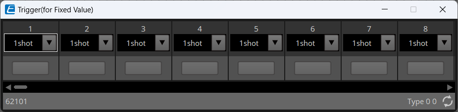
List box
-
On/Off: Outputs the On/Off status.
-
1shot: Always outputs 1.
Parameter type of input/output value for each port
|
Operation |
Output Value |
|||
|---|---|---|---|---|
|
Input Port Name |
Trigger/Processing |
Output Port Name |
Type |
Range |
|
001 to 256 |
Trigger: Button |
001 to 256 |
On/Off |
OFF:0 ON:1 |
|
1shot |
1 |
|||
3.33. Mute Group
Mute Group enables grouping of multiple microphone peripherals and conferencing applications on the PC so that the mute status is synchronized. You can also link the status of an online meeting with the LED display of peripheral devices. Only one component can be placed. Only the DME5/3 is supported.

3.33.1. "Mute Group" component editor
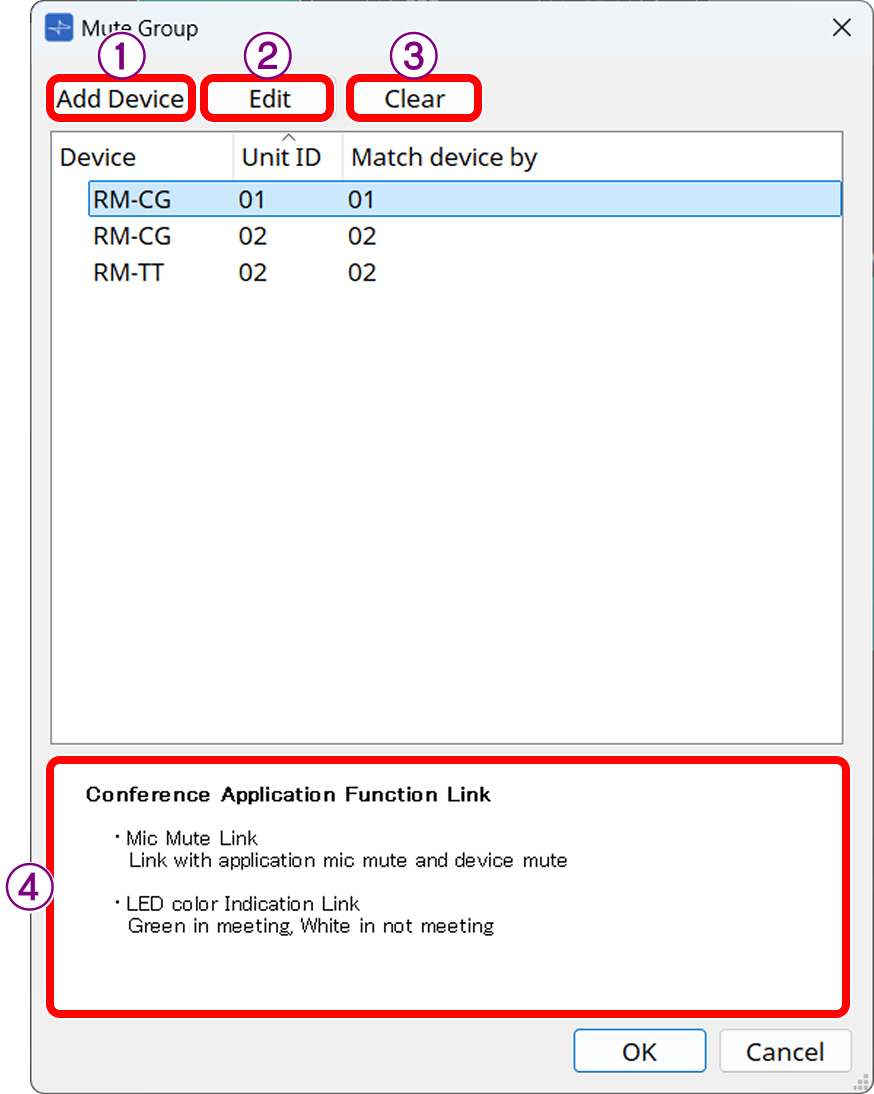
① Open
the Add Device dialog box
and select the device you want to control.
②
The “Match Device by” dialog box
appears.
③ Delete the selected device.
④ A description of the linkage function between the selected device and the conferencing application is displayed.
3.33.2. Add Device dialog box
This dialog box can be displayed with the [Add Device] button in the Mute Group component editor. On this screen, you can add devices to be controlled by Mute Group. All the added devices will automatically link with the conferencing application on the PC connected via USB to Host.
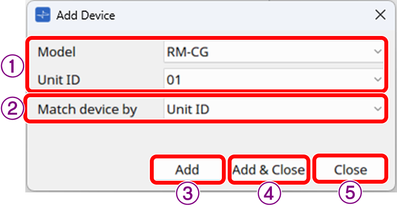
① Model/Unit ID
Specifies the device to be assigned.
② [Match Device by] list box
Select whether the controller discovers devices by Unit ID or by IP Address.
③ [Add] button
Adds a device to Controlled Device.
④ [Add&Close] button
Adds a device to Controlled Device and closes the dialog box.
⑤ [Close] button
Closes the dialog box without adding the device to Controlled Device.
Match Device by dialog box
This dialog box can be displayed with the [Edit] button in the Mute Group component editor.
You can change "Match Device by" of the device selected in the list. [Match Device by] is how Mute Group discovers devices. You can choose either Unit ID or IP Address.
① [Unit ID] list box
Changes the Unit ID of the device selected in the [Controlled Devices] area.
You cannot change the Unit ID to one that overlaps with an already-placed device.
② [Match Device by] list box
Changes [Match Device by] of the device selected in the [Controlled Devices] area.
You cannot change the IP address to one that overlaps with an already-placed device.
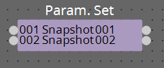
3.34. Parameter Set
Recalls a snapshot when there is an input on the input port.
For information on how to add components to the control layer, refer to
"Controlling a Snapshot and ParamSet in the control component" in the user guide.
(For 2 inputs)
INPUT
Snapshot 001 : The input value to recall a snapshot (any number)
Snapshot 002 : The input value to recall a snapshot (any number)
OUTPUT
Snapshot 001 : Outputs 1 when a snapshot is recalled
Snapshot 002 : Outputs 1 when a snapshot is recalled
Parameter types of the input/output values for each Port
|
Input Value |
Operation |
Output Value |
|||||
|---|---|---|---|---|---|---|---|
|
Type |
Range |
Input Port Name |
Trigger/Processing |
Output Port Name |
Type |
Range |
|
|
Value |
Num |
Any value |
● Snapshot(001–100) |
- |
- |
- |
- |
|
- |
- |
- |
- |
- |
● Snapshot(001–100) |
- |
1 |
|
Value |
Num |
0–100 |
Sel |
- |
- |
- |
- |
3.35. Snapshot
Recalls a snapshot triggered by an input.
Refer to
"Controlling a Snapshot and ParamSet in the control component" in the user guide
for information on adding components to the control layer.
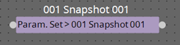
INPUT
Snapshot 001 : The input value to recall a snapshot (any number)
OUTPUT
Snapshot 001 : Outputs 1 when a snapshot is recalled
Parameter types of the input/output values for each Port
|
Input Value |
Operation |
Output Value |
|||||
|---|---|---|---|---|---|---|---|
|
Type |
Range |
Input Port Name |
Trigger/Processing |
Output Port Name |
Type |
Range |
|
|
Value |
Num |
Any value |
● Snapshot(001–100) |
- |
- |
- |
- |
|
- |
- |
- |
- |
- |
● Snapshot(001–100) |
- |
1 |
Yamaha Pro Audio global website
https://www.yamahaproaudio.com/
Yamaha Downloads
https://download.yamaha.com/
|
© 2023 Yamaha Corporation
|