Names and Functions of Respective Parts
4. Names and Functions of Respective Parts
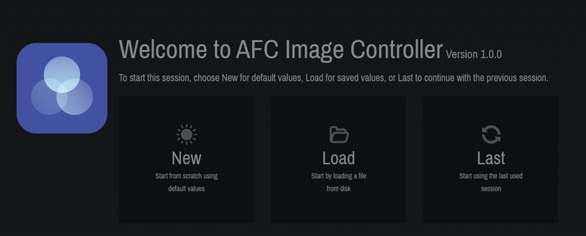
4.1. Welcome Screen
At startup, you can choose to create a new file, open an existing file, or open the previous project file.
-
[New] : A new project file will be created.
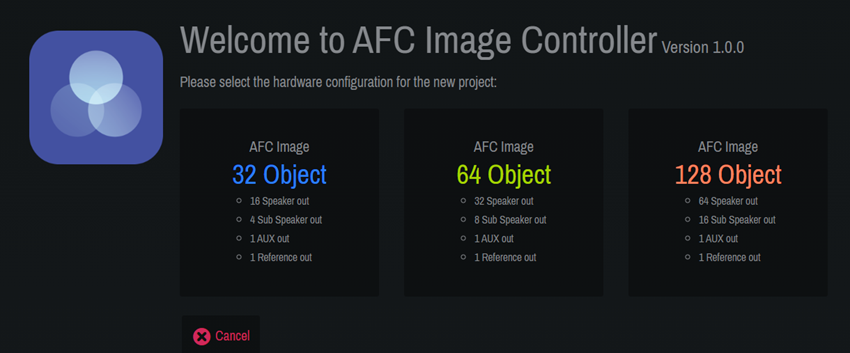
Select the component according to your license.
The number of required licenses varies depending on the device to be connected.
The DME7 requires the optional expansion kit "DEK-AFC-I" (sold separately). With the DME10, the inputs can be expanded up to 128 channels and the outputs up to 64 channels by purchasing the additional "NX-AFC-I."Refer to the table below for the components that can be added depending on the number of licenses.
Hardware 0 licenses 1 license 2 licenses DME7
Not available
32 in - 16 out × 1
64 in - 32 out × 1
or
32 in - 16 out × 1DME10
32 in - 16 out
64 in - 32 out × 1
or
32 in - 16 out × 2128 in - 64 out × 1
or
64 in - 32 out × 2
or
32 in - 16 out × 3 -
[Load] : The saved project file ".afciprj" will be read.
-
[Last] : The state when the software was closed the last time will be restored.
4.2. Common to All Windows
AFC Image Controller consists of the "main window," "window display selector," "function window display area," and "status area."
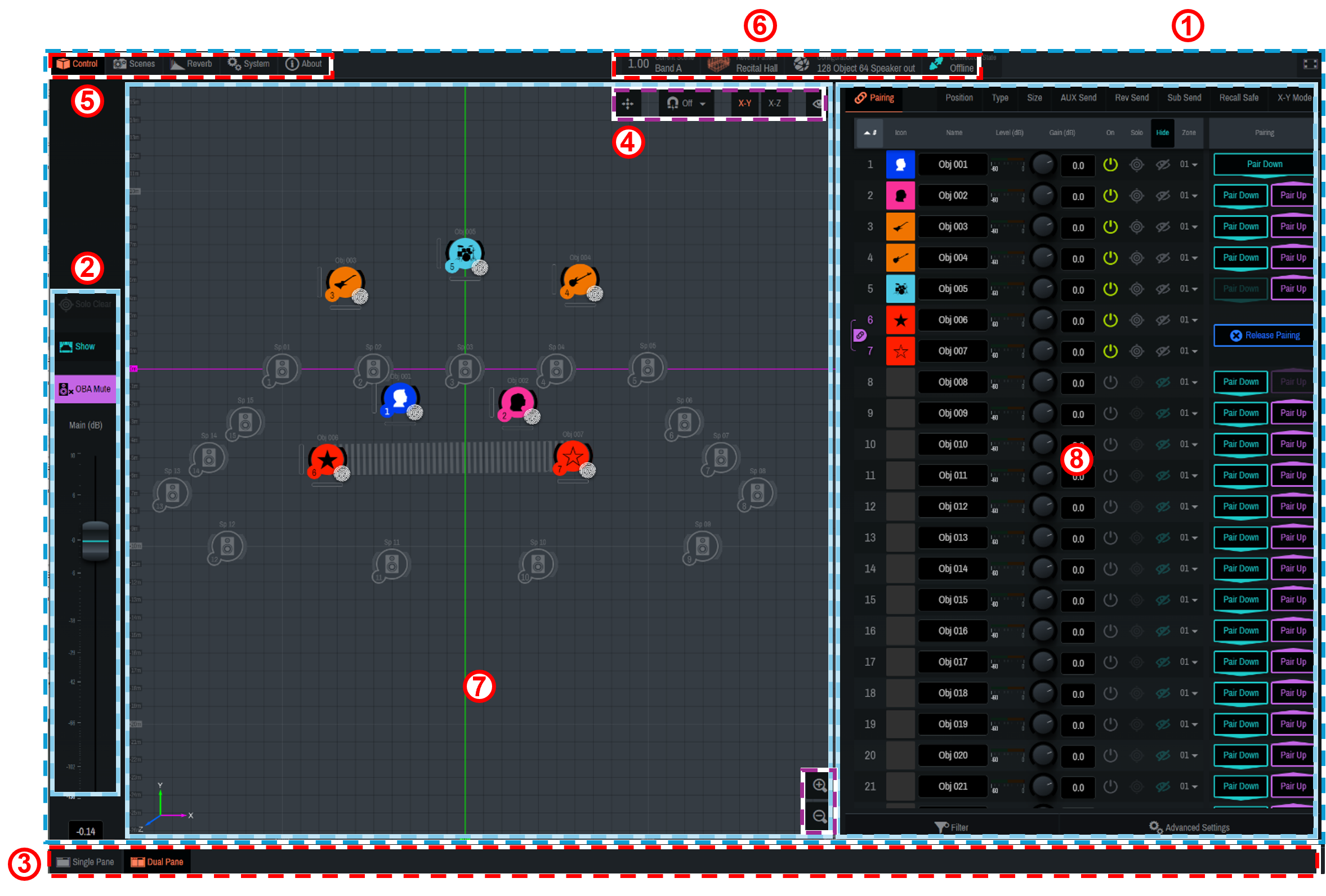
①
"Main window"
The "main window" contains the main fader section, 2D Stage window, and Controls window. The display will differ depending on the display size of the software.
Click "
![]() " to view in full screen.
" to view in full screen.
②
"Main fader section"
You can control on/off of the Show mode and the main volume.
-
 [Solo Clear]
All Solo settings on sound objects and speakers will be cleared. -
 [Show]
This item will be used during real performances of musicals, concerts, or such occasions.
Turning on this item enables the Show mode and restricts the Solo function. In addition, the following functions are also restricted:-
OBA Mute
-
Zone settings for sound objects
-
Zone settings for 3D reverb
-
Import function for Speakers and SubSpeakers
-
Changing the coordinates of Speakers and SubSpeakers, and on-off switching
-
Distance Attenuation and Precision in Advanced Settings
If the same AFC Image component is connected to AFC Image Controllers of multiple computers, changes to the following items will also be restricted:
-
Network Interface, Device, Component/Online, and Configuration under [System] - [Settings]
-
-
-
 [OBA MUTE]
OBA Main will be muted. -
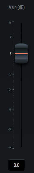
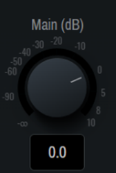 [Main(dB)]
The OBA Main volume will be adjusted.
The volume graphic changes depending on the window size.
③
"Window display selector"
The content displayed in the main window will be switched.
-
 [Single Pane]
The 2D Stage window or Controls window will be maximized. -
 [2D Stage]
Only the 2D Stage window will be displayed in the main window. -
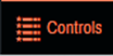 [Controls]
Only the Controls window will be displayed in the main window. -
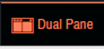 [Dual Pane]
The two-screen view of the 2D Stage window and the Controls window will be displayed.
The 2D Stage window displays the current sound objects and the positions of Speakers and SubSpeakers.
You can also place a sound object, Speaker, or SubSpeaker by dragging it with the mouse.
④ "2D Stage operation"
| Button Illustration | Function | |
|---|---|---|
|
|
Displays the origin (X, Y, Z = 0). |
|
|
|
Sets the interval at which sound objects are moved when dragged in the 2D Stage window. The movement interval can be selected from 0.1, 0.2, 0.5, and 1.0 (m). When this button is set to off, the movement interval will be 0.01 m. |
|
|
|
Switches the display of the 2D Stage window between X-Y (plan view) and X-Z (section view). |
|
|
|
Switches show/hide on the 2D Stage. |
|
|
|
ID number |
|
|
|
Name |
|
|
|
Level(dB) |
|
|
|
Size |
|
|
|
Speakers、SubSpeakers |
|
|
|
Enlarges or reduces the display area. |
|


⑤
"Function window"
Functions that can be executed by AFC Image Controller are grouped by settings in the function window.
-
 [Control]
Set the parameters of sound objects. -
 [Scenes]
Store or recall scenes. -
 [Reverb]
Set 3D reverb and EQ. -
 [System]
Configure system-wide settings, such as output adjustment, connection to a DME7/10, and saving project files. -
 [About]
Check the version of AFC Image Controller.
⑥
Status area
The status area displays the current status of each item.
-
 [Current Scene] button
The current scene will be displayed. Click this button to move to [Scenes]. -
 [Reverb Pattern]
The current reverb pattern will be displayed. Click this button to move to [Reverb]. -
 [Configuration]
The current configuration will be displayed. Click this button to move to [System]-[Settings]. -
 [Connection State]
The connection status with the device will be displayed. Click this button to move to [System]-[Settings].
⑦ 2D stage window
⑧ Controls window
4.3. Controls Window
Set the parameters for each sound object.
4.3.1. Setup of sound objects
| Setting Item | Overview |
|---|---|
|
#ID number |
The ID number of the sound object. Click # at the top to sort by ID number. |
|
Icon |
Sets the icon and color tone for each sound object. |
|
Name |
Displays/allows you to edit the name of each sound object. Click Name at the top to sort by name. |
|
Level(dB) |
Displays the input level of each sound object. |
|
Gain(dB) |
Adjusts the gain of each sound object. |
|
On |
Sets the on/off setting for each sound object. |
|
Solo |
Sets the Solo on/off setting for each sound object. Click "Solo" at the top to turn on/off all sound objects at once. The Solo function is restricted in the Show mode. |
|
Hide |
Sets the display of sound objects in the 2D Stage window. Click [Hide] at the top to set the display of all sound objects at once. |
|
Zone |
Displays the currently assigned zone. Use the down arrow to change the zone. |
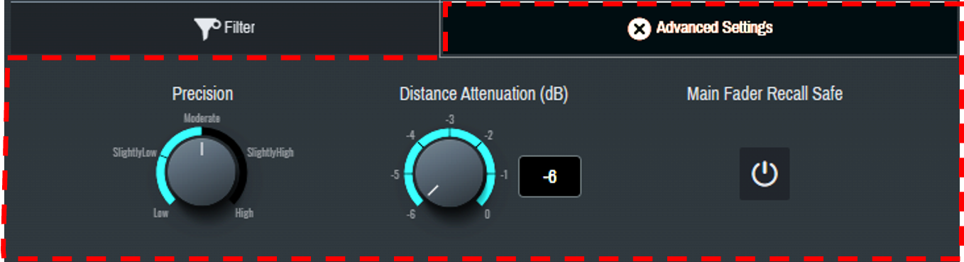
4.3.2. Advanced Settings
Configure the advanced function settings of sound objects. The settings will be reflected in all sound objects.
| Function | Explanation |
|---|---|
|
Precision |
Sets the precision of sound object localization in five levels.
|
|
Distance Attenuation(dB) |
Sets the distance attenuation when a sound object is localized outside the speakers. The attenuation can be set from -6 to 0 dB. |
|
Main Fader Recall Safe |
Applies Recall Safe to [Main(dB)]. |
4.3.3. Filter
Narrow down the sound objects to be displayed. Multiple narrowing conditions can be selected.
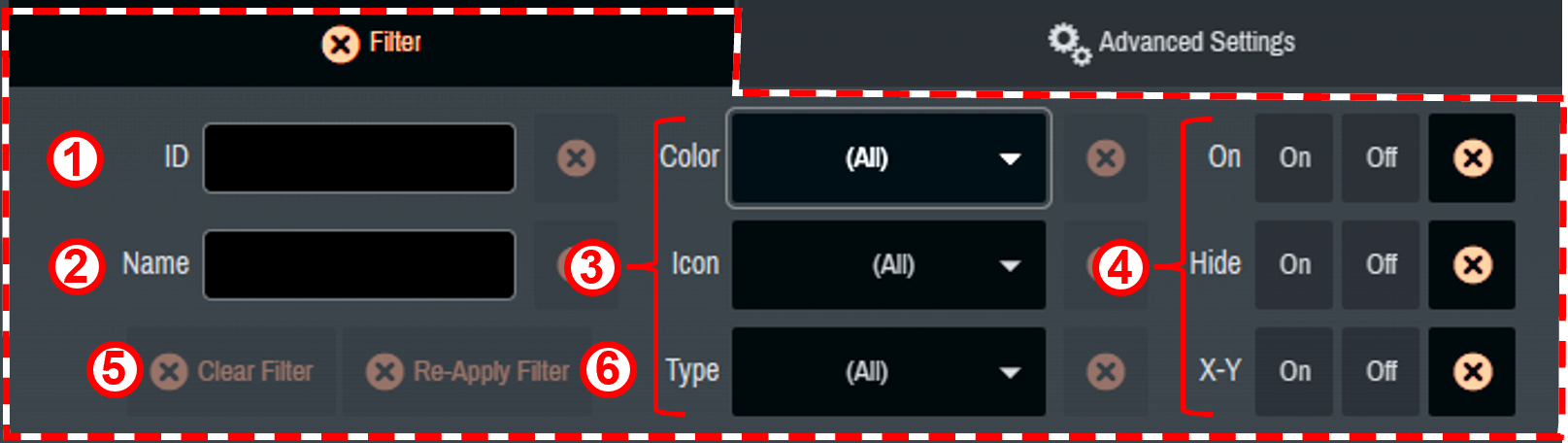
① The sound objects to be displayed are narrowed down to those meeting the condition entered in ID number.
② The sound objects to be displayed are narrowed down to those meeting the condition entered in Name.
③ The sound objects to be displayed are narrowed down to those meeting the conditions selected in Color, Icon, and Type.
④ The sound objects to be displayed are narrowed down based on On, Hide, and on/off of X-Y Mode.
⑤ All narrowing conditions are reset.
⑥ The previously selected narrowing conditions are displayed again.
4.3.4. Sound object parameter settings
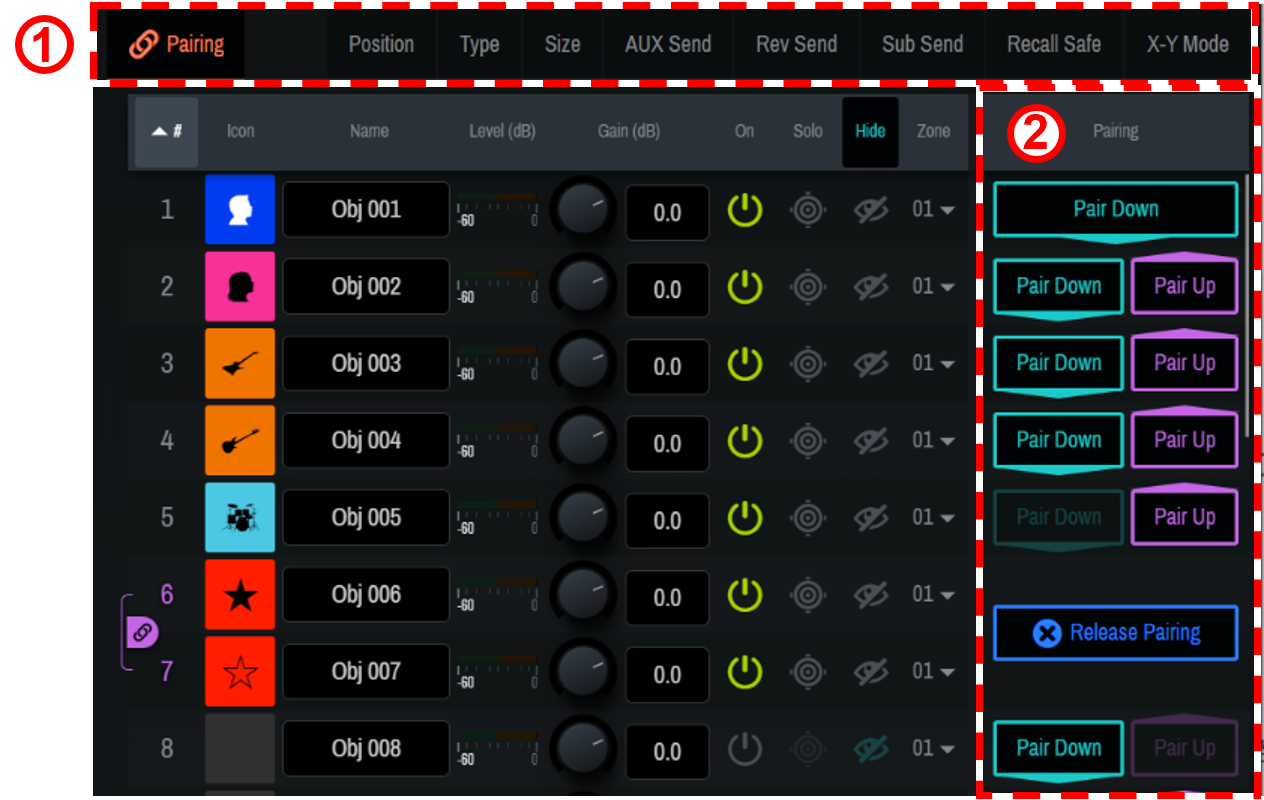
① When a parameter name is clicked, the selected function will be displayed to the right of the sound object list (② in the image).
| Depending on the Single Panel view or the software screen size, items other than the selected item may be displayed in the Controls window. |
-
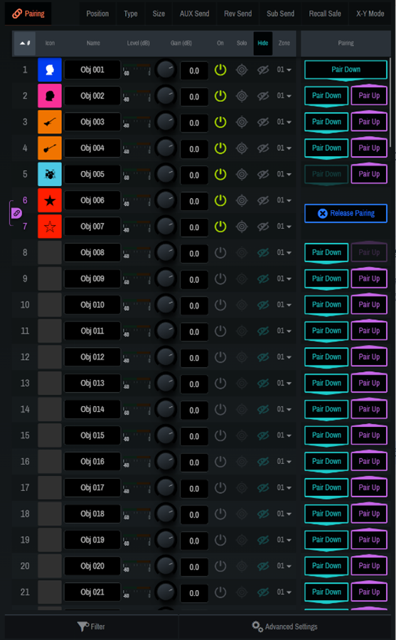
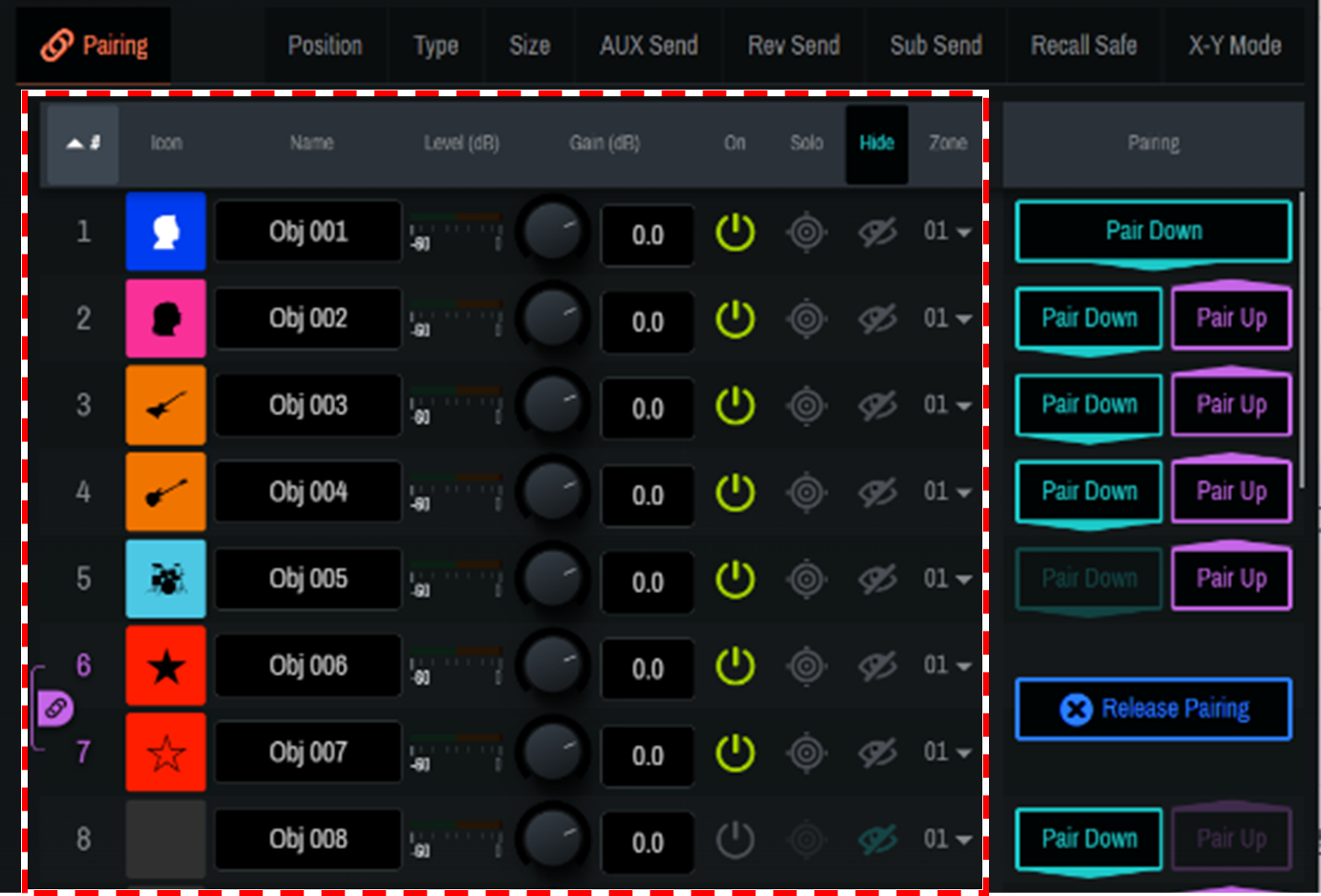
[Pairing]
The following parameters can be paired between two sound objects whose ID numbers are adjacent to each other.-
Gain, Solo, Hide, Position, Size, AUX Send, Rev Send, Recall Safe, Settings
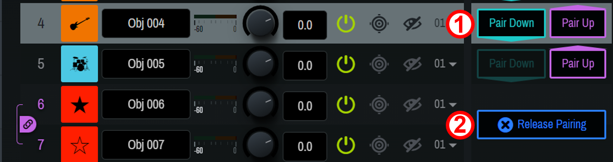
① [Pair Down] [Pair Up]
Adjacent sound objects will be paired.② [Release Pairing]
The pairing will be canceled.
-
-
[Position]
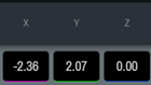 The position of the sound object will be displayed/set in X, Y, and Z coordinates. Set the coordinates between -500 (m) and 500 (m).
-
[Type]
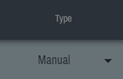 Select the method for controlling the coordinates of the sound object.
When a fingerprint mark " " is displayed for the sound object in the 2D Stage window, the object can be directly moved within the 2D Stage window.
Setting Explanation Manual
Allows for controlling the position of the sound object from AFC Image Controller or an external controller.
Static
Disables controlling the position of the sound object from AFC Image Controller or an external controller.
External
Allows for controlling the position of the sound object only from an external controller.
-
[Size]
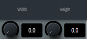 Set the width in the X-Y plane and the height in the Z axis direction of the sound object between 0.0 and 100.0. When the values are set to 100.0, audio will be output from all speakers in the zone to which the sound object is assigned.
-
[AUX Send]
 Set on/off and the send level of the AUX send.
-
[Rev Send]
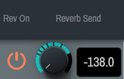 Set on/off and the send level of the reverb send. Audio after gain adjustment will be sent.
-
[Sub Send]
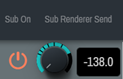 Set on/off and the send level of Sub Send. Audio of the selected sound object will be sent to [SubSpeakers] in [System]. Audio after gain adjustment will be sent.
-
[Recall Safe]

Recall Safe is a function that protects scene memories from being recalled. The Recall Safe settings are saved separately from scene data. Set on/off of the Recall Safe function. When the function is set to on, the parameter settings of sound objects will be retained when a scene is recalled. When the function is set to off, the scene will be recalled regardless of the parameter settings of the sound objects.
In addition, [Rec/S Params] allows you to set Recall Safe in detail for each item.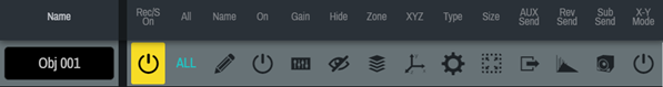
-
[X-Y Mode]
 Set the X-Y mode.
When the X-Y mode is set to on, the Z coordinate value of the sound object will be ignored, and rendering will be performed regardless of the Z coordinate of each speaker.
4.4. Scenes Window
You can name the current settings and save them as a "scene." Saved scenes can be recalled at any time.
The following information can be saved in a scene:
-
On/off and gain settings of sound objects
-
Display, position, size, icon, color, name, and type of sound objects
-
Level setting of Main (dB)
-
On/off and level setting of AUX Send
-
On/off and level setting of Rev Send
-
On/off and level setting of Sub Send
-
On/off setting of X-Y Mode
-
On/off setting of Hide
-
Zone settings
-
Reverb (Time, Space, and Equalizer) settings
| The [Pairing] setting is not included in the scenes. |
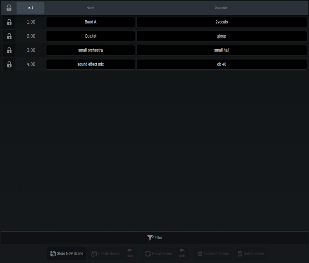
4.4.1. Registering a scene
Click [
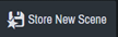 ] to open the dialog screen.
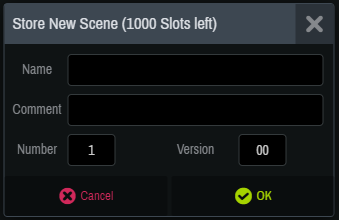
When registering a scene, you can enter the following information:
-
Name (Scene name) / Comment (Annotation) / Number (1 to 1000) / Version (0 to 99)
| Up to 1000 scenes can be registered. |
Once you have entered the information, click [OK] to register the scene. The registered scene will be reflected in the list. The Name and Comment (Annotation) of a registered scene can be edited from the Scene list. You can also narrow down the scenes displayed in the Scene list using [Filter].
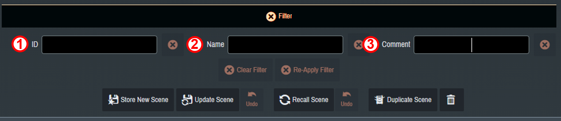
Multiple narrowing conditions can be selected.
① The scenes to be displayed are narrowed down to those meeting the condition entered in ID number.
② The scenes to be displayed are narrowed down to those meeting the condition entered in Name.
③ The scenes to be displayed are narrowed down to those meeting the condition entered in Comment.
4.4.2. Overwriting a scene
Overwrite an already registered scene with the current parameters.
Select the scene to be overwritten and click [
 Update Scene]. When the [
![]() ] mark has changed to [
] mark has changed to [
![]() ], click the button again to overwrite the scene.
], click the button again to overwrite the scene.
To cancel the overwrite, click the activated [
![]() Undo] button.
Undo] button.
|
If you click [
|
4.4.3. Recalling a scene
Select a scene from the Scene list and click [
 Recall Scene]. To cancel recalling the scene and return to the original state, click [
![]() Undo].
Undo].
4.4.4. Deleting a scene
Select the scene to be deleted from the Scene list, and then click [
 Delete Scene]. When the [Delete Scene] button turns orange, click it again to delete the scene.
| Once a scene is deleted, it cannot be restored. |
4.4.5. Duplicating a scene
Select the scene you want to duplicate and click [
 Duplicate Scene].
A dialog appears with only the Version value of the original scene updated. You can rewrite the information as desired and duplicate the scene.
| Note that if you enter a Number or Version value that already exists, the existing scene will be overwritten. |
4.5. Reverb Window
You can create the optimal reverberation based on the position of each sound object, and generate a reverb effect signals optimized for the position of each speaker.
This window offers multiple presets with different spatial shapes, and allows you to intuitively operate the temporal, spatial, and frequency parameters of the reverb components.
| Only one reverb pattern can be selected at a time. |
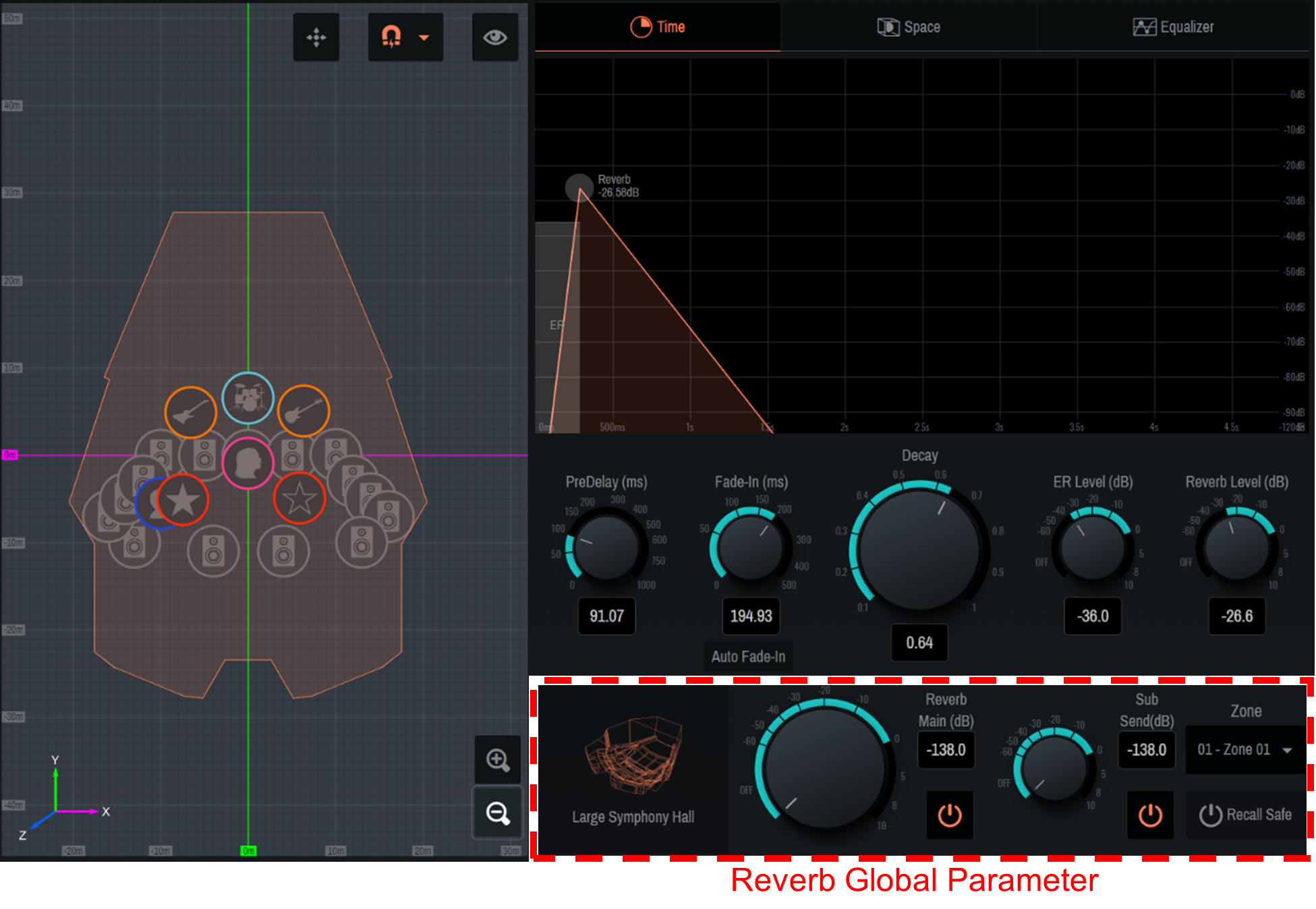
4.5.1. Reverb Global Parameter
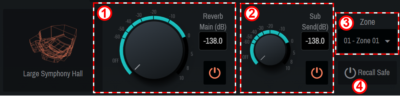
Adjust the overall output level of the reverb and determine the output zone.
①
[Reverb Main (dB)]
Adjust the overall output level of the reverb. Also, use "
![]() " to switch on/off.
" to switch on/off.
②
[Sub Send]
Adjust the level of the reverb to be output to the SubSpeakers. Also, use "
![]() " to switch on/off.
" to switch on/off.
③
[Zone]
Select the zone from which the reverb will be output.
④
[Recall Safe]
Set on/off of the Recall Safe function. If this item is on, no memory is recalled.
| Recall Safe is a function that protects scene memories from being recalled. The Recall Safe settings are saved separately from scene data. |
| To apply an edited reverb pattern to a different zone, we recommend using a scene. For the scene settings, refer to section 4.4 . |
4.5.2. Reverb pattern selection
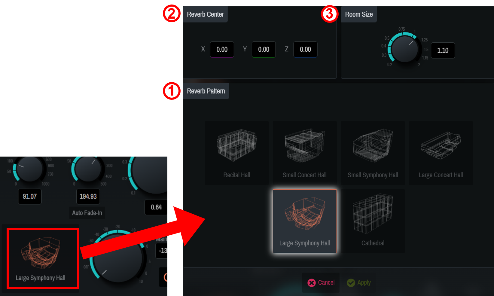
① Click the room icon, select a reverb pattern from six types, and adjust it. After selecting a pattern, set the following parameters.
②
[Reverb Center]
Set the center coordinates of the selected reverb pattern. Enter the coordinates directly, or drag the orange label in the 2D Stage window.
③
[Room Size]
Set the size (magnification) of the room for the selected pattern.
4.5.3. Time screen
The [Time] window allows you to set the temporal parameters of the reverbs.
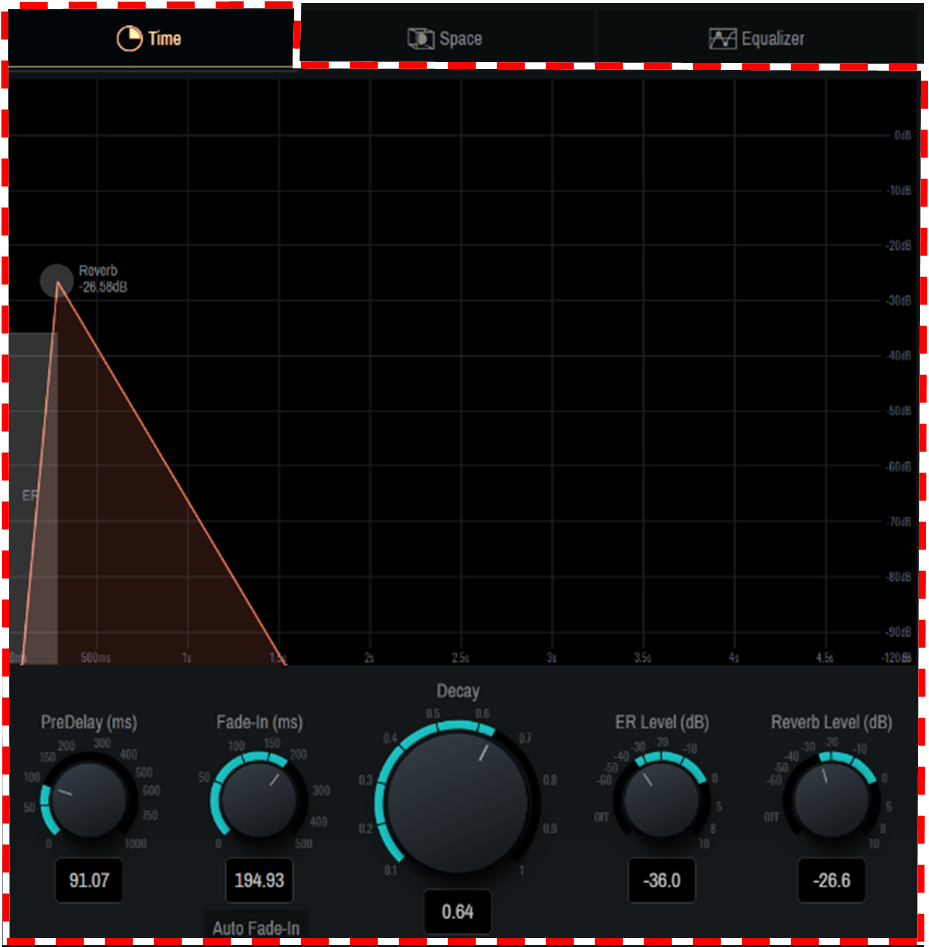
| Setting | Explanation |
|---|---|
|
Pre-Delay(ms) |
Adjusts the delay time before the reverb, including early reflections, takes effect. |
|
Fade In (ms) |
Adjusts Fade-in Time of the reverb. Turn on [Auto Fade-in] to adjust it automatically. |
|
Decay |
Adjusts the decay time of the reverb. |
|
ER Level(dB) |
Adjusts the early reflection level. |
|
Reverb Level(dB) |
Adjusts the reverb level. |
| You can also intuitively operate the displayed graph by dragging it. |
4.5.4. Space screen
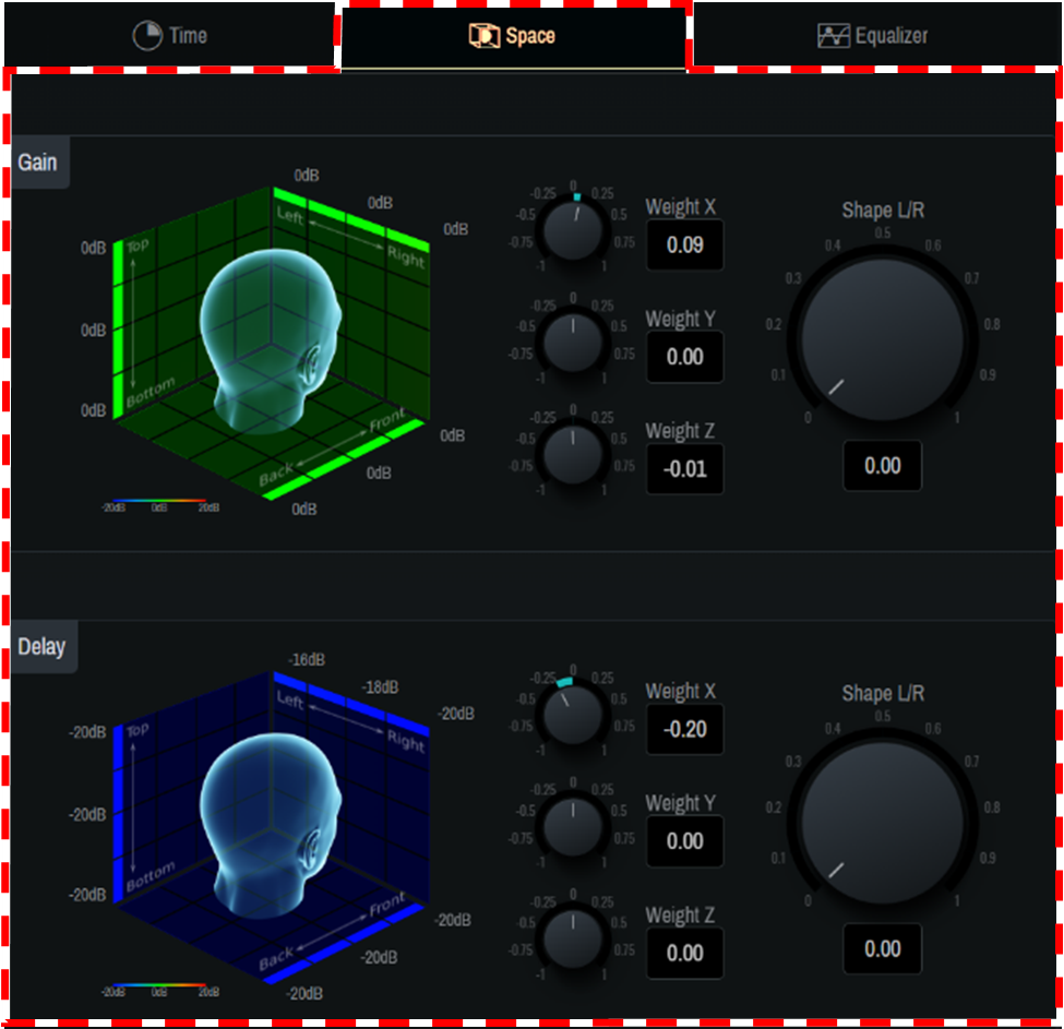
The [Space] window allows you to adjust the spatial characteristics of the 3D reverbs. The head image helps to intuitively understand the spatial changes of parameters centered around the human head facing in the positive Y-axis direction.
[Gain]
Adjust the gain bias for each axis of weight X, Y, and Z. In addition, the gain distribution in the center and sides in the X-axis direction can be adjusted using the Shape L/R knobs.
[Delay]
Adjust the delay bias for each axis of weight X, Y, and Z. In addition, the delay distribution in the center and sides in the X-axis direction can be adjusted using the Shape L/R knobs.
4.5.5. Equalizer screen
The [Equalizer] window allows you to adjust the frequency characteristics of the reverb using an eight-band EQ.
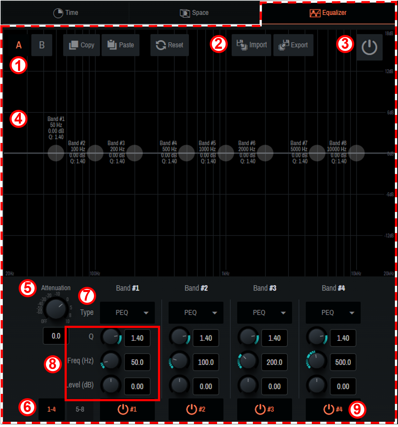
①
 [A] [B]
You can create two types of EQ, bank A and bank B.
The types can be switched freely, which allows you to compare them.
 [Copy] [Paste]
Copy and paste the created EQ.
 [Reset]
Reset the EQ of the selected bank.
②
 [Import] [Export]
The set EQ can be read/saved as a file.
-
When reading saved data
Click [Import], select the file to read in the pop-up window that appears, and click [Open].If the file cannot be read, the message "Failed to open the file" will be displayed. -
When saving the set data
Click [Export], enter a file name in the pop-up window that appears, and click [Save].If the file cannot be saved, the message "Failed to save the file" will be displayed.
③
![]() [Power Button]
[Power Button]
This button switches on/off of EQ.
④
EQ graph
The EQ for the currently selected bank will be displayed. You can also manipulate each band directly on the graph.
⑤
[Attenuation]
Adjust the attenuator.
⑥
[1-4] [5-8]
EQ bands will be switched.
⑦
[Type]
Select the EQ type from the ▼ button. The color of the frequency characteristic curve and part of the graph outer frame changes depending on the type.
⑧
[Q] [Freq(Hz)] [Level(dB)]
Set the parameters of the EQ selected in ⑦.
⑨
[
 Power button image]
On/off will be switched only for the EQ of the selected band.
4.6. System Window
Configure the output settings, such as Speakers, SubSpeakers, Zone, and AUX Out, as well as the settings for connections with external devices.
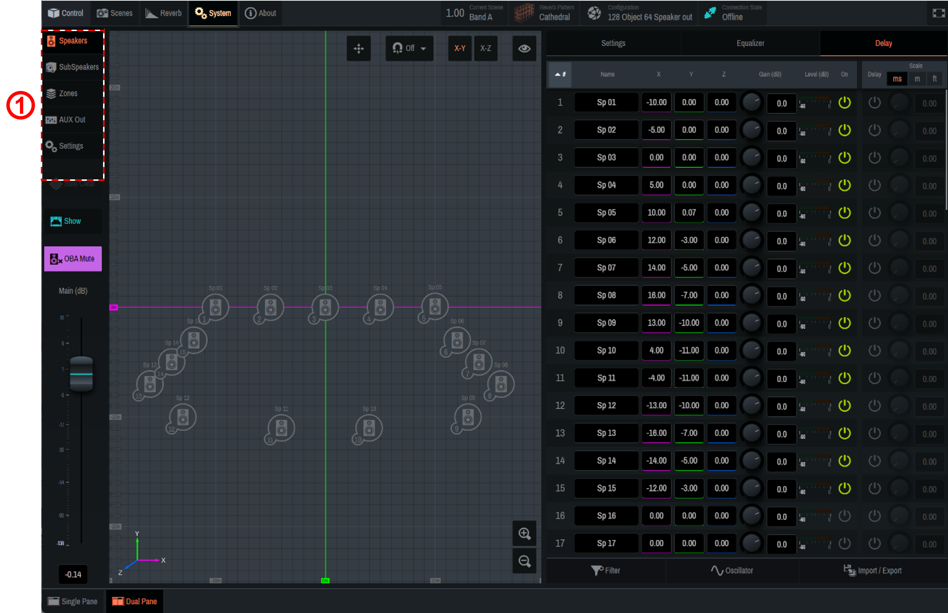
① Use the tabs to switch functions. When a tab is selected, each function will be displayed in the main window.
4.6.1. Speakers/SubSpeakers tab
-
Speakers/SubSpeakers parameter settings
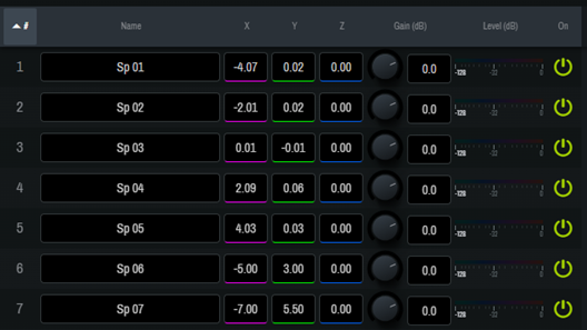
Setting Item (Settings) Overview #ID number
The ID number of each Speaker/SubSpeaker. Click # at the top to sort by ID number.
Name
Displays/allows you to edit the name of each Speaker/SubSpeaker. Click Name at the top to sort by name.
X, Y, Z
Displays/sets the position [m] of each Speaker/SubSpeaker. You can directly move the Speaker/SubSpeaker icons on the 2D Stage window.
Once the position is determined, click [✓ Apply] at the top of the window to confirm the change. To cancel the change, click [× Cancel].Gain(dB)
Adjusts the level of each Speaker/SubSpeaker.
Level(dB)
Displays the output level of each Speaker/SubSpeaker.
On
Sets on/off of each Speaker/SubSpeaker.
OSC
Outputs the noise set in [Oscillator].
-
Speaker/SubSpeaker parameter switching

① When a parameter is clicked, the selected function will be displayed to the right of the speaker list (② in the image).
Depending on the Single Panel view or the software screen size, items other than the selected item may be displayed in the Controls window. Setting Item (Settings) Overview Settings
Solo: The Solo on/off will be set for each Speaker/SubSpeaker. Click [Solo] at the top to turn all Speakers/SubSpeakers on/off at once. The Solo function is restricted in the Show mode.
Hide: The display of Speakers/SubSpeakers in the 2D Stage window will be set. Click [Hide] at the top to set the display of all Speakers/SubSpeakers at once.Equalizer
Sets EQ for each Speaker/SubSpeaker. To learn how to set EQ, refer to " 4.5.5 Equalizer screen ."
Delay
Sets the delay for each Speaker/SubSpeaker. The delay scale can be selected from three types.
-
Other settings
[Filter]
Narrow down the list items by ID number or Name. Multiple narrowing conditions can be selected.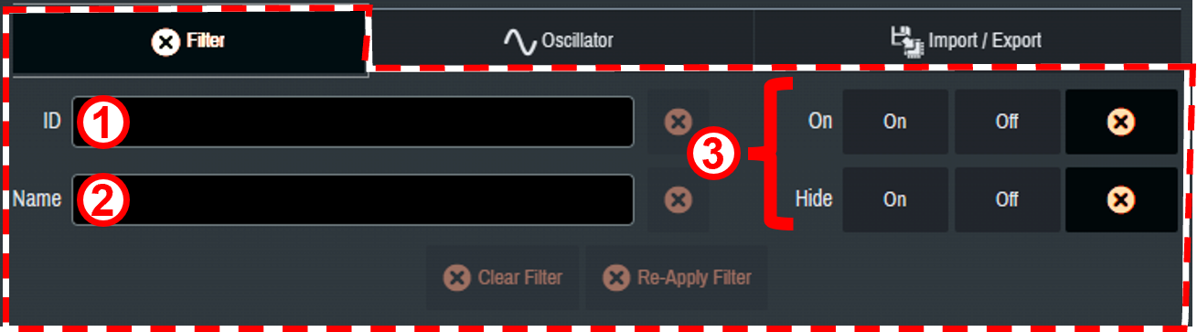
① The Speakers/SubSpeakers to be displayed are narrowed down to those meeting the condition entered in ID number.
② The Speakers/SubSpeakers to be displayed are narrowed down to those meeting the condition entered in Name.
③ The Speakers/SubSpeakers to be displayed are narrowed down based on On and on/off of Hide.[Oscillator]
This item allows you to select, edit, and output a sine wave or pink noise.The same setting is also applicable from Oscillator of AUX Out. 
① [Reference]
When this item is turned on, the oscillator signals will be output to Oscillator Reference Out.② [Level(dB)] knob
Set the output level.③ Oscillator mode selection
Select the mode from six types of waveforms.④ [Advanced settings window]
You can configure detailed settings when Pink, Burst, or Vari is selected.⑤ [Play button]
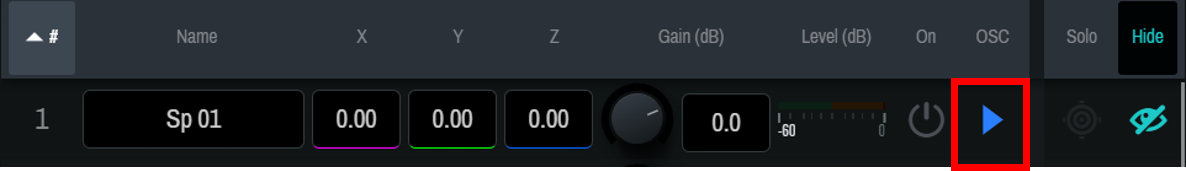
When this button in turned on, the oscillator signal output goes on standby. Press [ Play button] for each Speaker to output the signals.
[Import/Export]
Import or export speaker data.SubSpeakers do not have the import and export functions. 
① Import : Speaker position data in a ".nys" file will be imported.
② Export : Speaker position information will be exported as a.nys file.
The .nys file created with the NEXO NS-1 software can be imported into AFC Image Controller.
4.6.2. Zones tab
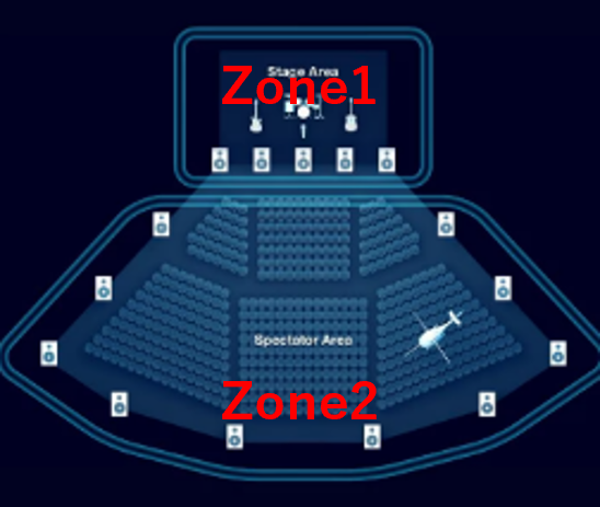
"Speaker zoning" is a function to assign the playback of a sound object only to a specific speaker group. You can create up to 32 speaker zones and assign multiple speakers to each speaker zone.
Each sound object is output only from the speakers in its assigned zone. Therefore, the range of sound object control is not limited even if speaker systems with different roles are mixed in the same space.
For example, zoning is possible in the way that sound objects on the stage are output only from the front speakers, and sound objects that move the sound image on the audience seat side are output only from the wall and ceiling speakers on the audience seat side.
Each speaker zone can also be set with a rendering area that converts panning in logical coordinates, such as those from an external DAW or mixing console, into any shape in real space.
| The RIVAGE series V7.0 and later support control. |
-
Assigning speakers to a zone
Click to select the speakers to be assigned to a zone. You can also edit the name of the zone.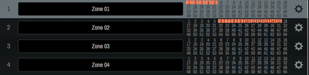
-
Zone settings
Click " " to configure detailed zone settings.
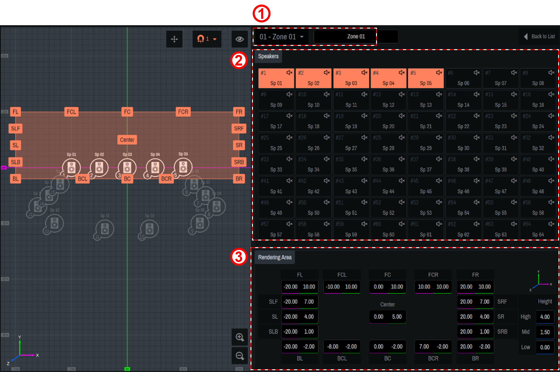
① [
 ]
]
Select a zone and edit the name of the zone.② [Speakers]
Select the speakers to assign to the zone.③ [Rendering Area]
Move the label icon on the 2D Stage or enter a numerical value to set the rendering area. For the Z-axis direction, enter the value in the Height field.-
Assign three or more speakers to the zone to be used for rendering.
-
Do not place all the speakers in a zone in a straight line.
-
If the X, Y, or Z coordinate of a sound object is controlled from AFC Image Controller or an external controller, the coordinate will not be converted into the rendering area.
About rendering areas
The rendering area settings are applied to the cases where the position information of sound objects is controlled with logical coordinates such as those of external DAW, the panner of a mixing console, or ADM-OSC.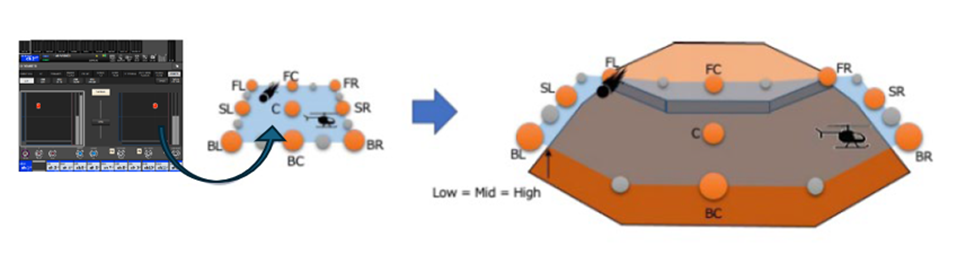
-
4.6.3. AUX Out tab
Configure the AUX Out settings.

①
[
![]() Power button]
Power button]
This button allows you to turn on/off the AUX Out output.
②
[PRE] [POST] switch buttons
These buttons allow you to switch sending of signals to the AUX bus of a sound object between PRE and POST.
③
[AUX Out(dB)]
Adjust the output level of AUX Out.
④
[HiPass]
Set the high-pass filter. The filter type can be selected from the ▼ button.
⑤
[LoPass]
Set the low-pass filter. The filter type can be selected from the ▼ button.
⑥
[▶ Oscillator]
The specified oscillator signals will be sent to AUX Out.
⑦
[Oscillator]
This item allows you to select, edit, and output a sine wave or pink noise. For operation instructions, refer to
4.6.1. Speakers/SubSpeakers tab
.
4.6.4. Settings tab
Save project files you have created and set synchronization between the DME and the computer.
For the DME, you need to set a configuration in which AFC Image components are placed beforehand using ProVisionaire Design. To learn how to set the configuration, refer to
3. Basic Usage
.
①
"Sync" area
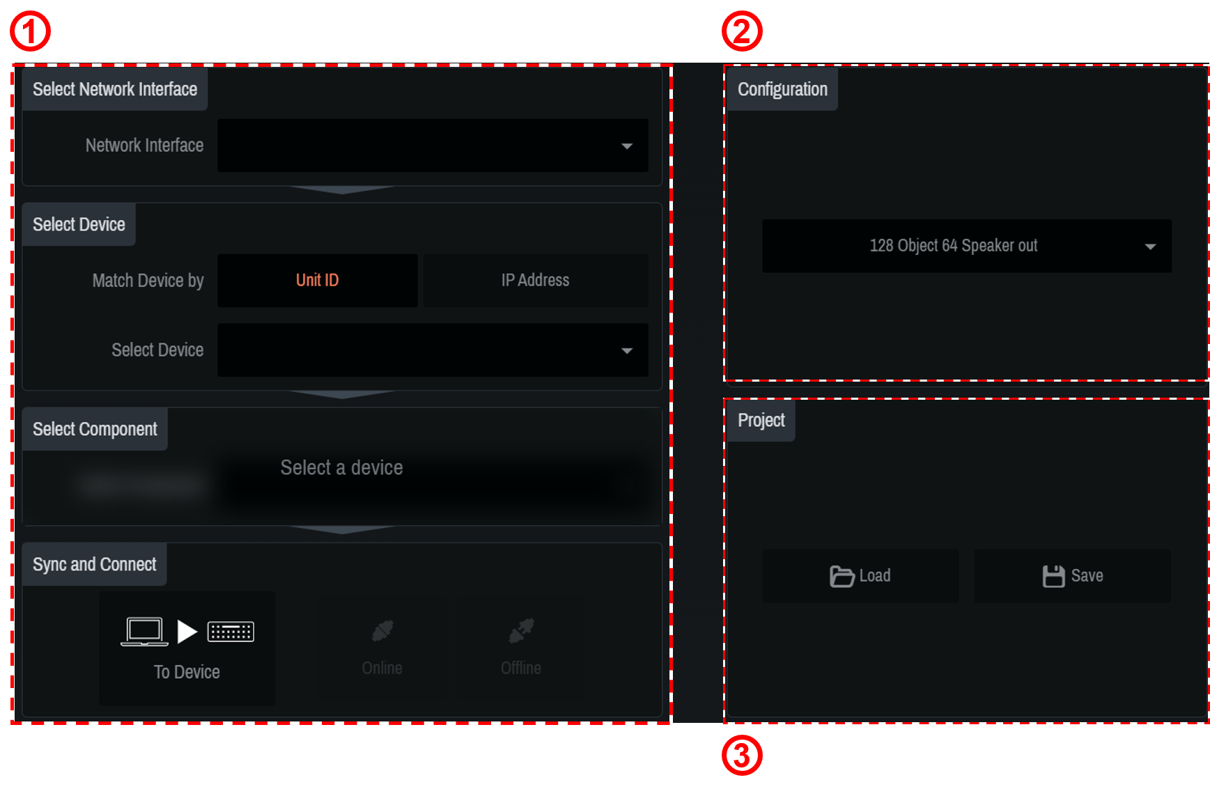
Connect the DME and computer and synchronize them for using AFC Image Controller to control the DME.
| The state in which the DME and AFC Image Controller operate in synchronization is called the "online state." Also, the operation to achieve this state is called "synchronization." |
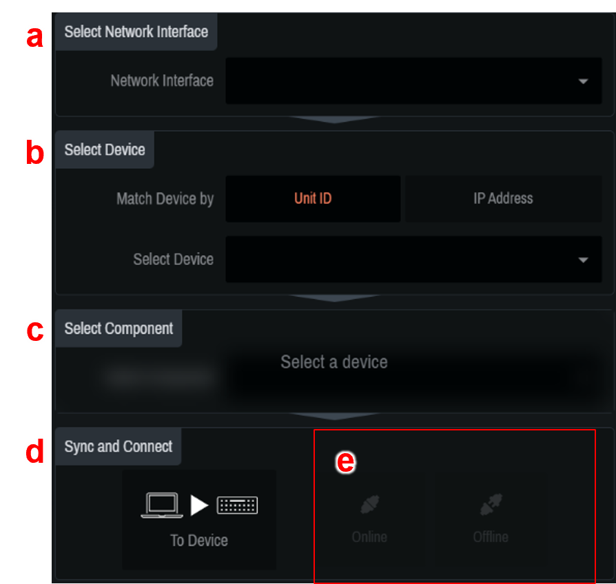
-
[Select Network Interface]
Select the network interface to be used by the computer from the list. Set the IP addresses of the network interface and DME to be used so that they are on the same network.For the DME network settings, refer to the DME7/DME10 Reference Manual. -
[Select Device]
Select the DME to be connected. To search for DMEs on the same network, select Unit ID or IP Address from [Match Device by].-
For Unit ID: Select the DME to be connected from the list.
-
For IP Address: Enter the IP Address and press the Find button. Information about the found device will be displayed. If the device is not found, the error message "Unable to find device at [entered IP Address]" will be displayed.
The indicator shows the synchronization status with the DME.
Green: Offline state
White: Lost state
The lost state means that the device you want to connect to cannot be found due to factors such as the device being turned off.
Blue: Online state.
Yellow: Incompatible state
-
-
[Select Component]
Select the component ID of the AFC Image component set in ProVisionaire Design.
If there are multiple AFC Image components, select the target component. -
[Sync and Connect]
Select the method for synchronizing the DME and AFC Image Controller.
To Device: The AFC Image Controller settings will be sent to the DME and will overwrite its settings.
From Device: The DME settings will be read into AFC Image Controller.When connecting from multiple computers at the same time, you can select To Device only for the computer that is first connected and synchronized with the DME.
For the second or subsequent computers, only "From Device" can be selected. -
Select Online. (If the conditions are not met, the button will not be displayed.)
If a PIN code is specified when the AFC Image components are placed using ProVisionaire Design, enter the specified PIN code in the window that appears.
If the incorrect PIN code is entered, the message "Component Access PIN is incorrect."is displayed.
To learn how to set the PIN code, refer to 2.1.1 .
②
"Configuration" area
Select the configuration of the DME to be connected.

| When changing the configuration, you may lose parameter settings. |
③
"Project" area
Save or read the created projects.
-
[Load]
Double-click the saved.afciprj file to launch this software and load the project file.
In the dialog that appears after the click operation, select the file to read.If the file cannot be read, the message "Failed to open the file" will be displayed. -
[Save]
Save the current state as a project file.
In the dialog that appears after the click operation, name the current settings and save them.If the file cannot be saved, the message "Failed to save the file" will be displayed.
4.7. About Window
You can check the current version information and various license information.