Effect
Effect
There are two categories of dspMixFx effects, based on their intended use.
1. Standard Effect
These effects are suitable for general purposes such as music production and instrument performance. They are categorized as follows in each area of the Main Window.
Channel Effect
・
Sweet Spot Morphing Channel Strip
・
Guitar Amp Classics (Clean, Crunch, Lead, Drive)
・
PITCH FIX
REV-X Area Effect
・
REV-X (Hall, Room, Plate)
・
Delay
2. Streaming Effect
These effects are applied to the streaming mix. They are categorized as follows in each area of the Main Window.
Channel Effect
・
GATE
・
COMPRESSOR
DAW/Music/Voice Effect
・
DUCKER
Main Area Effect
・
MULTI-BAND COMPRESSOR
Sweet Spot Morphing Channel Strip
The Sweet Spot Morphing Channel Strip (“Channel Strip” for short) is a multi-effect that combines compression and EQ. Advanced sound engineering know-how is condensed into a number of convenient presets that can be simply and instantly recalled, for professional results.
Six channel strips are provided, and each can be assigned to the monitor sound only, or to both the monitor and recorded sound.
The Channel Strip equipped with the device and the Channel Strip of the VST Plug-in version have the same parameters. When using the Channel Strip on Cubase series programs, you can share the settings between the built-in Channel Strip and the Channel Strip of the VST Plug-in version as a preset file.
Also, when assigning the Channel Strip of the VST Plug-in version to the effect slot on Cubase series programs, select it from the [Dynamics] category (in the case of the default settings).
For more information about the VST Plug-in version, refer to the “Basic FX Suite Operation Manual.”
How to Open the Window
・
From dspMixFx UR-C
Select the “Channel Strip” from the “Effect Type”, then click “Channel Strip Edit” in the section “Channel Area.”
・
From Dedicated Windows for Cubase Series
Select the “Channel Strip” from the “Effect Type”, then click “Channel Strip Edit” in the section “Input Settings Window.”
[Common to Compressor and Equalizer]
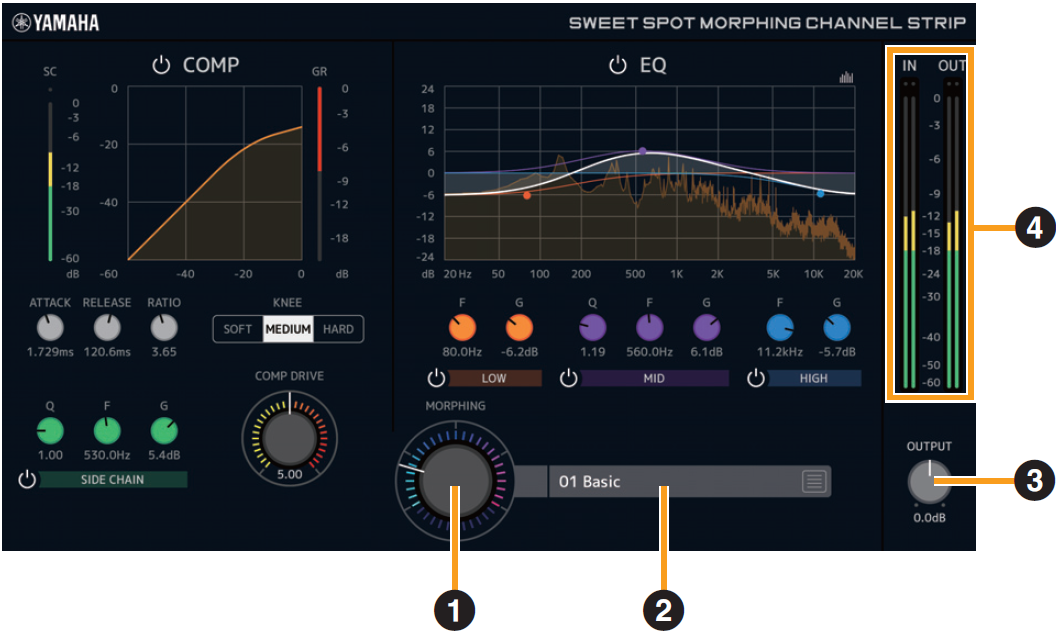
- ➊ MORPHING
-
Adjusts the parameter of the Sweet Spot Data.
You can simultaneously adjust the compressor and equalizer settings which are set to five points around this knob by turning this knob. When you set the knob between two adjacent points, the compressor and equalizer settings will be set to an intermediate value. - ➋ Sweet Spot Data
-
Selects the Sweet Spot Data.
- ➌ OUTPUT
-
Adjusts the total gain of the Channel Strip.
Range : −18.0 dB–+18.0 dB - ➍ Level Meters
-
Indicates the input and output levels of the Channel Strip.
[Compressor]
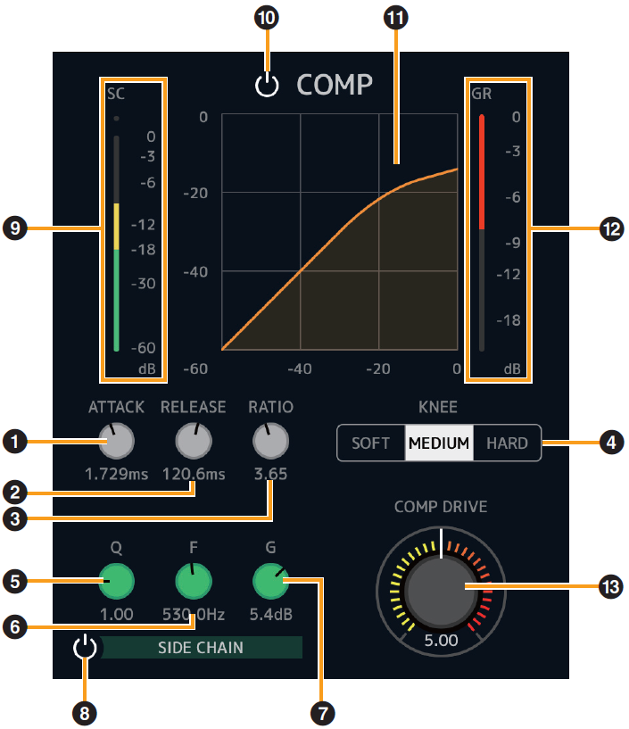
- ➊ ATTACK
-
Adjusts the attack time of the compressor.
Range : 0.092 msec–80.00 msec - ➋ RELEASE
-
Adjusts the release time of the compressor.
Range : 9.3 msec–999.0 msec - ➌ RATIO
-
Adjusts the ratio of the compressor.
Range : 1.00–∞ - ➍ KNEE
-
Selects the knee type of the compressor.
| Options | Description |
|---|---|
|
SOFT |
Produces the most gradual change. |
|
MEDIUM |
Results in a setting midway between SOFT and HARD. |
|
HARD |
Produces the sharpest change. |
- ➎ SIDE CHAIN Q
-
Adjusts the band width of the side chain filter.
Range : 0.50–16.00 - ➏ SIDE CHAIN F
-
Adjusts the center frequency of the side chain filter.
Range : 20.0 Hz–20.0 kHz - ➐ SIDE CHAIN G
-
Adjusts the gain of the side chain filter.
Range : −18.0 dB–+18.0 dB - ➑ SIDE CHAIN On/Off
-
Turns the side chain on (lit) and off (unlit).
- ➒ SC Meter
-
Indicates the trigger signal level for the side chain.
- ➓ COMPRESSOR On/Off
-
Turns the compressor on (lit) and off (unlit).
- ⓫ Compressor Curve
-
This graph indicates the approximate compressor response. The vertical axis indicates the output signal level, and the horizontal axis indicates the input signal level.
- ⓬ Gain Reduction Meter
-
Indicates the gain reduction.
- ⓭ COMP DRIVE
-
Adjusts the degree to which the compressor is applied. The higher the value, the greater the effect.
Range : 0.00–10.00
[Equalizer]
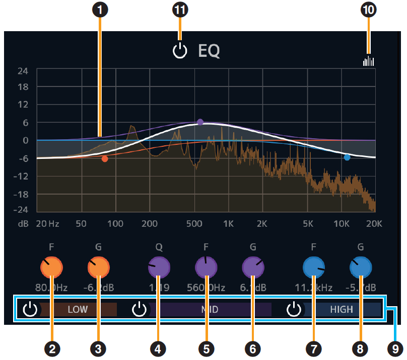
- ➊ Equalizer Curve
-
This graph indicates the characteristics of the 3-band equalizer.
The vertical axis indicates the gain, and the horizontal axis indicates the frequency. You can adjust LOW, MID, and HIGH by dragging each handle in the graph. - ➋ LOW F
-
Adjusts the center frequency of the low band.
Range : 20.0 Hz–1.00 kHz - ➌ LOW G
-
Adjusts the gain of the low band.
Range : −18.0 dB–+18.0 dB - ➍ MID Q
-
Adjusts the band width of the middle band.
Range : 0.50–16.00 - ➎ MID F
-
Adjusts the center frequency of the middle band.
Range : 20.0 Hz–20.0 kHz - ➏ MID G
-
Adjusts the gain of the middle band.
Range : −18.0 dB–+18.0 dB - ➐ HIGH F
-
Adjusts the center frequency of the high band.
Range : 500.0 Hz–20.0 kHz - ➑ HIGH G
-
Adjusts the gain of the high band.
Range : −18.0 dB–+18.0 dB - ➒ EQ Band On/Off
-
Turns each EQ band on (lit) and off (unlit) individually.
- ➓ Spectrum Display On/Off
-
Turns the Spectrum Display of the Equalizer Curve on (lit) and off (unlit).
- ⓫ EQ On/Off
-
Turns the equalizer on (lit) and off (unlit).
If you are using Sweet Spot Morphing Channel Strip V1.2.5 or earlier
Added the Preset Converter window to convert Presets made by Sweet Spot Morphing Channel Strip V1.2.5 or earlier to be compatible with V1.5.0 or later.
The Preset Converter window automatically appears when opening the Sweet Spot Morphing Channel Strip. If you want to prevent it from appearing, check “Don’t ask me again” and will not open the next time.
If the Preset Converter does not appear automatically or if you want to display it manually, click the logo in the upper right corner of the Sweet Spot Morphing Channel Strip window.
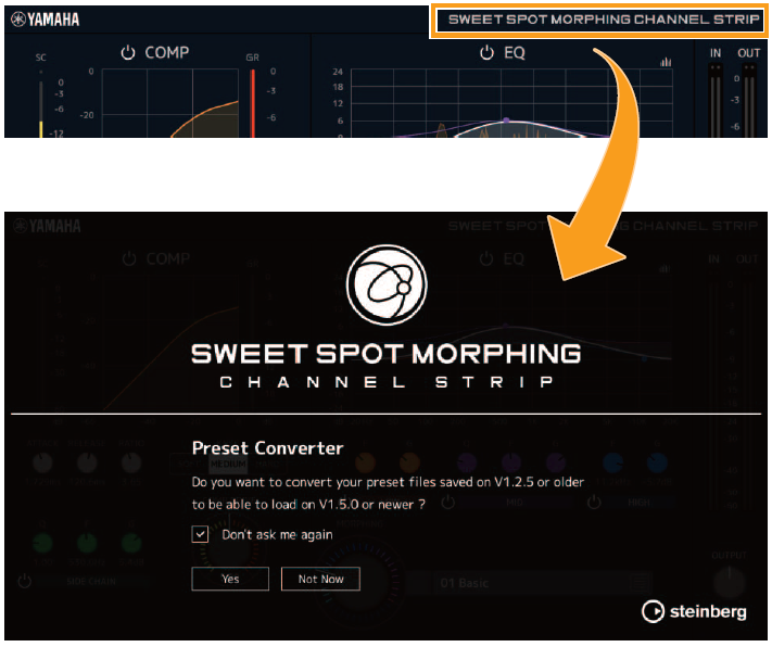
Click the “Yes” button to enable use of Presets saved in previous versions.
Click the “Not Now” button to open the plug-in without converting the previous Presets.
NOTICE
* Presets created by V1.5.0 or later are not compatible with V1.2.5 or earlier.
* When V1.5.0 or later has been installed to the computer that was using V1.2.5 or earlier, the Mono version of the V1.2.5 or earlier will remain. If you open a project file with V1.2.5 or earlier in this state, the plug-in V1.2.5 or earlier will be loaded to the channel to which the Mono version has been assigned. If you want to replace it to one of V1.5.0 or later, re-select the appropriate channel plug-ins to V1.5.0 or later.
Guitar Amp Classics
Guitar Amp Classics are guitar amp simulations that make extensive use of advanced Yamaha modeling technology.
Four amp types with different sonic characteristics are provided.
The Guitar Amp Classics equipped with the device and the Guitar Amp Classics of the VST Plug-in version have the same parameters. When using the Guitar Amp Classics on Cubase series programs, you can share the settings between the built-in Guitar Amp Classics and the Guitar Amp Classics of the VST Plug-in version as a preset file. Also, when assigning the Guitar Amp Classics of the VST Plug-in version to the effect slot on Cubase series programs, select it from the [Distortion] category (in the case of the default settings). Note that Guitar Amp Classics equipped with the device cannot be used when the sample rate is set to 176.4 kHz or 192 kHz.
For more information about the VST Plug-in version, refer to the “Basic FX Suite Operation Manual.”
How to Open the Window
・
From dspMixFx UR-C
Select the “Guitar Amp Classics” from the “Effect Type”, then click “Effect Edit” in the section “Channel Area.”
・
From Dedicated Windows for Cubase Series
Select the “Guitar Amp Classics” from the “Effect Type”, then click “Effect Edit” in the section “Input Settings Window.”
CLEAN
This amp type is optimized for clean tones, effectively simulating the tight brilliance of transistor amplifiers. The tonal character of this amp model provides an ideal platform for recording with multi-effects. It also features built-in chorus and vibrato effects.
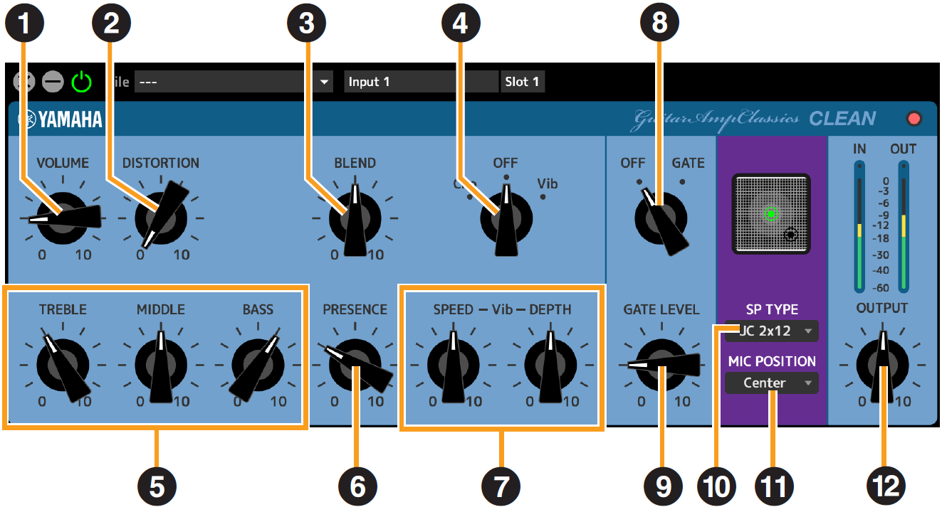
- ➊ VOLUME
-
Adjusts the amplifier’s input level.
- ➋ DISTORTION
-
Adjusts the depth of distortion produced.
- ➌ BLEND
-
Adjusts the balance between the direct and effect sound.
- ➍ Cho/OFF/Vib
-
Turns the Chorus or Vibrato effect on or off. Set to [Cho] to turn the Chorus effect on, or to [Vib] to turn the Vibrato effect on.
- ➎ TREBLE/MIDDLE/BASS
-
These three controls adjusts the amplifier’s tonal response in the high, middle, and low frequency ranges.
- ➏ PRESENCE
-
Can be adjusted to emphasize the high frequencies and overtones.
- ➐ SPEED/DEPTH
-
These controls adjust the speed and depth of the Vibrato effect when it is on.
The SPEED and DEPTH controls only work with the Vibrato effect, and are disengaged when the Cho/OFF/Vib control, above, is set to “Cho” or “OFF.” - ➑ OFF/GATE
-
Turns the noise gate on and off.
- ➒ GATE LEVEL
-
Adjusts the gate level.
- ➓ SP TYPE
-
Selects the type of cabinet.
For more information about the characteristics of each type, refer to the Guitar Amp Classics Reference section “ Cabinet types and characteristics .”
Type and configuration : BS 4×12", AC 2×12", AC 1×12", AC 4×10", BC 2×12", AM 4×12", YC 4×12", JC 2×12" - ⓫ MIC POSITION
-
Selects the position of the virtual microphone for placement in front of the cabinet. You can also select the microphone position by clicking on the speaker image.
| Position | Description |
|---|---|
|
Center |
Microphone placement aiming at the center of the speaker cone. |
|
Edge |
Microphone placement aiming at the edge of the speaker cone. |
- ⓬ OUTPUT
-
Adjusts the final output level.
CRUNCH
This is the amp type to use when you want lightly overdriven crunch tones. The CRUNCH model simulates the type of vintage tube amplifiers that are favored for blues, rock, soul, R&B, and similar styles.

- ➊ Normal/Bright
-
Selects a normal or bright tonal character. The [Bright] setting emphasizes the high-frequency overtones.
- ➋ GAIN
-
Adjusts the input level applied to the preamp stage. Rotate clockwise to increase the amount of overdrive produced.
- ➌ TREBLE/MIDDLE/BASS
-
These three controls adjust the amplifier’s tonal response in the high, middle, and low frequency ranges.
- ➍ PRESENCE
-
Can be adjusted to emphasize the high frequencies and overtones.
- ➎ OFF/GATE
-
Turns the noise gate on and off.
- ➏ GATE LEVEL
-
Adjusts the gate level.
- ➐ SP TYPE
-
Selects the type of cabinet.
For more information about the characteristics of each type, refer to the Guitar Amp Classics Reference section “ Cabinet types and characteristics .”
Type and configuration : BS 4×12", AC 2×12", AC 1×12", AC 4×10", BC 2×12", AM 4×12", YC 4×12", JC 2×12" - ➑ MIC POSITION
-
Selects the position of the virtual microphone for placement in front of the cabinet. You can also select the microphone position by clicking on the speaker image.
| Position | Description |
|---|---|
|
Center |
Microphone placement aiming at the center of the speaker cone. |
|
Edge |
Microphone placement aiming at the edge of the speaker cone. |
- ➒ OUTPUT
-
Adjusts the final output level.
DRIVE
The DRIVE amp type provides a selection of distortion sounds that simulate the tonal character of various highgain tube amplifiers. From mildly overdriven crunch to heavy distortion suitable for hard rock, heavy metal, or hardcore styles, this model offers a wide range of sonic capabilities.
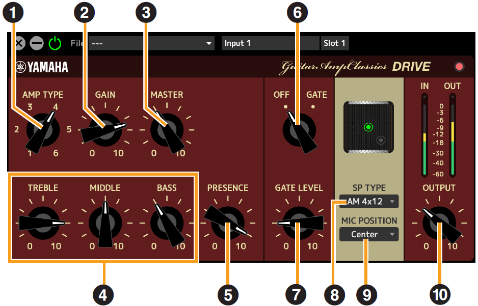
- ➊ AMP TYPE
-
Six amplifier types are provided.
Types 1 and 2 feature relatively mild distortion that allows picking nuances to come through naturally. Types 3 and 4 have more pronounced overtones, resulting in a fat, soft tone. Types 5 and 6 deliver wilder, aggressive distortion with a tight attack.
The even-numbered amp types have greater presence and range than the odd-numbered types. - ➋ GAIN
-
Adjusts the input level applied to the preamp stage. Rotate clockwise to increase the amount of distortion produced.
- ➌ MASTER
-
Adjusts the output level from the preamp stage.
- ➍ TREBLE/MIDDLE/BASS
-
These three controls adjust the amplifier’s tonal response in the high, middle, and low frequency ranges.
- ➎ PRESENCE
-
Can be adjusted to emphasize the high frequencies and overtones.
- ➏ OFF/GATE
-
Turns the noise gate on and off.
- ➐ GATE LEVEL
-
Adjusts the gate level.
- ➑ SP TYPE
-
Selects the type of cabinet.
For more information about the characteristics of each type, refer to the Guitar Amp Classics Reference section “ Cabinet types and characteristics .”
Type and configuration : BS 4×12", AC 2×12", AC 1×12", AC 4×10", BC 2×12", AM 4×12", YC 4×12", JC 2×12"
- ➒ MIC POSITION
-
Selects the position of the virtual microphone for placement in front of the cabinet. You can also select the microphone position by clicking on the speaker image.
| Position | Description |
|---|---|
|
Center |
Microphone placement aiming at the center of the speaker cone. |
|
Edge |
Microphone placement aiming at the edge of the speaker cone. |
- ➓ OUTPUT
-
Adjusts the final output level.
LEAD
The LEAD amp type simulates a high-gain tube amp that is rich in overtones. It is ideally suited to playing lead guitar lines that will project well in an ensemble, but it can also be set up for crisp accompaniment tones as well.
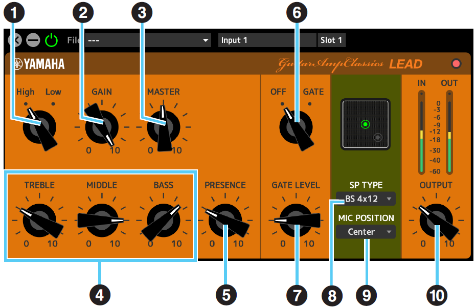
- ➊ High/Low
-
Selects the amp output type. The [High] setting simulates a high-output amp, and allows the creation of more distorted tones.
- ➋ GAIN
-
Adjusts the input level applied to the preamp stage. Rotate clockwise to increase the amount of distortion produced.
- ➌ MASTER
-
Adjusts the output level from the preamp stage.
- ➍ TREBLE/MIDDLE/BASS
-
These three controls adjust the amplifier’s tonal response in the high, middle, and low frequency ranges.
- ➎ PRESENCE
-
Used to emphasize the high frequencies and overtones.
- ➏ OFF/GATE
-
Turns the noise gate on and off.
- ➐ GATE LEVEL
-
Adjusts the gate level.
- ➑ SP TYPE
-
Selects the type of cabinet.
For more information about the characteristics of each type, refer to the Guitar Amp Classics Reference section “ Cabinet types and characteristics .”
Type and configuration : BS 4×12", AC 2×12", AC 1×12", AC 4×10", BC 2×12", AM 4×12", YC 4×12", JC 2×12"
- ➒ MIC POSITION
-
Selects the position of the virtual microphone for placement in front of the cabinet. You can also select the microphone position by clicking on the speaker image.
| Position | Description |
|---|---|
|
Center |
Microphone placement aiming at the center of the speaker cone. |
|
Edge |
Microphone placement aiming at the edge of the speaker cone. |
- ➓ OUTPUT
-
Adjusts the final output level.
Guitar Amp Classics Reference
Using the GAIN, MASTER, and OUTPUT Controls
The tonal character of the DRIVE and LEAD amp types can be adjusted over a wide range via the GAIN, MASTER, and OUTPUT controls.
GAIN adjusts the level of the signal applied to the preamp stage, affecting the amount of distortion produced. MASTER adjusts the output level from the preamp stage that is then fed to power amp stage. The GAIN and MASTER control settings have a large effect on the final sound, and the MASTER control may need to be turned up fairly high in order to drive the power stage sufficiently for optimum tone.The OUTPUT control adjusts the final output level from the amp model without affecting the distortion or tone, and is useful for adjusting the guitar’s volume without changing any other aspects of the sound.
Cabinet types and characteristics
The following table shows the cabinet characteristics that are common to each of the four types:
CLEAN
,
CRUNCH
,
DRIVE
, and
LEAD
.
| SP TYPE | Characteristics | Speaker configuration |
|---|---|---|
|
BS 4×12 |
British flat stack type with rich cabinet resonance. |
4×12" |
|
AC 2×12 |
American combo type cabinet, featuring a clear tone for versatile use in various music genres. |
2×12" |
|
AC 1×12 |
American combo type cabinet, featuring a clear tone for ensemble use. |
1×12" |
|
AC 4×10 |
American combo type cabinet, featuring a bright tone reminiscent of more traditional guitar sounds. |
4×10" |
|
BC 2×12 |
British combo type cabinet, ideal for distortion sounds and featuring a wide range with broad treble response. |
2×12" |
|
AM 4×12 |
American stack type cabinet, ideal for matching with high-power amplifiers and featuring a clear sound contour. |
4×12" |
|
YC 4×12 |
Yamaha F series combo type cabinet, featuring a rich midrange and a mild high range. |
4×12" |
|
JC 2×12 |
Japanese combo type cabinet, ideal for clean sounds, and featuring a rich mid-high range plus modulation effects. |
2×12" |
PITCH FIX
Adjusts the pitch and formant, and processes the microphone sound. It can also correct to a specified pitch.
This unit has one Pitch Fix available. Sampling frequencies of 44.1 kHz or 48 kHz can be used. This cannot be used for channels with Channel Link turned on.
How to Open the Screen
・
From dspMixFx UR-C
In the MIX area, after selecting Pitch Fix from “Effect Type” in the channel area, click “Edit effect.”
・
From Dedicated Windows for Cubase Series
Select Pitch Fix from “Effect Type” in the effect setting area.Click “Edit effect” to start dspMixFx UR-C, and the dspMixFx UR-C PITCH FIX screen will open.
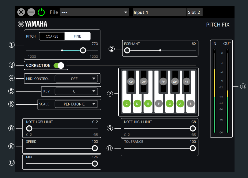
- ➊ PITCH
-
Adjusts the pitch within a range of one octave up or down. Select the pitch adjustment unit from COARSE (semitones) or FINE (cents).
When COARSE is selected : −12–+12 (semitones)
When FINE is selected : −1200–+1200 (cents) - ➋ FORMANT
-
Adjusts the formants.
A low value gives a deeper voice quality, and a high value gives a higher voice quality.
Range : −62–+62 - ➌ CORRECTION
-
Turns the function to correct to the specified scale ON/OFF. When CORRECTION is OFF, parameters ➍ and after are unavailable.
- ➍ MIDI CONTROL
-
Uses MIDI note messages to set the scale correction. It supports both the MIDI IN connector on the main unit and USB MIDI.
| Setting | Description |
|---|---|
|
OFF |
The MIDI setting function is disabled. |
|
SETTING |
In this setting, ➏ SCALE can be set to CUSTOM or anything other than CHROMATIC. If CHROMATIC is selected as SCALE already, it will be changed to CUSTOM.
|
|
REAL TIME |
Specifies the scale correction in real time using Note On/Off. In this setting, ➏ SCALE can be set to CUSTOM or SINGLE. If something other than SINGLE is selected as SCALE already, it will be changed to CUSTOM.
|
- ➎ KEY / ➏ SCALE
-
Selects Key and Scale to specify the scale to be corrected. The specified scale is reflected in the ➐ Keyboard buttons.
KEY Range : C, C#, D, …, A#, B
SCALE Setting : CUSTOM, SINGLE, MAJOR, NATURAL MINOR, HARMONIC MINOR, MELODIC MINOR, PENTATONIC, CHROMATIC - ➐ Keyboard buttons
-
The selected ➎ KEY and ➏ SCALE are displayed. You can select the sound to be corrected by operating the Keyboard buttons (SCALE will change to CUSTOM). When ➍ MIDI CONTROL is set to SETTING or REAL TIME, the Keyboard buttons cannot be operated.
- ➑ NOTE LOW LIMIT / ➒ NOTE HIGH LIMIT
-
Specifies the upper and lower limits of the input pitch to be corrected. (For example, if you want to always correct the scale from C3 to B3 even if the octave of the input sound is different, set NOTE LOW LIMIT to C3 and NOTE HIGH LIMIT to B3.)
Range : C−2, C#−2, …, F#8, G8NOTE
Pitch correction is only enabled when at least one key on the keyboard within the specified pitch range is played.For example, if NOTE LOW LIMIT is set to C3 and NOTE HIGH LIMIT is set to E3, pitch correction is not applied if only the F key is played on the keyboard. - ➓ SPEED
-
Sets the speed at which the input sound is corrected to the target scale.
Range : 0–100 - ⓫ TOLERANCE
-
Sets the sensitivity to pitch changes.
Range : 0–100 - ⓬ MIX
-
Adjusts the volume balance before and after scale correction. The higher the value, the louder the volume after scale correction.
Range : 0–126 - ⓭ Level Meter
-
Displays the signal level. The Peak Hold is always ON.
| Display Color | Description |
|---|---|
|
Green |
Up to −18 dB |
|
Yellow |
Up to 0 dB |
|
Red |
If Clipped |
REV-X
REV-X is a digital reverb platform developed by Yamaha for pro audio applications.
One REV-X effect is included in this unit. Input signals can be sent to the REV-X effect, and the REV-X effect is applied only to the monitor outputs. Three types of REV-X are available: Hall, Room, and Plate.
The hardware REV-X equipped with the device and REV-X of the VST Plug-in version have essentially the same parameters. However, the [OUTPUT] and [MIX] parameters are only available in the VST Plug-in version.When using REV-X on Cubase series programs, you can share the settings between the built-in REV-X and REV-X of the VST Plug-in version as a preset file. Also, when assigning REV-X of the VST Plug-in version to the effect slot on Cubase series programs, select it from the [Reverb] category (in the case of the default settings).
For more information about the VST Plug-in version, refer to the “Basic FX Suite Operation Manual.”
The built-in REV-X is equipped with an “FX Bus” that is used for sending the signal from DAW software to REV-X (UR44C/URX44C/UR816C only). To send the recorded audio data to REV-X, you can check the sound with REV-X, which is used for monitoring while recording.
How to Open the Window
・
From dspMixFx UR-C
Click “REV-X Edit” in the section “REV-X Area.”
・
From Dedicated Windows for Cubase Series
Click “REV-X Edit” in the section “Reverb Routing Window.”
REV-X
This section uses the Hall type of REV-X as an example.
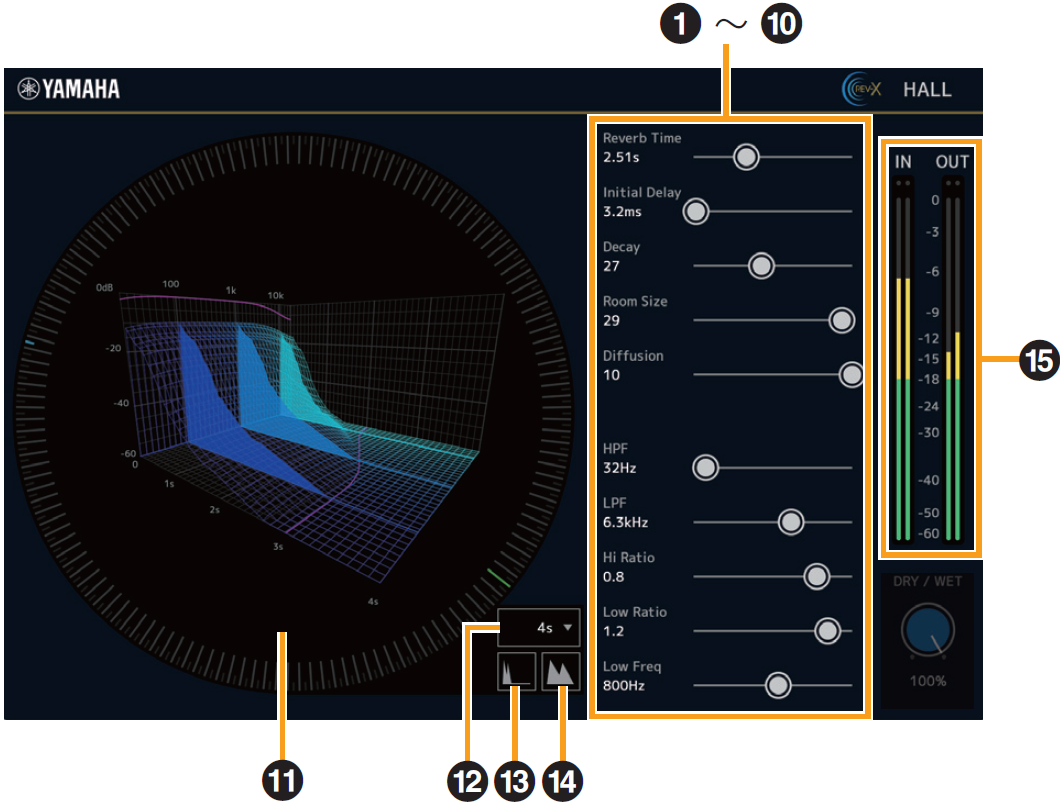
- ➊ Reverb Time
-
Adjusts the reverb time. This parameter links to Room Size.
The adjustable range varies depending on the REVX type.
| REV-X type | Range |
|---|---|
|
Hall |
0.289 sec–29.0 sec |
|
Room |
0.260 sec–26.0 sec |
|
Plate |
0.333 sec–33.3 sec |
- ➋ Initial Delay
-
Adjusts the time that elapses between the direct, original sound and the initial reflections that follow it.
Range : 0.1 msec–200.0 msec - ➌ Decay
-
Adjusts the characteristic of the envelope from the moment the reverberation starts to the moment it attenuates and stops.
Range : 0–63 - ➍ Room Size
-
Adjusts the size of the simulated room. This parameter links to Reverb Time.
Range : 0–31 - ➎ Diffusion
-
Adjusts the spread of the reverberation.
Range : 0–10 - ➏ HPF
-
Adjusts the cutoff frequency of the high pass filter.
Range : 20 Hz–8.0 kHz - ➐ LPF
-
Adjusts the cutoff frequency of the low pass filter.
Range : 1.0 kHz–20.0 kHz - ➑ Hi Ratio
-
Adjusts the duration of reverberation in the high frequency range by using a ratio relative to the Reverb Time. When you set this parameter to 1, the actual specified Reverb Time is fully applied to the sound. The lower the value, the shorter the duration of reverberation in the high frequency range.
Range : 0.1–1.0 - ➒ Low Ratio
-
Adjusts the duration of reverberation in the low frequency range by using a ratio relative to the Reverb Time. When you set this parameter to 1, the actual specified Reverb Time is fully applied to the sound. The lower the value, the shorter the duration of reverberation in the low frequency range.
Range : 0.1–1.4 - ➓ Low Freq
-
Adjusts the frequency of the Low Ratio.
Range : 22.0 Hz–18.0 kHz - ⓫ Graph
-
Indicates the characteristics of reverberation. The vertical axis indicates the signal level, the horizontal axis indicates the time, and the Z-axis indicates the frequency. You can adjust the characteristics of reverberation by dragging the handles in the graph.
- ⓬ Time Axis Setting
-
Selects the display range of the time (horizontal axis) on the graph.
Display range : 500 msec–50 sec - ⓭ Zoom Out
-
Zooms out the display range of the time (horizontal axis) on the graph.
- ⓮ Zoom In
-
Zooms out the display range of the time (horizontal axis) on the graph.
- ⓯ Level Meters
-
Displays the input/output level from REV-X.
Software operation
• You can reset certain parameters to their default values by holding the [Ctrl]/[Command] key while you click on the appropriate knobs, sliders, and faders.
• You can adjust the parameters more finely by holding the [Shift] key while you drag on the appropriate knobs, sliders, and faders.
DELAY
You can select Delay as an effect type in the REV-X area.
These can be used with all sampling frequencies.
How to Open the Screen
・
From dspMixFx UR-C
After Delay is selected in the REV-X area, click “REV-X Edit.”
・
From Dedicated Windows for Cubase Series
Select Delay for “REV-X Type” in the effect setting area.Click “REV-X Edit” to start dspMixFx UR-C, and the dspMixFx UR-C Delay screen will open.
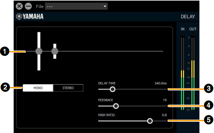
- ➊ Graph
-
Visually displays Delay settings and their effects. Cannot be operated.
- ➋ MONO/STEREO switching
-
Switches the delay type.
MONO : The left and right delay times will be the same.
STEREO : This effect applies a delay alternately to the left and right. This cannot be selected when the sampling frequency is 176.4 kHz or 192 kHz. - ➌ DELAY TIME
-
Sets the delay time.
Range : 0.1 ms–1300.0 ms - ➍ FEEDBACK
-
Sets the amount of delay feedback.
Range : 0–63 - ➎ HIGH RATIO
-
Sets the amount of high frequency component included in the feedback.
Range : 0.1–1.0
GATE
If a signal that is lower than the THRESHOLD is input, this reduces the output by a fixed value (RANGE). Use this when you do not want environmental noise to be added to the stream. This can be used as a streaming effect in the path from the input channel to the streaming mix, but does not affect the recording signal sent from the channel to the DAW.
This unit has two Gates available. These can be used with all sampling frequencies.
How to Open the Screen
This is displayed when Streaming mix is selected in the dspMixFx UR-C’s MIX area, select Gate in the channel area’s “Streaming Effect Type”, and then click “Edit effect.”
Operations cannot be performed from the Cubase series dedicated screen.
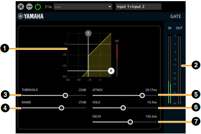
- ➊ Graph
-
This visually displays the gate’s THRESHOLD and
RANGE settings. You can also operate the (T) handle for THRESHOLD and the (R) handle for RANGE. - ➋ Gain Reduction Meter
-
This displays the amount of gain reduction for the gate.
- ➌ THRESHOLD
-
Sets the threshold level at which the gate effect is applied.
Range : −72 dB–0 dB - ➍ RANGE
-
Sets the amount of attenuation when the gate effect is applied.
Range : −∞, −72 dB–0 dB - ➎ ATTACK
-
Sets how quickly the gate opens after the input signal level exceeds the THRESHOLD.
Range : 0.092 ms–80.00 ms - ➏ HOLD
-
Sets the time to wait before the gate begins to close after the input signal level drops below THRESHOLD.
Range : 0.02 ms–1960.0 ms - ➐ DECAY
-
Sets how quickly the gate closes after the input signal has passed the HOLD wait time.
Range : 9.3 ms–999.0 ms
COMPRESSOR
Volume changes can be adjusted by compressing the portion of the signal level that exceeds the THRESHOLD. This can be used as a streaming effect in the path from the input channel to the streaming mix, but does not affect the recording signal sent from the channel to the DAW.
This unit has two Compressors available. These can be used with all sampling frequencies.
How to Open the Screen
This is displayed when Streaming mix is selected in the dspMixFx UR-C’s MIX area, select Comp in the channel area’s “Streaming Effect Type”, and then click “Edit effect.”
Operations cannot be performed from the Cubase series dedicated screen.
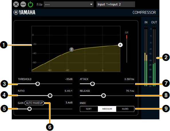
- ➊ Graph
-
Visually displays the compressor’s THRESHOLD, RATIO and GAIN settings. You can also operate the (T) handle for THRESHOLD and the (R) handle for RATIO.
- ➋ Gain Reduction Meter
-
Displays the amount of gain reduction for the compressor.
- ➌ THRESHOLD
-
Sets the threshold level at which the compressor effect is applied.
Range : −54 dB–0 dB - ➍ RATIO
-
Sets the amount of compression for the compressor.
Range : 1.00:1–INF:1 - ➎ GAIN
-
Sets the output level of the compressor. When Auto Makeup is on, this will be set automatically and cannot be operated.
Range : 0.0 dB–18.0 dB - ➏ Auto Makeup
-
When set to ON, the GAIN is automatically set using the THRESHOLD and RATIO settings.
- ➐ ATTACK
-
Automatically sets the speed at which the compressor effect reaches its maximum once the input signal level exceeds the THRESHOLD.
Range : 0.092 ms–80.00 ms - ➑ RELEASE
-
This is the time it takes for the compressor effect to disappear after the input signal falls below the THRESHOLD.
Range : 9.3ms–999.0ms - ➒ KNEE
-
Sets the smoothness (sharpness) of volume changes near the THRESHOLD setting level.
| Options | Description |
|---|---|
|
SOFT |
The volume changes naturally. |
|
MEDIUM |
Between Hard and Soft. |
|
HARD |
The volume changes are noticeable. |
DUCKER
Automatically attenuates the sound of the DAW/Music/Voice channel for the input audio from the Input1/2 and Voice channels. You can create an environment in which the background music is played at a low volume while you are talking on the microphone or while you are talking from the chat application, and then the background music is played at the original volume in all other cases.
It can be used as a streaming effect for routes from the DAW/Music/Voice channels to the streaming mix.
This unit has 2 duckers available. These can be used with all sampling frequencies.
How to Open the Screen
This is displayed when Streaming mix is selected in the dspMixFx UR-C’s MIX area, select Ducker in the DAW/Music/Voice area’s “Streaming Effect Type”, and then click “Edit effect.”
Operations cannot be performed from the Cubase series dedicated screen.
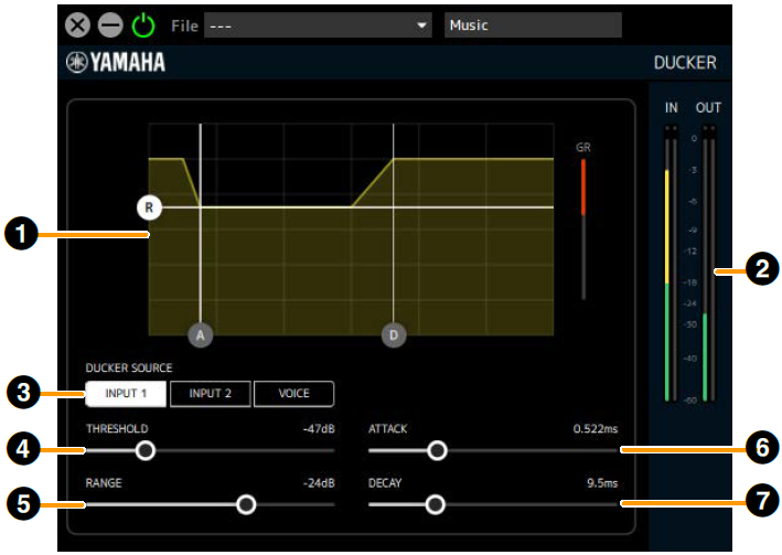
- ➊ Graph
-
Visually displays the change in output level over time from the beginning of the Ducker effect to the end of effect. You can also operate the (A) handle for ATTACK, the (D) handle for DECAY, and the (R) handle for RANGE.
- ➋ Gain Reduction Meter
-
Displays the amount of gain reduction for the ducker.
- ➌ DUCKER SOURCE
-
Sets the signal used to determine the strength of the ducker.
You can configure the settings for multiple signals.
INPUT1 : Signal from Input1 channel to Streaming mix (post-fader)
INPUT2 : Signal from Input2 channel to Streaming mix (post-fader)
VOICE : Signal from Voice channel to Streaming mix (postfader) - ➍ THRESHOLD
-
Sets the threshold level at which the ducker effect is applied.
Range : −60 dB–0 dB - ➎ RANGE
-
Sets the amount of attenuation when the ducker effect is applied.
Range : −70 dB–0 dB
- ➏ ATTACK
-
Sets how quickly the volume lowers after the input signal level exceeds the THRESHOLD.
Range : 0.092 ms–80.00 ms - ➐ DECAY
-
Sets how quickly the volume returns after the input signal level falls below the THRESHOLD.
Range : 1.3 ms–5.0 s
MULTI-BAND COMPRESSOR
By using a multi-band compressor algorithm and setting the compressor for each LOW/MID/HIGH band, you can suppress changes in the stream volume and increase the sound pressure.
Can be used at the final output stage of a streaming mix.
This can be used when the sampling frequency is 44.1 kHz, 48 kHz, 88.2 kHz or 96 kHz.
How to Open the Screen
This is displayed when Streaming mix is selected in the dspMixFx UR-C’s MIX area, then select M.B. Comp in the channel area’s “Streaming Effect Type”, and then click “Edit effect.”
Operations cannot be performed from the Cubase series dedicated screen.
[When Graph (Band Division Overview) is clicked]
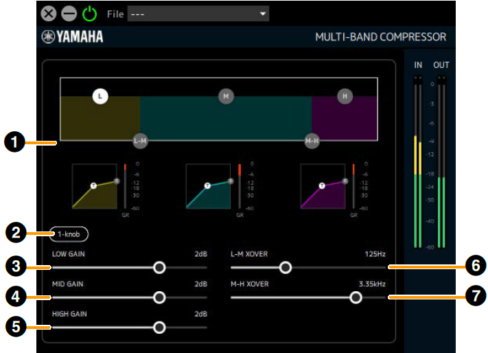
- ➊ Graph (Band Division Overview)
-
Sets the band division for each of the LOW/MID/HIGH bands and displays the level of each band in simplified form.
Use the (L) handle to set LOW GAIN, the (M) handle to set MID GAIN, and the (H) handle to set HIGH GAIN.
The L-M XOVER settings can be operated using the (L-M) handle and the M-H XOVER settings can be operated using the (M-H) handle.
Click this area to display the parameters for ➌-➐ below. - ➋ 1-knob
-
This function controls the effect of Multi-Band Compressor with a single slider. When 1-knob is turned on, a slider will appear, and you can operate the slider to control THRESHOLD, RATIO, and GAIN of each band.
ATTACK, RELEASE and XOVER frequencies are fixed values. 1-knob will be displayed when you click on any graph.
|
[When 1-knob is off] |

|
|
[When 1-knob is on] |

|
- ➌ LOW GAIN
-
Sets the volume of the LOW band.
Range : −∞, −60 dB–+18 dB - ➍ MID GAIN
-
Sets the volume of the MID band.
Range : −∞, −60 dB–+18 dB - ➎ HIGH GAIN
-
Sets the volume of the HIGH band.
Range : −∞, −60 dB–+18 dB - ➏ L-M XOVER
-
Sets the crossover frequency between the LOW band and MID band.
Range : 21.2 Hz–4.00 kHz - ➐ M-H XOVER
-
Sets the crossover frequency between the MID band and HIGH band.
Range : 42.5 Hz–8.00 kHz
[When LOW band graph is clicked]
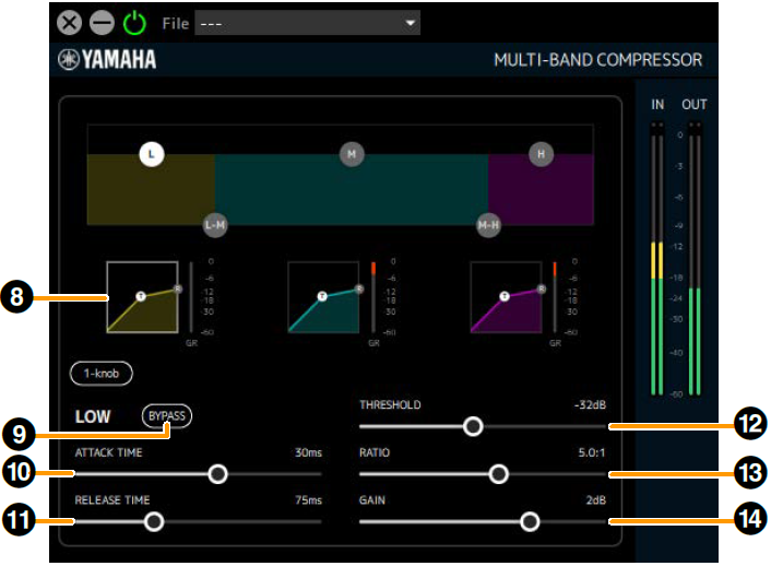
- ➑ LOW Band Graph
-
Visually displays the LOW band compressor’s THRESHOLD, RATIO and GAIN settings. You can also operate the (T) handle for THRESHOLD and the (R) handle for RATIO. Also displays a gain reduction meter to the right of the graph. Also displays a gain reduction meter to the right of each graph. Click this area to display the parameters for ➒–⓮ below.
- ➒ BYPASS (LOW)
-
Turns the LOW band compressor bypass on or off.
- ➓ ATTACK TIME (LOW)
-
Sets the LOW band compressor attack time.
Range : 1 ms–200 ms - ⓫ RELEASE TIME
-
Sets the compressor (Common to all bands) release time.
Range : 10 ms–3000 ms - ⓬ THRESHOLD (LOW)
-
Sets the LOW band compressor THRESHOLD.
Range : −54 dB–−6 dB - ⓭ RATIO (LOW)
-
Sets the LOW band compressor RATIO.
Range : 1.0:1–20.0:1 - ⓮ GAIN (LOW)
-
Same as ➌.
[When MID band graph is clicked]
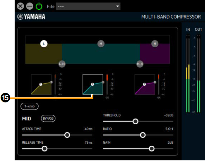
- ⓯ MID Band Graph
-
Visually displays the MID band compressor’s THRESHOLD, RATIO and GAIN settings. You can also operate the (T) handle for THRESHOLD and the (R) handle for RATIO. Also displays a gain reduction meter to the right of the graph. Also displays a gain reduction meter to the right of each graph. Clicking on this area displays the parameters of the MID band compressor. (The details for each parameter are the same as for the LOW band.)
[When HIGH band graph is clicked]
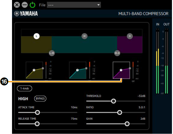
- ⓰ HIGH Band Graph
-
Visually displays the HIGH band compressor’s THRESHOLD, RATIO and GAIN settings. You can also operate the (T) handle for THRESHOLD and the (R) handle for RATIO. Also displays a gain reduction meter to the right of the graph. Clicking on this area displays the parameters of the HIGH band compressor. (The details for each parameter are the same as for the LOW band.)