DAW Software
DAW Software
Cubase AI allows you to record and edit audio through dspMixFx. For detailed instructions, refer to the “Cubase AI Operation Manual” on the Steinberg website.
If you are using DAW software other than the Cubase series, refer to the User Guide for your UR-C/URX-C series device for setup instructions.
Dedicated Windows for Cubase Series (DAW)
These are the windows for configuring the device settings from Cubase series software. The dedicated windows for Cubase series allow you to configure the parameters which are configured by dspMixFx UR-C. Two types of windows are available: Input Settings and Hardware Setup.
|
Input Settings Window |
Hardware Setup Window |
|
|
How to Open the Window
Input Settings Window
In the Cubase series menu, select [Project] → [Add Track] → [Audio] to create an audio track, and then click the [URxxC] tab displayed in the inspector on the left side of the screen. (xx will be replaced with the model name of your device.)
Hardware Setup Window
・
From the Cubase series menu
Select [Studio] → [Studio Setup], then select the [Steinberg UR-C] on the [Steinberg I/O] on the left side.
・
From Input Settings Window
Open the Input Settings Window and click [Hardware Setup] in the header area.
Input Settings Window
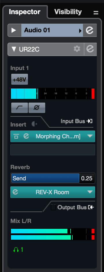
This window is for configuring the input settings of the device. The signal flow is from top to bottom. The settings on this window (except for the +48V indicator) are saved to the Cubase project file.
The Input Settings Window is displayed on the audio track routing as URxxC. (xx will be replaced with the model name of your device.)
Header Area
Displays the names of connected devices and opens/closes the Editor.
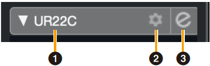
- ➊ model
-
Displays the model name (URxxC) in use. Switch between displayed or not displayed for the Input Settings Window by clicking it.
- ➋ Hardware setup
-
Opens the Hardware Setup Window.
- ➌ Editor Active
-
Opens dspMixFx UR-C.
Hardware Inputs Settings area
This area is used to set parameters related to the UR44C inputs.
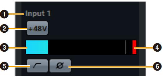
- ➍ Port name
-
Displays the name of the port which is being used for input to the track of the device.
- ➎ +48V
-
Indicates the on (lit) and off (unlit) status of the phantom power function of the device.
- ➏ Input meter
-
Displays input levels.
- ➐ Meter Clip
-
Displays the input meter clip when clipping occurs. Click this to stop this display.
- ➑ High Pass Filter
-
Turns on (lit) and off (unlit) the high pass filter (URX44C: Not available on [LINE INPUT 5/6]).
To select the cutoff frequency of the high pass filter, use the “Hardware Setup Window” in the section “dspMixFx UR-C.” - ➒ Phase
-
Switches phase inversion on (lit) and off (unlit). Shows L, R when stereo is selected.
Effect Settings area
This area is used to set parameters related to the UR44C input/output port effects.
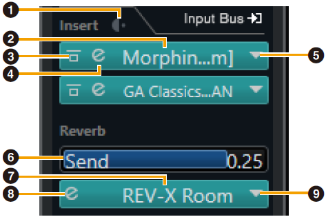
- ➊ Pre/Post
-
Used to select the insertion point for the effect.
- ➋ Effect Name
-
Displays the names of the applied effects.
- ➌ Effect Bypass
-
Enables/bypasses the effect.
- ➍ Effect Edit
-
Displays the Effect Edit window.
- ➎ Effect Type
-
Selects the effect type.
Settings : No Effect, Ch.Strip, Clean, Crunch, Lead, Drive, Pitch FixNOTE
The maximum number of effects that can be used simultaneously is limited.Refer to “Limitations on the use of effects” in the User Guide for your UR-C/URX-C series device. - ➏ REV-X Send
-
Adjusts the signal level which is sent to REV-X.
Range : −∞ dB–+6.00 dB - ➐ REV-X Name
-
Displays the selected REV-X type.
- ➑ REV-X Edit
-
Opens the “REV-X” setup window.
- ➒ REV-X Type
-
Selects the REV-X type.
Settings : Hall, Room, Plate, Delay
Outputs area
This area is used to set parameters related to hardware outputs.
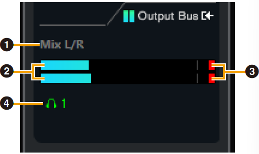
- ➊ Mix Bus name
-
Displays the Mix Bus name of the hardware output. The output bus of the track must be connected to this Mix bus.
- ➋ Output meter
-
Displays meters for the hardware Mix Bus connected to hardware outputs.
- ➌ Meter Clip
-
Displays the input meter clip when clipping occurs. Click this to stop this display.
- ➍ Headphones
-
UR22C/URX22C : Headphone 1 is on at all times.
UR44C/URX44C/UR816C : Patches headphones to the hardware Mix Bus connected to hardware outputs.
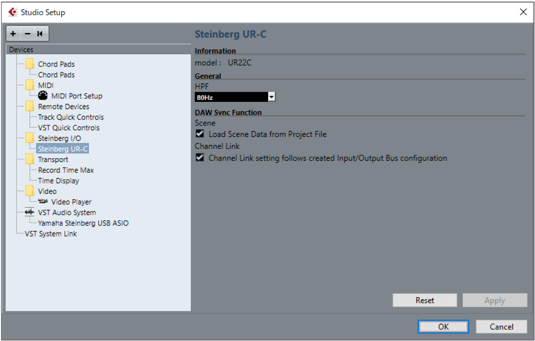
Hardware Setup Window
This window allows you to configure general hardware settings and Cubase-linked function settings.
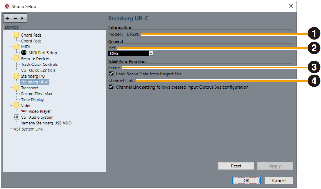
- ➊ model
-
Displays the name of the device.
- ➋ HPF
-
Selects the cutoff frequency of the high pass filter (URX44C: Not available on [LINE INPUT 5/6]).
Settings : 120 Hz, 100 Hz, 80 Hz, 60 Hz, 40 Hz - ➌ Scene
-
When a Cubase project file that includes scenes for the device is imported, the scene information is automatically applied to the device.
NOTICE
Data saved to the device will be overwritten. - ➍ Channel Link
-
Automatically configures stereo links based on the bus configuration in use.
UR44C/URX44C only
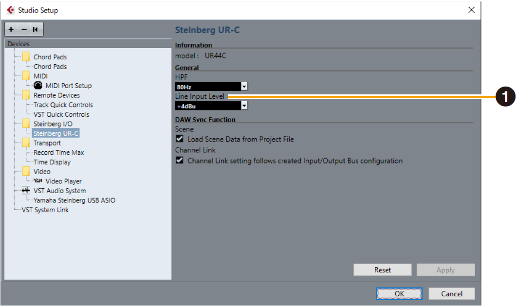
- ➊ LINE Input Level
-
Selects the input signal level of [LINE INPUT 5/6].
Options : +4 dBu, −10 dBV
UR816C only
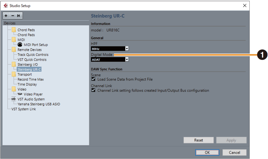
- ➊ Digital Mode
-
Selects the input and output signal format of the [OPTICAL IN] and [OPTICAL OUT] jack.
Options Description ADAT
Input and output signals of up to 8 channels.
S/PDIF
Input and output 2 channel signals.
With the ADAT format, the number of channels for input and output signals varies depending on the sampling frequency.
44.1 kHz/48 kHz : 8 channels
88.2 kHz/96 kHz : 4 channels
176.4 kHz/192 kHz : 2 channelsWith the S/PDIF format, a 2-channel signal is input and output at all sampling frequencies.