About the OVERVIEW window
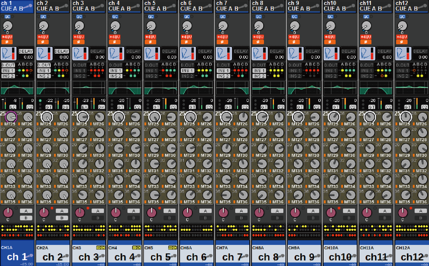
This window displays the main parameters for the 12 channels selected for the layer all at once.
Channel name area
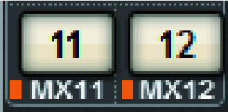
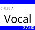
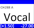
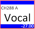
The upper part of the channel name area displays the channel number and the setting status of the patch and VSC. The middle part of the channel name area displays the channel name and channel icon. The lower part of the channel name are displays the overlay and fader status.
Selected channel | |
Channel is on |
|
Unselected channel | |
Channel is on |
|
Channel with overlay turned on |
|
Channel with Isolate turned on |
|
Temporarily linked channel |
|
Unassigned channel |
|
HA GAIN field
Sets the analog gain/digital gain of the HA (head amp). This also displays the operational status of the HA. The displayed contents of this field changes depending on the status of patches and the system configuration.
For analog gain
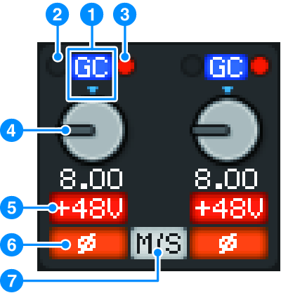
a | GC indicator If the Gain Compensation function is turned on, this indicator will appear, showing the fixed gain value of the signal output to the TWINLANe network or Dante network. |
b | PRE GC OVER indicator Illuminates to indicate that a signal is clipped before gain compensation. |
c | POST GC OVER indicator Illuminates to indicate that a signal is clipped after gain compensation. |
d | ANALOG GAIN knob Displays the HA analog gain setting value. Use the screen encoder to adjust the gain. If gain compensation is turned on, an indicator shows the analog gain position at the time that gain compensation was turned on. |

e | +48V indicator Displays the phantom power (+48V) on or off status for the head amp. This indicator is not displayed unless the head amp is patched to the channel. |
f | Indicator Displays the phase setting status for the head amp input. |
g | M/S indicator This indicator is displayed when the M/S Decode function is enabled. |
For digital gain
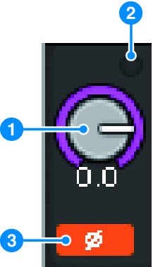
a | DIGITAL GAIN knob Displays the digital gain setting value. Use the screen encoder to adjust the digital gain. If the Gain Compensation function is turned on, this knob will adjust the level of the signal input to the input channel. |
b | OVER indicator Illuminates when a signal at the input port or from the rack output is clipped. This indicator is displayed only if an input channel is selected. |
c | Indicator Displays the phase setting status for each channel. NOTE
|
SILK field
Displays the SILK setting status. A bar graph on the right displays the TEXTURE of the SILK processing.

DELAY field
This field displays the delay status of the corresponding input channel or output channels. Press this field to open the DELAY popup (12CH) popup window.
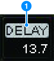
This field displays the delay status of the corresponding input channel or output channels. Press this field to open the DELAY popup (12CH) popup window.
a | DELAY ON/OFF indicator Indicates the on/off status of the delay. |
INSERT/DIRECT OUT field
This field allows you to make insert and Direct Out settings. Press this field to open the INSERT/D.OUT 1CH popup window.
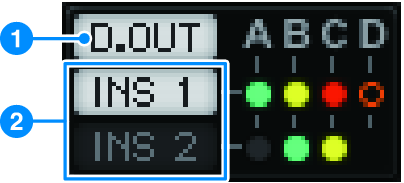
a | DIRECT OUT ON/OFF indicator (input channels only) Indicates the Direct Out on/off status. |
b | INSERT ON/OFF indicator Displays the Insert on/off status. The following indicators display the insert mount status: |
| A plug-in, GEQ/PEQ, or outboard unit is inserted at the insert point. |
| Bypassed |
| Level indicator Gray: -∞ Green: <–18 dB Yellow: –18 dB≤, ≤0 dB Red: 0 dB< |
EQ field

This field indicates the approximate EQ response characteristics. Press this field to open the HPF/EQ (1CH) popup window, where you can specify the HPF, LPF and EQ settings. This field will be grayed out on channels for which the EQ is disabled.
DYNAMICS 1/2 field
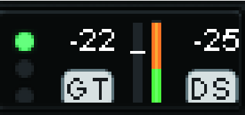
This field displays the threshold value, meter, and abbreviated dynamics processor type for Dynamics 1/2. Press this field to open the DYNAMICS 1/2 (1CH) popup window. If GATE is selected as the dynamics type, an indicator is displayed to indicate the gate status. If the dynamics processor is any type other than GATE, the abbreviated type name will be displayed in this field, and the threshold setting will be indicated as a horizontal line on the meter. For information on the abbreviated name and GATE indicators that are displayed, see (DYNAMICS1/2 popup window). In addition, the on/off status of the dynamics is displayed in the type.
SEND field
This field displays the send level, output bus name, and the send on/off status for 12 buses.
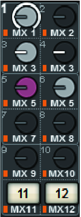
To select the 12 destination buses, use the MIX/MATRIX SENDS [1-12]/[13-24]/[25-36]/[37-48]/[49-60]/[61-72] keys on the panel. Use the screen encoders or the [TOUCH AND TURN] knob to adjust the send level for each bus. Press the knob of the bus you want to control to assign the knob to one of the screen encoders. If it is assigned to the [TOUCH AND TURN] knob, press the knob again to open the SENDS TO popup window. If the channels that are rolled out to a bay are MATRIX channels, press the knob to open the SENDS FROM popup window. This display for this field varies depending on the type of destination bus.
If the destination bus is VARI (mono):
The knob color and pointer color indicate the send on/off and pre/post status. If the send is off, the knob color will turn gray. With the post setting, the knob pointer color will turn black.

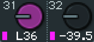
If the destination bus is VARI (stereo):
If a pair of buses (odd-numbered and even-numbered) are in stereo, the left-hand knob will function as the PAN knob, and the right-hand knob will function as the SEND knob.
If the destination bus is set to FIXED:
The SEND ON/OFF button for each bus is shown instead of the knob.
TO STEREO field
This field displays the on/off status and pan/balance setting of the signal sent to the STEREO bus. Press this knob and you will be able to use the screen encoder and the [TOUCH AND TURN] knob to adjust the value. If you press the knob once again, the TO STEREO popup window will appear. This field varies depending on the type of the selected channel.
When an input channel or MIX channel is selected:
a | TO STEREO PAN knob Sets the pan/balance of a signal routed to the STEREO bus. Press the knob to open the TO STEREO popup window. |
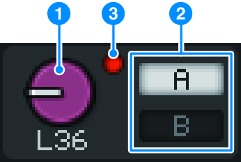
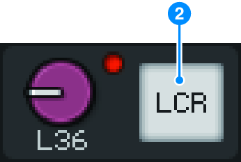
b | TO ST A/TO ST B indicators Displays the status of a signal sent to the STEREO A bus/STEREO B bus. If an input or MIX channel is set to LCR mode, the LCR indicator will be displayed. |
c | ∑ clipping indicator Illuminates to indicate that a signal is clipped at some point in the channel. |

When MATRIX or STEREO channels are selected:
If STEREO channels are selected, the stereo balance will be displayed. Also, If MATRIX channels are paired, the balance will be displayed. The Σ clip indicator will be displayed if the signal is clipped at some point within the channel.
DCA field
A DCA (1–24) to which the channel is assigned is displayed on the first and/or second row in this field. Press this field to open the DCA/MUTE ASSIGN (1CH) popup window.
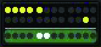
- Each indicator will flash when the muted channel MUTE GROUP CONTROL is ON or DCA MAIN is OFF.
Mute group field
The mute group (1-12) to which the channel is assigned is displayed on the third row in this field. If that channel has been temporarily removed (SAFE) from the mute group, a highlight is applied. Press this field to open the DCA/MUTE ASSIGN (1CH) popup window.
- Press the [SHIFT] key to display the send block switching button in the DCA/Mute group field.




 RIVAGE PM Series