


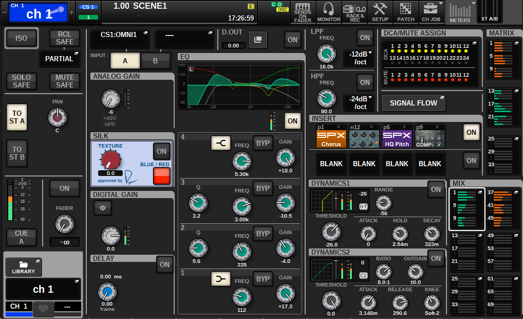
About the SELECTED CHANNEL VIEW window
This window shows all mix parameters of the currently-selected channel.
ISOLATE
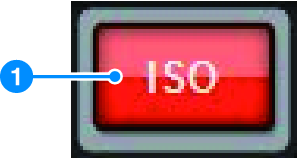
a | ON button Turns the Isolate function on and off. |
RECALL SAFE
This field allows you to specify the Recall Safe settings.
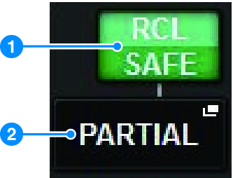
a | ON button Switches the Recall Safe status on or off. |
b | Popup button Press this button to open the RECALL SAFE popup window. This button will indicate “PARTIAL” if recall safe applies only to some of the parameters, not to all channel settings. It will indicate “All” if recall safe applies to all parameters. If no parameters are specified, it will indicate “OFF.” |
SOLO SAFE
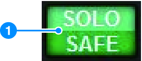
a | ON button Turns the Solo Safe function on and off. |
MUTE SAFE
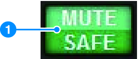
a | ON button Turns the Mute Safe function on and off. |
TO STEREO field
You can control the stereo balance of the signals sent from the selected channel to the STEREO bus, or the signals output from the MIX/MATRIX/STEREO buses. The indication varies depending on the selected channel, as follows.
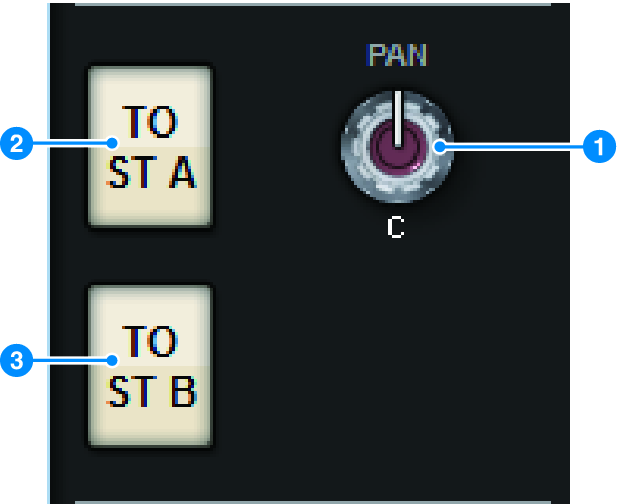
If the selected channel is an input channel or MIX channel:
Use the right-side PAN knob a to adjust the panning of the signal. Use the TO ST A button b to switch the signal to be sent to the STEREO A bus on or off. Use the TO ST B button c to switch the signal to be sent to the STEREO B bus on or off.
- If channels are paired for stereo, the PAN knob will be replaced with the BALANCE knob.
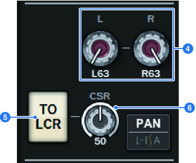
In the TO STEREO popup window, if the PAN/BALANCE select button is set to PAN, the L and R PAN knobsd are displayed, allowing you to specify the panning of the signal. If you use the ST/LCR mode select button to select LCR, the LCR button e and CSR knob f are displayed. The LCR button turns on/off the signal that is sent from the channel to the STEREO bus, and the CSR knob specifies the level ratio between the signal that is sent to the STEREO A (L/R) bus and to the STEREO B (C) bus.
Fader strip field
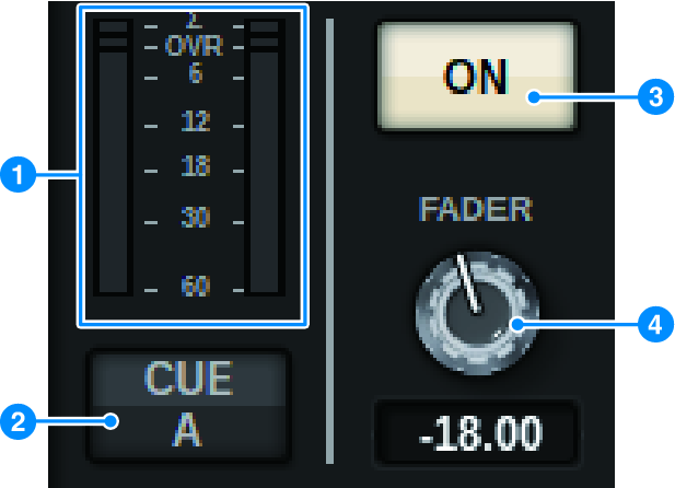
a | LEVEL meter Displays the POST ON level of a channel. |
b | CUE ON button Switches Cue Out on or off. The button also displays the selected cue bus(es). |
c | ON button Switches the channel on or off. |
d | FADER knob Adjusts the channel fader level. |
CH MODE field
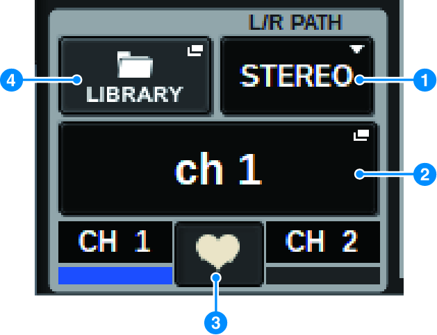
a | L/R PATH pull-down menu Displayed if the input channels are paired. You can select MONO, STEREO, L/L, or R/R as the audio combination input to the input channels. |
b | NAME popup buttons Press this button to display the NAME/ICON EDIT popup window. |
c | Pair setting popup button Press this button to display the “Setting or defeating pairing on the SELECTED CHANNEL VIEW screen”. |
d | LIBRARY popup button Press this button to open the library popup window, where you can store or recall input/output channel parameters (including the HA setting). |
PATCH field
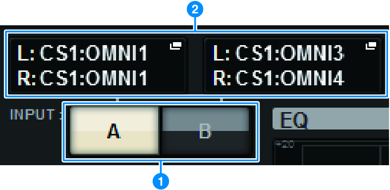
a | INPUT A/B switch buttons Switches between INPUT A and INPUT B. |
b | PATCH popup button Press this button to open the patch window. The button will display the patch setting. If the selected channel is a STEREO channel, or is a MIX/MATRIX channel that is assigned as a pair, an OUTPUT BALANCE knob is shown, enabling you to adjust the output balance. |
ANALOG GAIN field
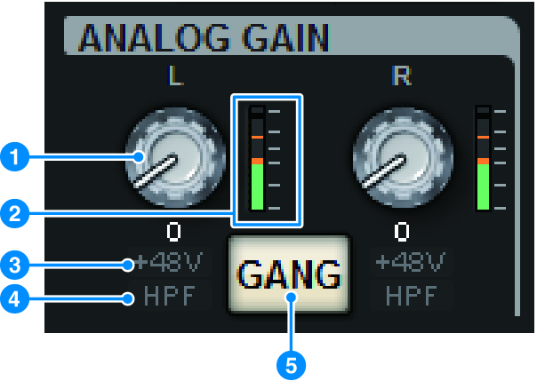
a | ANALOG GAIN knob Sets the HA analog gain. If the Gain Compensation function is turned on, a blue indicator appears, showing the analog gain position at the time the function was turned on. |
b | HA meter Displays the level immediately after the analog head amp. |
c | +48V indicator Displays the phantom power (+48V) on or off status for the head amp. |
d | HPF indicator Indicates the on/off status of the HPF immediately after the external head amp. |
e | GANG button This button is displayed if channels are paired. If this button is on, the differences in HA analog gain will be maintained, and the digital gain GANG button will also be turned on. |
SILK field
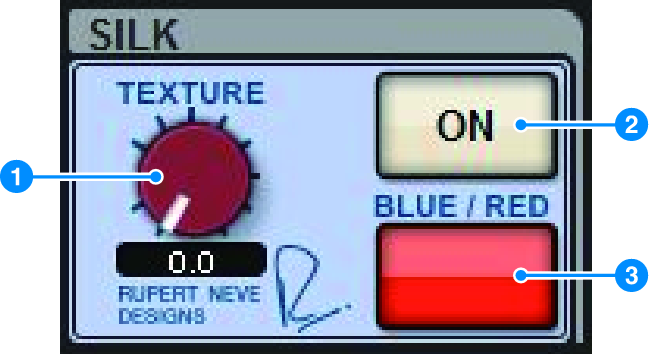
a | SILK [TEXTURE] knob Adjusts the Silk TEXTURE parameter. |
b | SILK [ON] key Switches Silk on or off. |
c | SILK [BLUE/RED] key Toggles between BLUE and RED Silk characters: “BLUE” for solidity and power, and “RED” for sparkling energy. |
DIGITAL GAIN field/PHASE field
|
|
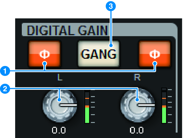
a | Ф (Phase) button Switches the phase of the head amp input signal between normal phase (gray) and reverse phase (orange). |
b | DIGITAL GAIN knob Displays the digital gain setting value. Use the screen encoder to adjust the digital gain. If the Gain Compensation function is turned on, this knob will adjust the level of the signal input to the selected channel. |
c | GANG button This button is displayed if channels are paired. If this button is on, the differences in digital gain will be maintained, and the digital gain GANG button will also be turned on. |
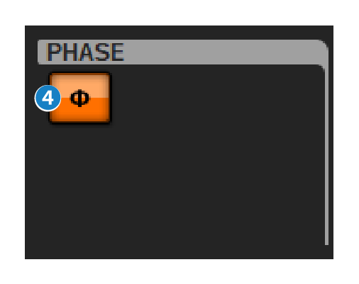
d | Polarity button Inverts the phase of the input and output signals. |
DELAY field
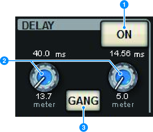
a | DELAY ON button Switches the delay function on or off for the selected channel. |
b | Delay time Displays the delay time. Use the corresponding screen encoder to adjust the delay time. In addition, you can press one of these values to display the DELAY TIME popup window, where you can set the delay time. |
c | GANG button This button is displayed if channels are paired. If this button is on, then differences in delay time will be maintained. |
DIRECT OUT field (input channels only)
This field allows you to turn Direct Out on/off for the selected input channel.
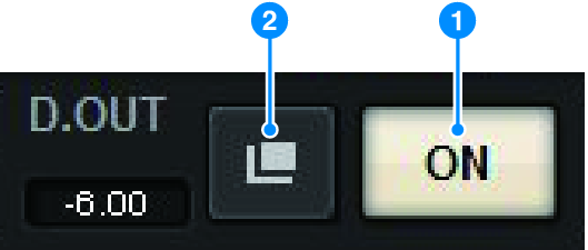
a | ON button Turns the Direct Out on or off. |
b | Direct Out patch popup button Press this button to open the “INSERT/D.OUT popup window (1CH)”. The Direct Out level value will appear to the left of the button. |
EQUALIZER field
IN | OUT |
| |
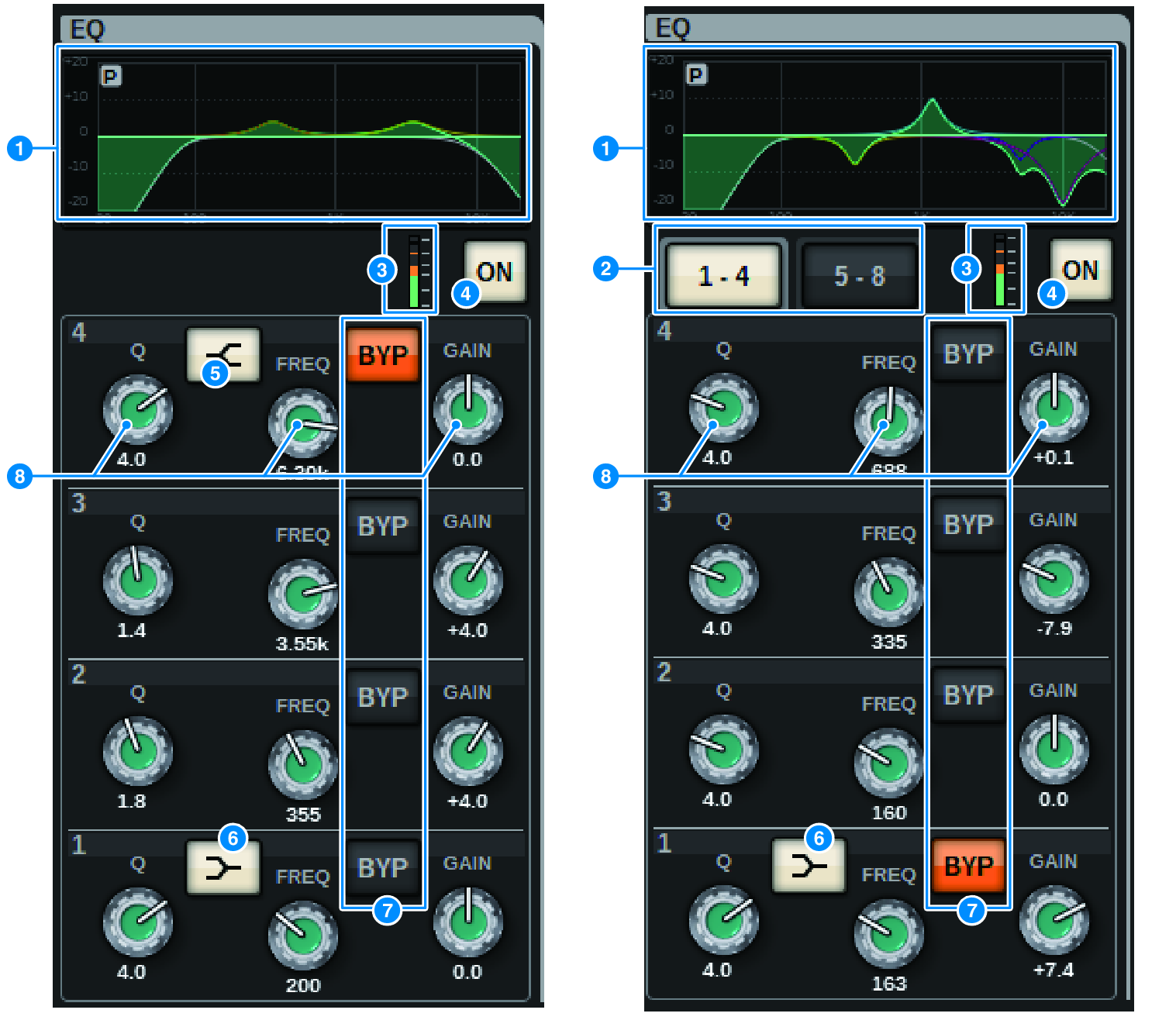
a | EQ graph This field indicates the approximate EQ response characteristics. Press this field to open the “EQ popup window (1ch)”, where you can set the HPF, LPF and EQ. |
b | Tabs (Output channels only) Use these tabs to select a band that you want to view on the screen. |
c | EQ IN/OUT level meters Indicate the peak level of signals before and after the EQ. For a stereo channel, these meters indicate the level of both the L and R channels. |
d | EQ ON/OFF button Switches the EQ on or off. |
e | HIGH SHELVING ON/OFF button Turn on this button to switch the HIGH band to a shelving type filter. |
f | LOW SHELVING ON/OFF button Turn on this button to switch the LOW band to a shelving type filter. |
g | BYP (BYPASS) button Temporarily bypasses the EQ for each band. |
h | EQ parameter setting knobs Indicate the Q, FREQUENCY, and GAIN parameters for each band. When this knob is pressed, the parameter name and value are displayed at the top of the channel name area and can be adjusted using the screen encoder. |
LPF field
This field allows you to set the LPF.
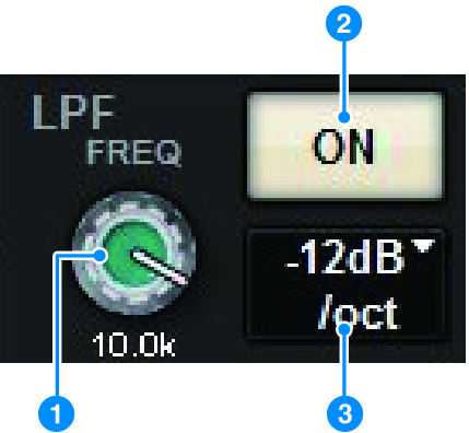
a | LPF knob Specifies the cutoff frequency of the low pass filter. |
b | ON button Switches the LPF on and off. |
c | LPF type select button Allows you to set the LPF attenuation per octave to −6 dB/oct or −12 dB/oct. |
HPF field
This field allows you to set the HPF.
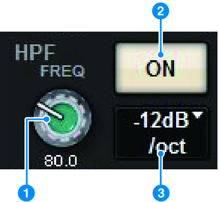
a | HPF knob Sets the HPF cutoff frequency. |
b | ON button Switches the HPF on and off. |
c | HPF type select button allows you to set the HPF attenuation per octave to −6 dB/oct, −12 dB/oct, −18 dB/oct, or −24 dB/oct. |
DCA/MUTE field
This field displays the DCA or mute group to which the channel is assigned.
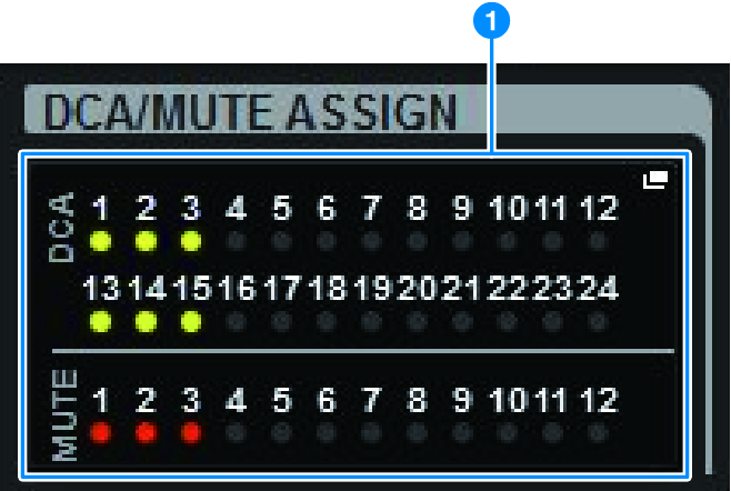
a | DCA/mute group popup button Indicates the DCA and mute group to which the channel is assigned. Press this button to open the DCA/MUTE ASSIGN (1CH) popup window. NOTE
|
INSERT field
This field allows you to specify insert settings.
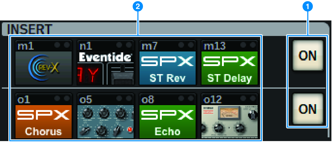
a | ON button Switches the insert on or off. |
b | Plug-in buttons If nothing is inserted, each button will display “BLANK.” If you press a BLANK button, a window will appear, where you can insert a plug-in. If a plug-in is already inserted, a window will appear, where you can set the plug-in parameters. Also, the level indicator will appear in the upper right. NOTE
|
DYNAMICS 1/DYNAMICS 2 field
This field allows you to view and set the Dynamics 1/2 parameters. Press the meter or the selected knob to open the DYNAMICS 1/2 popup window, where you can specify detailed parameter settings.
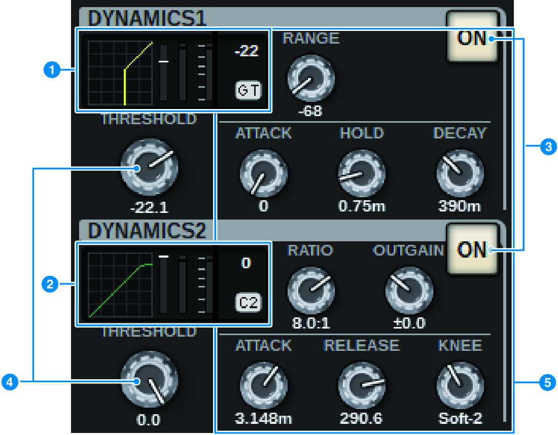
a | DYNAMICS 1 graph Indicates the abbreviated name of the dynamics processor type and the threshold value that are selected for Dynamics 1. The input/output characteristics graph, GR (gain reduction) meter, input/output level indicator, threshold values and dynamics type are displayed. |
b | DYNAMICS 2 graph (input channels only) Indicates the abbreviated name of the dynamics processor type and the threshold value that are selected for Dynamics 2. The input/output characteristics graph, GR (gain reduction) meter, input/output level indicator, threshold values and dynamics type are displayed. NOTE
|
Dynamics types | ||||||
|---|---|---|---|---|---|---|
GATE/DUCKING | THRESHOLD | RANGE | - | ATTACK | HOLD | DECAY |
COMP/EXPANDER | THRESHOLD | RATIO | OUTGAIN | ATTACK | RELEASE | KNEE |
DE-ESSER | THRESHOLD | FREQ | Q | - | - | TYPE |
FET LIMITER | INPUT | RATIO | OUTPUT | ATTACK | RELEASE | - |
DIODE BRIDGE COMP | THRESHOLD | RATIO | GAIN | - | RECOVERY | - |
c | ON button Switches the dynamics processor on or off. |
d | Threshold Sets the threshold. When this knob is pressed, the parameter name and value are displayed at the top of the channel name area. |
e | Parameter Displays the values of parameters that vary depending on the currently-selected dynamics type. When this knob is pressed, the parameter name and value are displayed at the top of the channel name area. |
MIX/MATRIX SENDS field
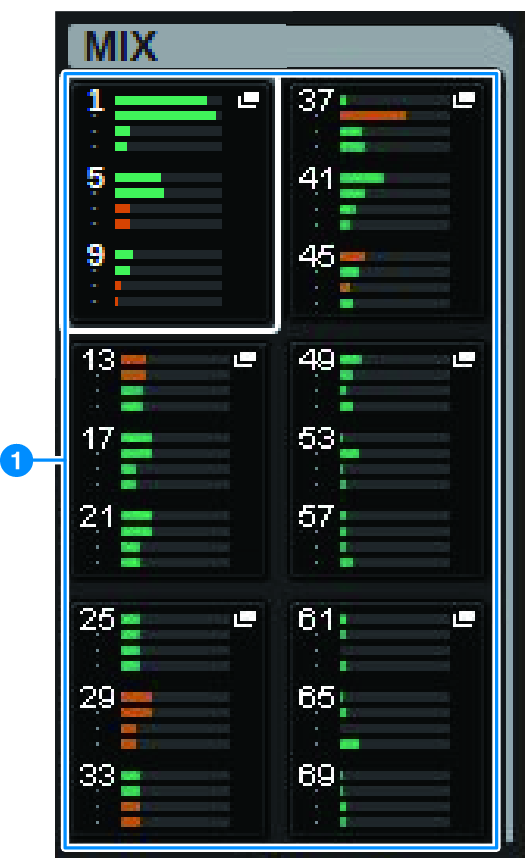
a | MIX popup buttons (input/MATRIX channels only) Displays the level sent from the channel selected by the input channel to the MIX bus. Displays the level sent from the MIX bus on the MATRIX channel to the selected channel. Press to roll out the send parameters to the screen encoder. Press again to switch between the SEND FROM and SEND TO windows. NOTE
|
On with PRE | On with POST |
| |
Off with PRE | Off with POST |
| |
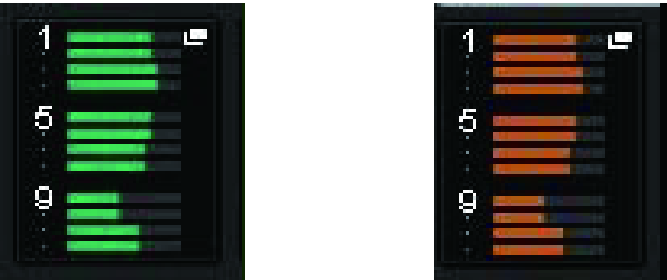
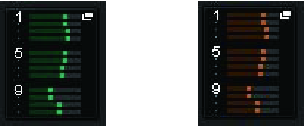
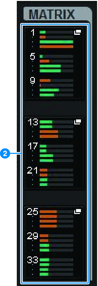
b | MATRIX popup buttons (input/MIX/STEREO channels only) Each button displays the level of the signal sent from the selected channel to the MATRIX bus. Press to roll out the send parameters to the screen encoder. Press again to switch between the SEND FROM and SEND TO windows. |
 RIVAGE PM Series