About GPI
The GPI connector located on the rear panel can be used as a GPI (General Purpose Interface) input/output connector. This connector provides eight GPI IN ports and eight GPI OUT ports. For example you can use an external switch to control internal parameters of the RIVAGE PM series or to switch scenes. Conversely, operations or scene changes performed on the RIVAGE PM series can send control signals to an external device. For details on how to send control signals to an external device when you switch scenes, refer to “Outputting a control signal to an external device in tandem with “Outputting a control signal to an external device in tandem with scene recall (GPI OUT)”.
The following diagram is an example of an external circuit that can operate GPI via the GPI connector. (For details on the specifications of the GPI connector pins, refer to the data list.) [OUT]-1–7 ports are open-drain outputs, and are switched to open or ground. Applicable voltage is up to +12V for the [OUT]-1–7 ports, and acceptable current is up to 75 mA per port. [OUT]-8 port supports up to +30V voltage input.
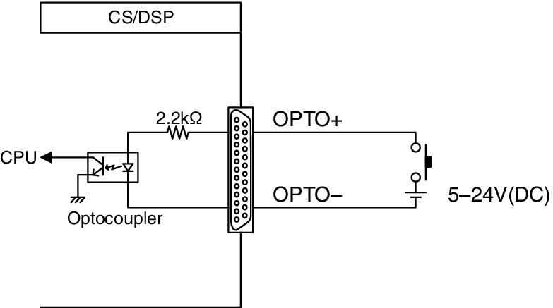
- Only [IN]-8 port features photo coupler input of up to +24V.
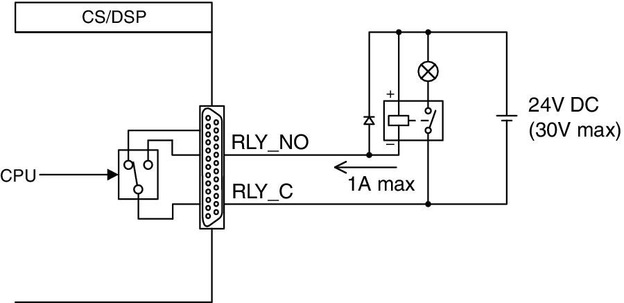
- Only [OUT]-8 port features relay output of 24V (DC) (rated) and 1A.
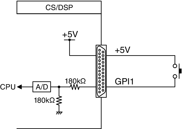
a | Using a switch connected to GPI IN1
|
b | Using a switch connected to GPI IN8
|
c | Lighting external LED indicators via GPI OUT1
|
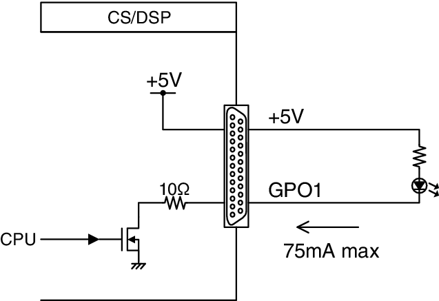

- Be careful not to exceed a current of 75 mA at the OUT ports.
d | Lighting a lamp (100V AC) by switching the relay on an external device via GPI OUT1
|
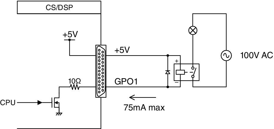
- Be careful not to exceed a current of 75 mA at the OUT ports.
e | Lighting a lamp (24V DC) by switching the relay on an external device via GPI OUT8
|