Wireless microphone system RM-W series
1. Overview
This is a wireless microphone system that can be used flexibly to suit the room and meeting style.
The RM-W series consists of the RM-WDR, RM-WOM, RM-WGS, and RM-WGL (wireless microphones), RM-WAP-8 and RM-WAP-16 (access points), and RM-WCH-8 (charging station, hereafter referred to as the charger). For details on the device, refer to the "RM-W Reference Manual."
| To control the "RM-WAP," you must set an initial password on the device and log in to it. |
2. "Project" sheet
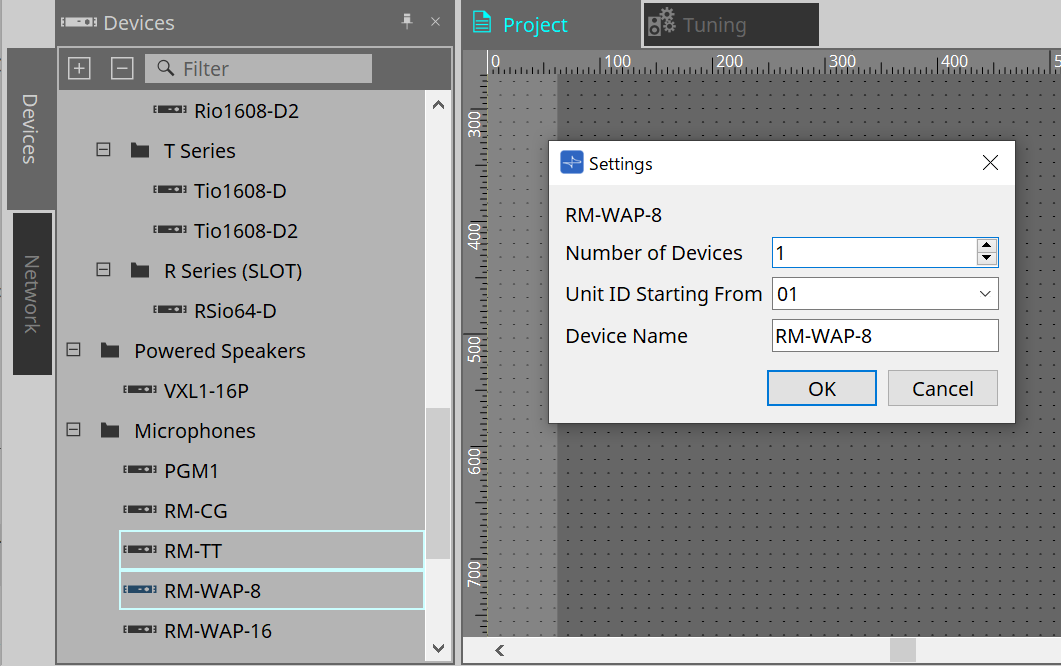
This is the sheet where you place devices. When placing a device, the Settings screen below will appear.
-
Number of Devices
Select the number of RM-WAP-8 or RM-WAP-16 devices to be placed on the sheet. -
Unit ID Starting From
You can select the starting number for the Unit IDs of devices. -
Device Name
You can view and edit the device name.
|
The devices to be placed on the Project sheet are RM-WA-8 and RM-WAP16. Microphones and chargers are operated by pairing them with the RM-WAP using the RM-WAP’s device sheet. |
3. [System] menu
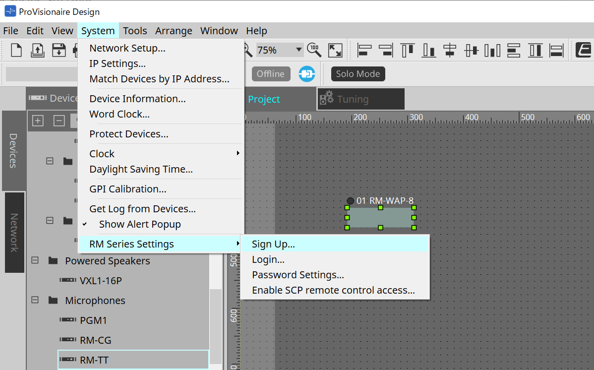
Configure the settings from RM Series Settings, which is displayed in the [System] menu on the menu bar.
-
RM Series Settings
-
Sign Up
Sets the initial password.
For details, refer to the dialog box. -
Login
Enter the password before controlling the device with ProVisionaire Design.
For details, refer to the dialog box. -
Password Settings
Changes the device password.
For details, refer to the dialog box. -
Enable SCP remote control access
Turn on this item to control devices with ProVisionaire Design or a remote controller.
For details, refer to the dialog box.
-
|
"Enable SCP remote control access" is automatically turned on when ProVisionaire Design and the devices are placed online. After configuring the device settings, reconfigure them if necessary. |
4. "Network" area
To control the "RM-WAP," you must set an initial password on the device and log in to it.
Right-click RM-WAP in Network and select Sign Up/Login.
Alternatively, use RM Series Settings, which is displayed in the [System] menu on the menu bar.
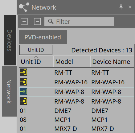
| You cannot configure the settings using ProVisionaire Design until you log in. |
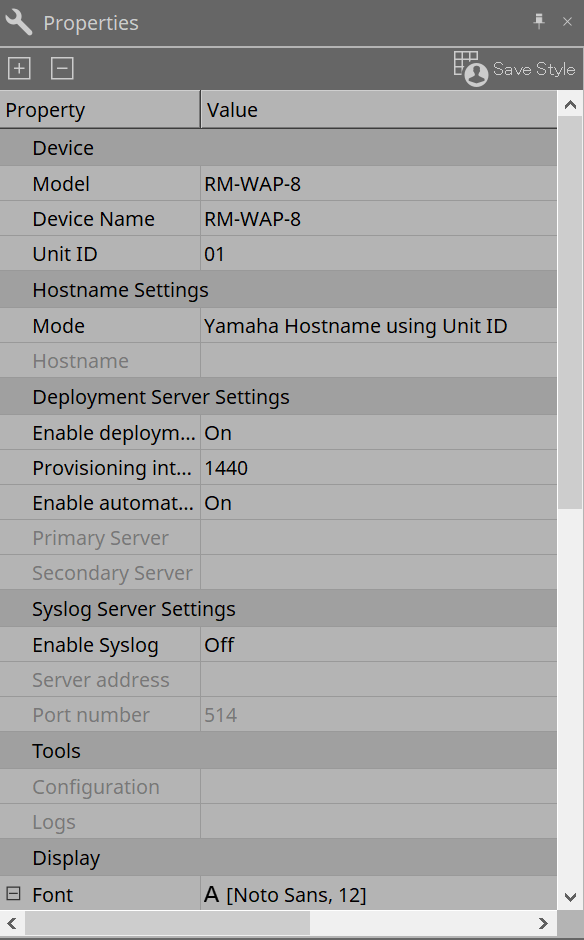
5. "Properties" area
For details on the device, refer to the "RM-W Reference Manual."
6. Screen structure of device sheet
When you open the device sheet of the RM-WAP, the device sheet and the "Bird’s Eye view" are displayed.
Double-click a component on the device sheet to open the component editor.
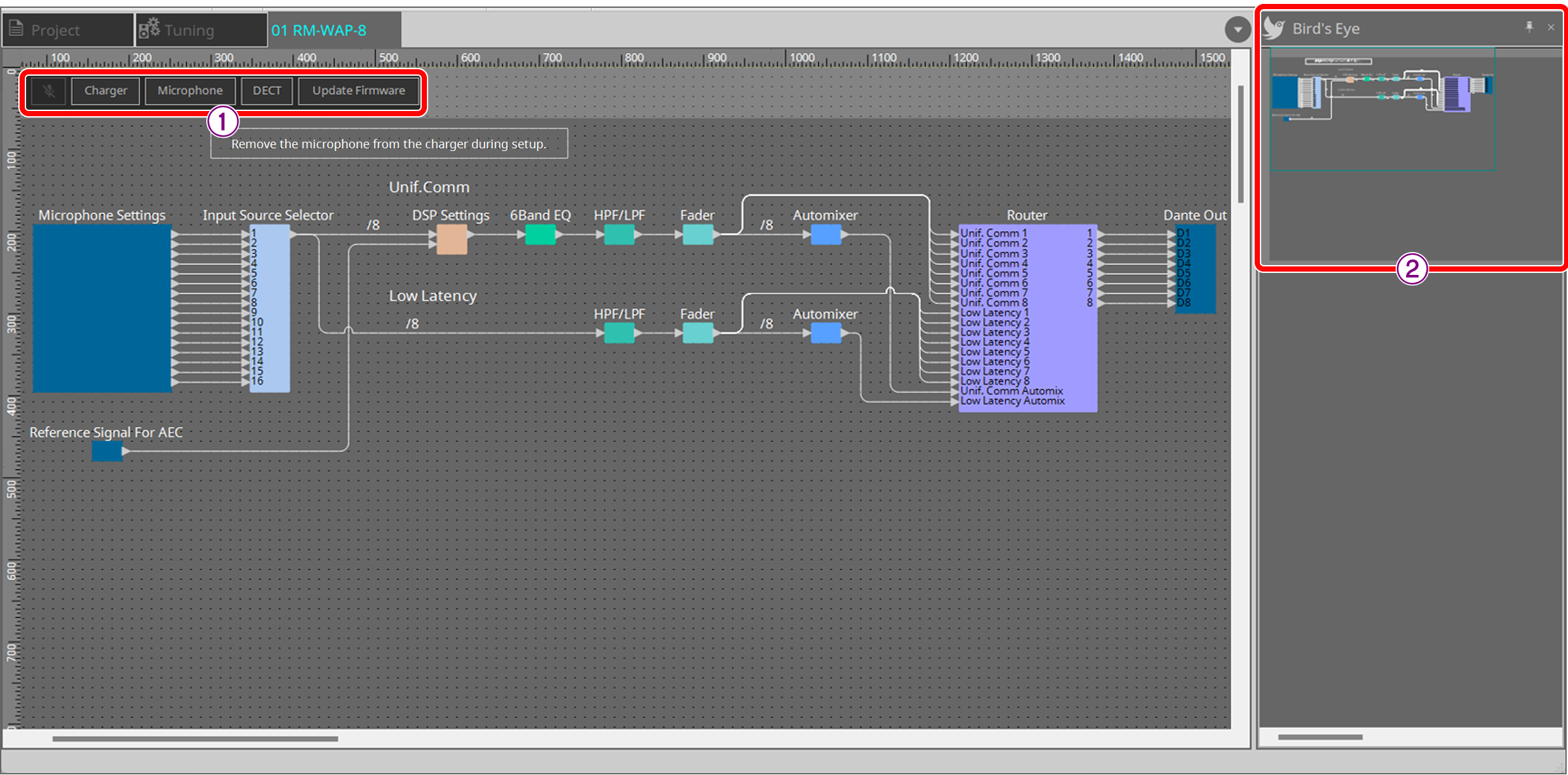
① Tool buttons
These are shortcut buttons for frequently-used commands in the RM-WAP.
② Bird’s Eye view
Shows the entire view of the sheet.
7. Tool buttons
These are shortcut buttons for frequently-used commands in the RM-WAP.
| Button | Command | Overview |
|---|---|---|
|
[All Mute] |
Mutes all microphones. |
|
[Charger] |
Pairs the RM-WAP with the RM-WCH (charger), and then pairs the RM-WAP with the microphone mounted on the RM-WCH. |
|
[Microphone] |
Pairs the RM-WAP with a microphone that is not mounted on the RM-WCH (charger). |
|
[DECT] |
Configures the DECT settings. |
|
[Update Firmware] |
Updates the RM-WCH and microphone paired with the RM-WAP. |


-
Charger button
Opens the "Charger" dialog box. -
Microphone button
Opens the "Microphone" dialog box. -
DECT button
Opens the "DECT" dialog box. -
Update Firmware button
Opens the "Update Firmware" dialog box.
8. Dialog boxes
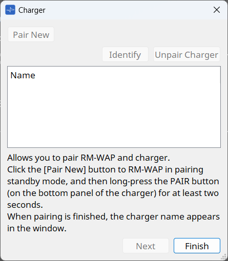
8.1. "Charger" dialog box
Pair the RM-WAP with the RM-WCH (charger), and pair the RM-WAP with the microphone mounted on the RM-WCH.
Click the button to open the dialog box.
8.2. Procedure
-
Place the microphone to be paired with the RM-WAP on the RM-WCH.
-
First, pair the RM-WAP with the RM-WCH.
-
Click the [Pair New] button.
The RM-WAP will enter standby mode.
The button will change to the [Cancel Paring] button.
To cancel the standby mode, click the [Cancel Pairing] button. -
In standby mode, press and hold the [PAIR] button on the bottom of the RM-WCH for at least 2 seconds.
The LED on the front [ACTIVATE] button will flash blue.
Once pairing is completed, the RM-WCH name will be displayed on the screen. Click the [Identify] button and the indicator of the selected RM-WCH will flash. -
When the RM-WCH name is displayed, click the [Next] button to move to the next page.
If the [Next] button is not enabled, click the [Cancel Pairing] button to enable the button.
To additionally pair another RM-WCH, return to step a and perform the pairing.
-
-
Next, pair the RM-WAP with the microphone mounted on the RM-WCH.
-
Press and hold the [ACTIVATE] button on the RM-WCH for 1 second.
Once pairing is completed, the microphone name will be displayed on the screen.
Click the [Identify] button and the indicator of the selected microphone will flash.
To unpair, click the [Unpair Charger] button.
-
-
Click the [Finish] button to close the dialog box.
8.3. "Microphone" dialog box
Pair the RM-WAP with a wireless microphone that is not mounted on the RM-WCH (charger).
Click the button to open the "Microphone" dialog box.
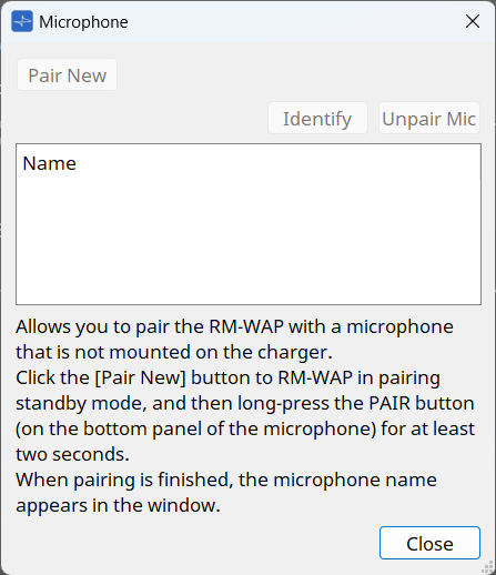
8.4. Procedure
-
Disconnect the microphone from the RM-WCH.
-
Click the [Pair New] button.
The RM-WAP will enter standby mode. -
In standby mode, press and hold the pairing button on the bottom of the microphone for at least 2 seconds.
Once pairing is completed, the microphone name will be displayed on the screen. Click the [Identify] button and the indicator of the selected microphone will flash.
Once the RM-WAP is paired with the microphone, the microphone name will be displayed above the "Microphone Settings" component.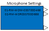
-
To unpair, click the [Unpair Mic] button.
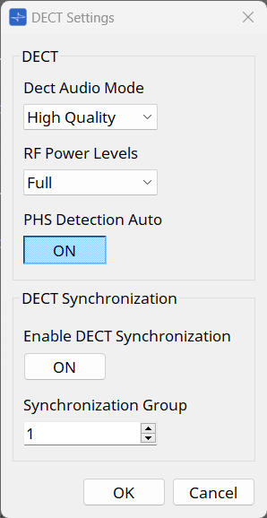
8.5. "DECT" dialog box
Click the button to open the "DECT Settings" dialog box.
-
DECT
-
Dect Audio Mode
Select audio mode.Selecting High Quality mode improves sound quality. However, because High Quality mode uses two DECT channels per microphone, the maximum number of microphones available is reduced compared to High Density mode. Select High Quality mode only if there are enough free channels for existing DECT communications. -
RF Power Levels
Select the radio field strength. The maximum communication distance is approximately 63.9 m at Full, approximately 29.6 m at High, approximately 13.7 m at Medium, and approximately 6.34 m at Low (straight line distance). However, this distance can vary greatly depending on the environment. -
PHS Detection Auto
If you disable PHS detection auto, the RM-WAP will not use carriers 3 and 4 that PHS systems may use. When this setting is enabled, the RM-WAP will use carriers 3 and 4 for the microphone system unless the PHS is detected.
-
-
DECT Synchronization
-
Enable DECT Synchronization
DECT Synchronization is used to synchronize RM-WAP systems that belong to the same Synchronization Group. This setting optimizes the number of available DECT channels and reduces DECT interference between grouped systems. If the setting is enabled, RM-WAPs in the same group must be in the same network. -
Synchronization Group
A group for synchronizing RM-WAPs.
-
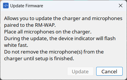
8.7. Procedure
-
Refer to the Charger wizard to pair the RM-WAP with the RM-WCH, and the RM-WAP with the microphone.
After pairing, leave the microphone mounted on the RM-WCH. -
Click the [Update] button.
Both the RM-WCH and the microphone will be updated.
While the update is in progress, the indicator on the device will flash white rapidly.
Do not disconnect the microphone from the RM-WCH until setup is completed.
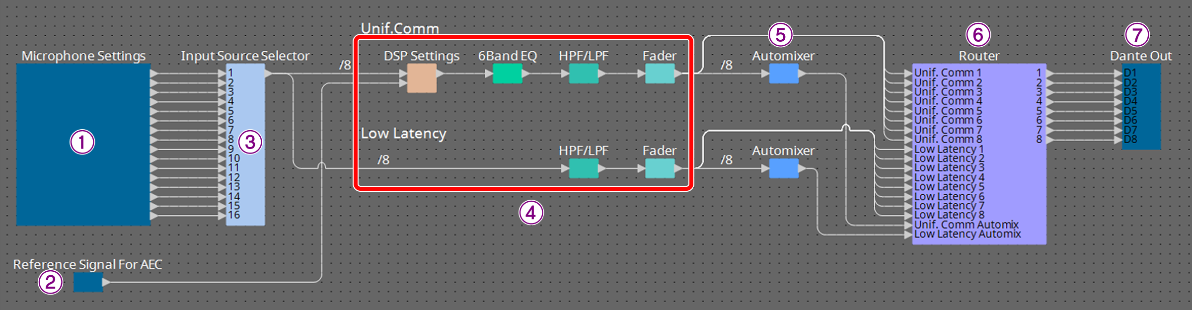
9. Component editor
Double-click a component on the device sheet to open the component editor.
This section describes the RM-WAP component editor and the dialog boxes and windows associated with the components.
| Number | Component name | Content | Link |
|---|---|---|---|
① |
Microphone Settings |
Set the basic functions of the microphone paired with the RM-WAP. |
|
② |
Reference Signal for AEC |
Display the reference signal level of the adaptive echo canceller. |
--- |
③ |
Input Source Selector |
Select the microphone input you want to enable. |
|
④ |
Unif.Comm/Low Latency |
Configure various DSP settings, including the adaptive echo canceller, noise reduction, and EQ. |
|
⑤ |
Automixer |
Automatically adjusts the audio signal level. |
|
⑥ |
Router |
Change the assignment of input channels to output channels. |
|
⑦ |
Dante Out |
--- |
--- |
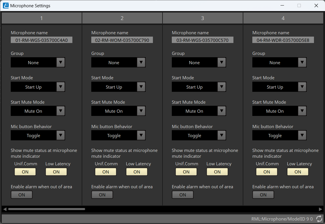
9.1. "Microphone Settings" component editor
Set the basic functions of the microphone paired with the RM-WAP.
-
Name
The name of the microphone. The name can be changed. -
Group
This parameter will be effective when used in combination with the RM-CR. For details, refer to "RM-W Web GUI Device Manager Operation Guide."If you are using Mic Mute Group of the DME series control component, set None. -
Start Mode
Select whether the microphone will go into standby mode when it is started. -
Start Mute Mode
Select whether the microphone will be turned on or off when it is started. -
Mic Button Behavior
Sets how to operate the Mic button.-
Toggle
Touching the Mic button will toggle the microphone between on and off. -
Push to talk
The microphone will be turned on only while you are touching the Mic button.
Transmission cannot be concurrently performed by multiple devices. -
Disable
Disables operation with the Mic button.
-
-
Show mute status at microphone mute indicator
When this function is turned on (normal), the microphone can be toggled between on and off by using the mute button or operating from ProVisionaire Design. The indicator will turn green when the microphone is on and turn red when the microphone is off.
When this function is turned off, the indicator color will change when you use the mute button or operate from ProVisionaire Design. However, the microphone status will always be on regardless of the indicator color. -
Enable alarm when out of area
Select whether the Mic indicator flashes when the microphone is out of the DECT connection range.
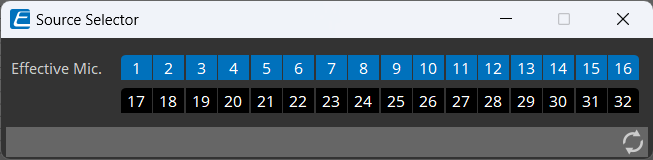
9.2. "Input Source Selector" component editor
Select the microphone input you want to enable.
-
Effective Mic.
The channel number of the active microphone input is displayed in blue.
The maximum number of microphones that can be enabled is 8 for the RM-WAP-8 and 16 for the RM-WAP-16.
9.3. "Unif.Comm/Low Latency" component editor
Configure various DSP settings, including the adaptive echo canceller and noise reduction.
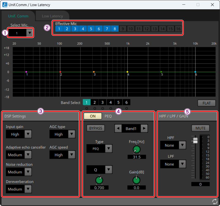
① Select Mic.
Select the microphone to edit. Only microphones enabled in the "Input Source Selector" component editor can be selected.
②Effective Mic.
Shows the microphones enabled in the "Input Source Selector" component editor.
For editing, use the "Input Source Selector" component editor.
③ DSP Settings (Unif.Comm only)
-
Input gain
Sets the input gain for the microphone.
OFF(0 dB)、LOW(6 dB)、MEDIUM(12 dB)、HIGH(18 dB) -
Adaptive echo canceller
This function removes diffraction of sound from speakers, echoes due to reflections from walls, and constant noise of air conditioning or other sources, which can be problematic during remote conferences.-
Off: Disables the echo canceller. Select this setting when using an echo canceller of a conferencing application or external device.
-
Low: Suppresses echoes while maintaining the quality of the original audio.
-
Medium: This setting provides well-balanced sound quality and echo cancellation strength.
-
High: Applies strong echo cancellation. Select this setting if the room has a long reverberation time or is prone to echoes.
-
-
Noise reduction
Select the strength of noise reduction for stationary noise.-
Off: Disables the noise reduction. Select this setting when using noise reduction of a conferencing application or external device.
-
Low: Suppresses stationary noise while maintaining the quality of the original audio.
-
Medium: This setting provides well-balanced sound quality and noise reduction strength.
-
High: Applies strong noise reduction. Select this setting for rooms with loud, stationary noise from large fans or air conditioning systems.
-
-
Dereverberation
This function makes the audio clearer by subtracting reverberation components from audio that contains the reverberation components. Select the strength of the reverberation removal.-
Off: Disables the reverberation suppression function.
-
Low: Select this setting for rooms with a short reverberation time.
-
Medium: A setting that can be used in normal environments. This setting provides well-balanced sound quality and reverberation suppression strength.
-
High: Applies strong reverberation suppression. Select this setting for rooms with a long reverberation time, such as a glass-walled room.
-
-
AGC type
AGC (Auto Gain Control) is a function that automatically adjusts the output gain to stabilize the audio level. This function increases the volume level of soft voices and decreases the volume level of loud voices. Select the strength of the AGC.-
Off: Disables AGC. Select this setting if you want to disable automatic volume control or use a different automatic volume control of a conferencing application or external device.
-
Low: This setting provides well-balanced volume changes.
-
High: Applies strong AGC.
-
-
AGC speed
Select the speed at which the AGC reacts to volume changes.-
Low: Well-balanced reaction speed.
-
High: Quickly reacts to volume changes.
-
④ PEQ (Unif.Comm only)
Adjusts the 6-band EQ. For details, refer to "ProVisionaire Design Component Guide."
⑤ HPF/LPF/GAIN
Sets the HPF, LPF, or GAIN.
9.4. "Automixer" component editor
This editor automatically adjusts the audio signal level.
First, select the automatic adjustment processing method (Gain Sharing or Gating) from the [Type] list box.
-
Gain Sharing
Adjusts the gain of each channel so that the sum of the gains of multiple input audio signals is always equal. -
Gating
Determines whether the input audio of the channel is to be processed based on the input level threshold.

Gain Sharing
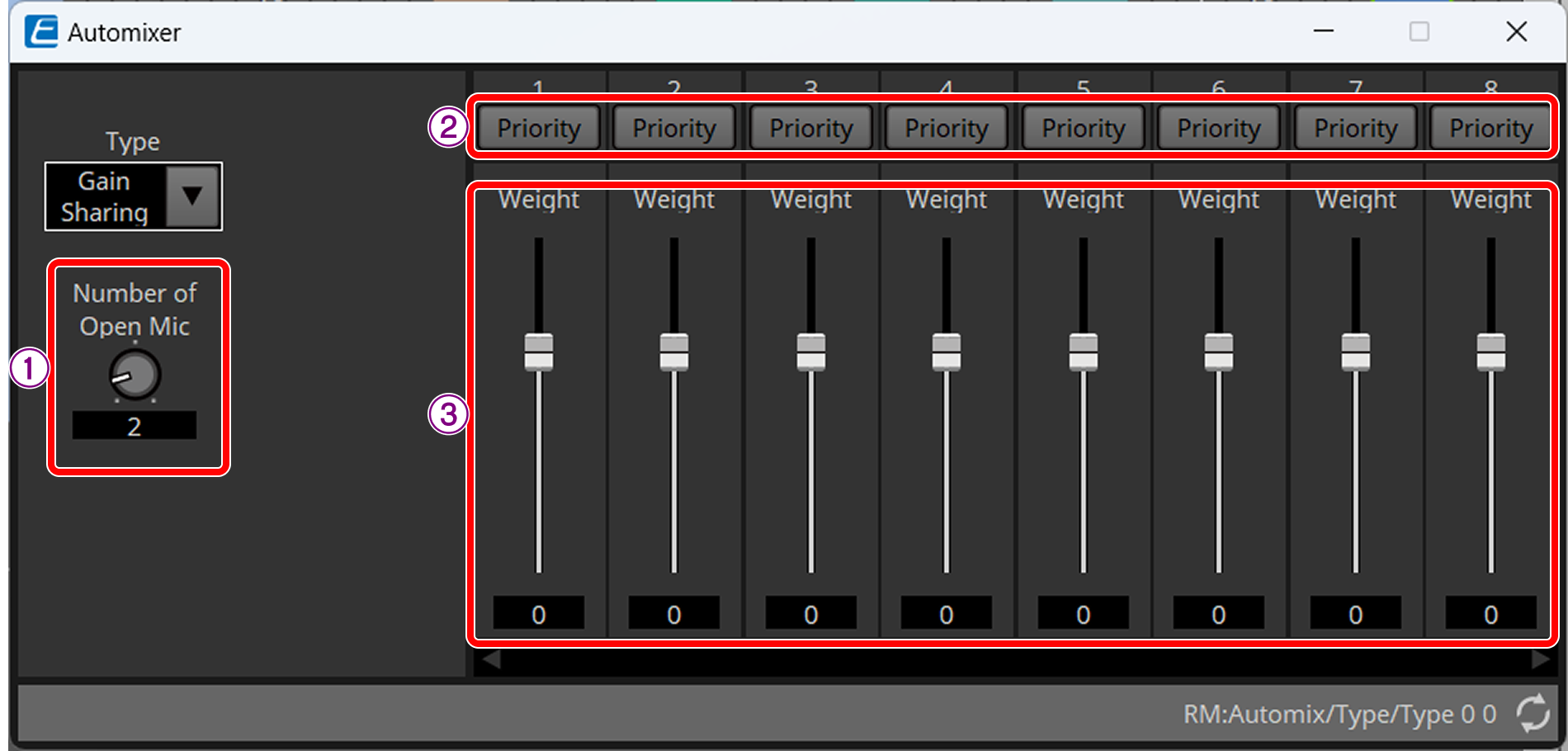
① Number of Open Mic
Sets the number of enabled microphones that will be included in the auto mixing at simultaneous speech.
② [Priority] button
This is the microphone priority setting. When a microphones is set as a priority microphone, this setting will be turned on regardless of the number of open microphones.
③ Weight fader
Sets the weighting of the auto mixing level. Specifying the higher value will increase the volume level after auto mixing. Input range: -30 to 15 dB
Setting [Weight] has no effect on channels with [Priority] set to ON.
Gating
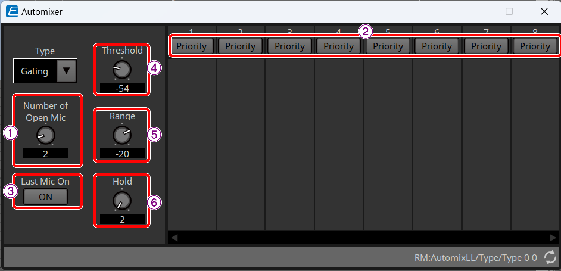
① Number of Open Mic
Sets the number of enabled microphones that will be included in the auto mixing at simultaneous speech.
② [Priority] button
This is the microphone priority setting. When the signal level of the input channel set as the priority microphone exceeds the threshold, the gate will open regardless of the current number of open microphones.
③ Last Mic On
When this settings is set to ON, the gate will remain open if the signal level of the microphone channel that last opened the gate falls below the threshold.
④ Threshold
The signal level at which the gate opens.
⑤ Range
The gain to be applied when the gate is closed.
⑥ Hold
The time within which the gate remains open after the signal level falls below the threshold.
9.5. "Router" component editor
Change the assignment of input channels to output channels.
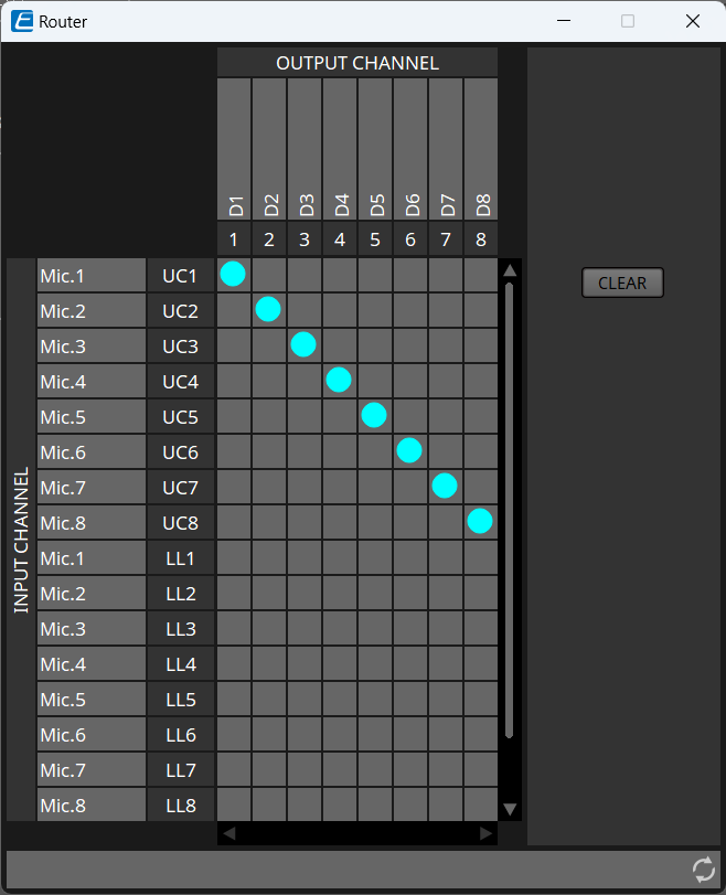
The RM-WAP-8 is 18 In and 8 Out. The RM-WAP-16 is 34 In and 16 Out.
INPUT CHANNEL shows the channel set in the "Input Source Selector" component editor.