Wall Mount Controller MCP2
1. Overview
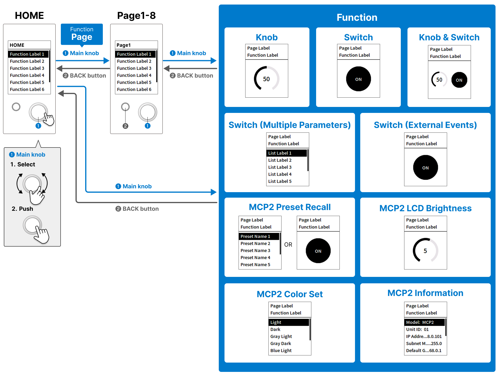
The MCP2 is a wall mount controller that can be attached to a wall. By operating the main knob and BACK button, you can switch the pages displayed on the LCD screen and control the devices on the parameter operation screen.
The page structure can be customized, with up to two levels (including the home screen), each level with up to eight items and a total of 64 parameters that can be controlled. Three setting modes can be selected depending on the number of page levels and the number of parameters to be controlled.
Control is performed by pressing (Switch) or rotating (Knob) the main knob.
If your system includes a DME, you can control peripheral devices by using Conductor or Trigger. To directly control an external device, specify the control protocol in External Event.
You can also configure general-purpose settings for the main unit, such as the Sleep setting, on the Utility screen.
2. "Project" sheet
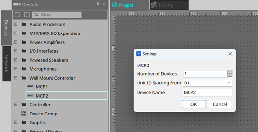
This is the sheet where you place devices. When placing a device, the Settings screen below will appear.
-
Number of Devices
Select the number of MCP2 devices to be placed on the sheet. -
Unit ID Starting From
You can select the starting number for the Unit IDs of devices. -
Device Name
You can view and edit the device name.
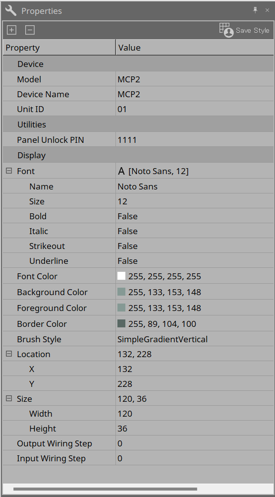
2.1. "Properties" area
You can view and edit MCP2 information.
-
Utilities
-
Panel UnlockPIN
The code to unlock the panel. It is a four-digit number.
You can disable and enable the PIN and set the sleep time in the Utility tab of the component editor.
-
3. Mode types
The MCP2 has the following three modes. Select the type according to your usage situation.
In the MCP2, each assigned function is called a Function.
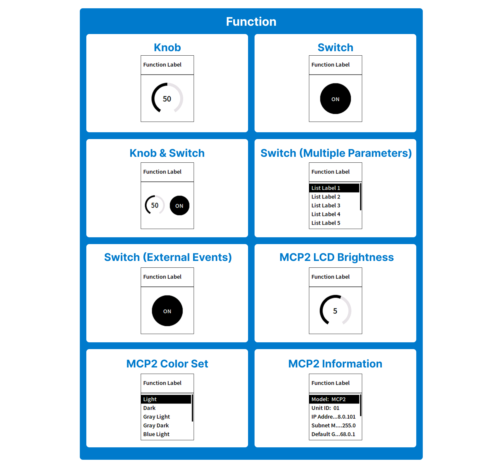
3.1. Single Function mode
This mode is for users who want to assign only one function for simple use. Assign only one Function to the HOME screen. The screen image when each Function is assigned is shown below.
3.2. Multi-function mode
This mode is for users who want to have some functions. You can assign up to eight Functions to the HOME screen. The assigned Functions are displayed in a list on the HOME screen. You can select them with the main knob and push the knob to transition to the Function screen.
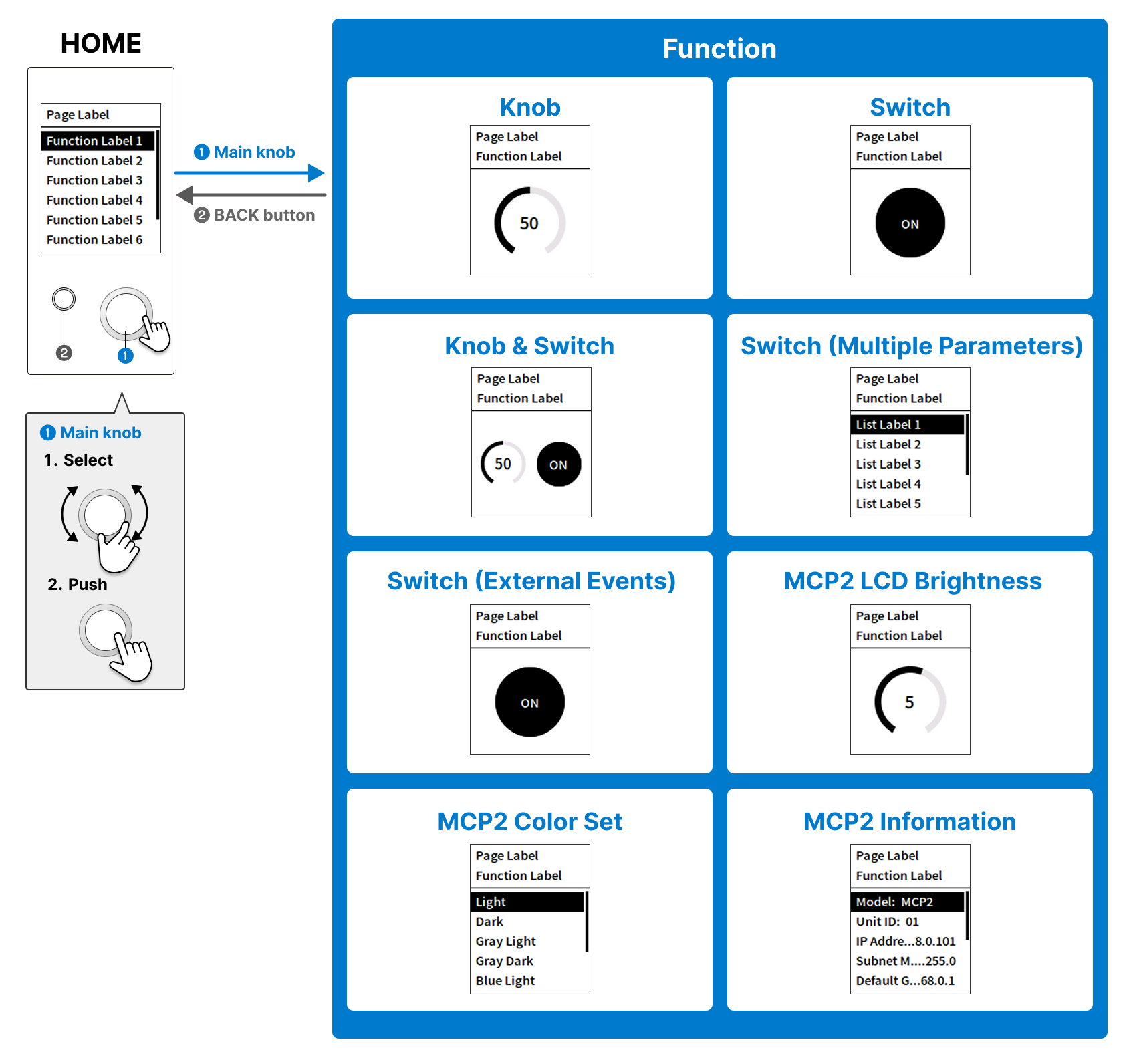
3.3. Multi-page mode
This mode is for users who want to assign many functions using a hierarchical structure. You can assign up to eight Functions to the HOME screen. Furthermore, you can transition to other pages by assigning the Function "Page" to the HOME screen. The maximum number of pages that can be transitioned from the HOME screen is eight pages. You can also assign up to eight Functions to each page.
Moreover, the Function “MCP2 Preset Recall” is provided, so you can store and recall up to eight presets.
4. Workflow
Preparation
There are the following two ways to control devices with the MCP2.
-
Conductor
By controlling the DME’s Conductor component with the MCP2, the DME itself and peripheral devices can be controlled. First, you need to configure the settings in the Conductor component editor. For details, refer to "Conductor" in "ProVisionaire Design Component Guide." -
External Event
The MCP2 issues TCP/UDP commands to control external devices.
Workflow
-
Double-click the MCP2 placed on the “Project” sheet.
The component editor appears. -
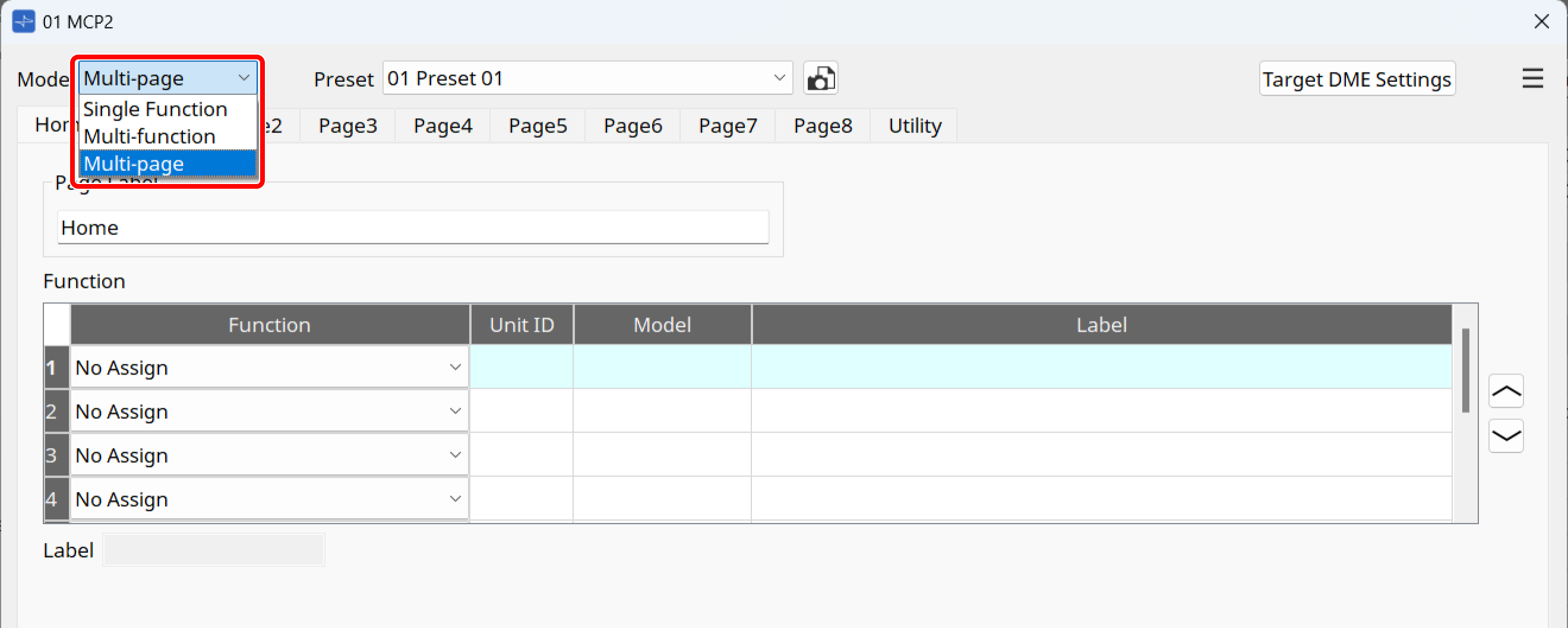
Select the mode in the Mode list box.
For the differences between respective modes, refer to "Mode types."
-
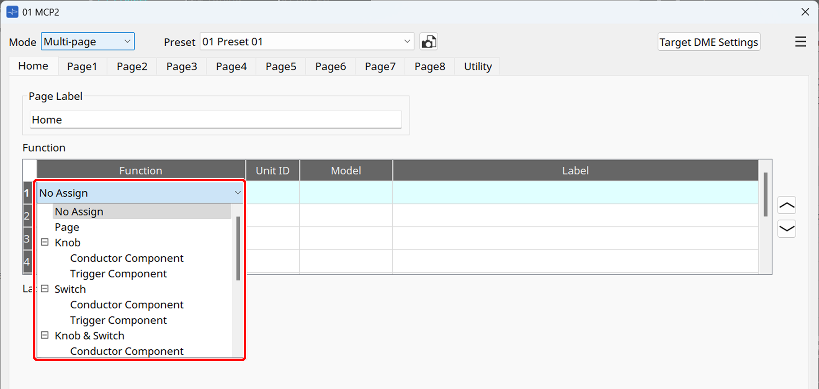
Assign the desired settings in the Function area.
For details on each Function to be assigned, refer to "Function."
-
Once you have completed the assignment, press the [Apply] button to confirm the settings in Single Function mode and Multi-function mode.
-
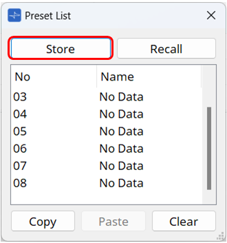
In Multi-page mode, save the preset.
Click the button and store the preset in the Preset List dialog box that appears.
| In Multi-page mode, changes will not be reflected unless the preset is stored. Be sure to store any changes you make. |
-
Go online and import the settings to the MCP2.
For information about online, refer to "Online and synchronization."
In Single Function mode or Multi-function mode, the processes are completed here. Operate the MCP2 and check that it functions properly.
-
In Multi-page mode, once you have finished importing the settings, recall a desired preset in the Preset List dialog box.
When the preset is recalled, the settings will be reflected in the MCP2. Operate the MCP2 and check that it functions properly.
5. Component editor
The editor will appear when you double-click the MCP2 placed on the "Project" sheet.
You can assign functions to the MCP2 and make general-purpose settings.
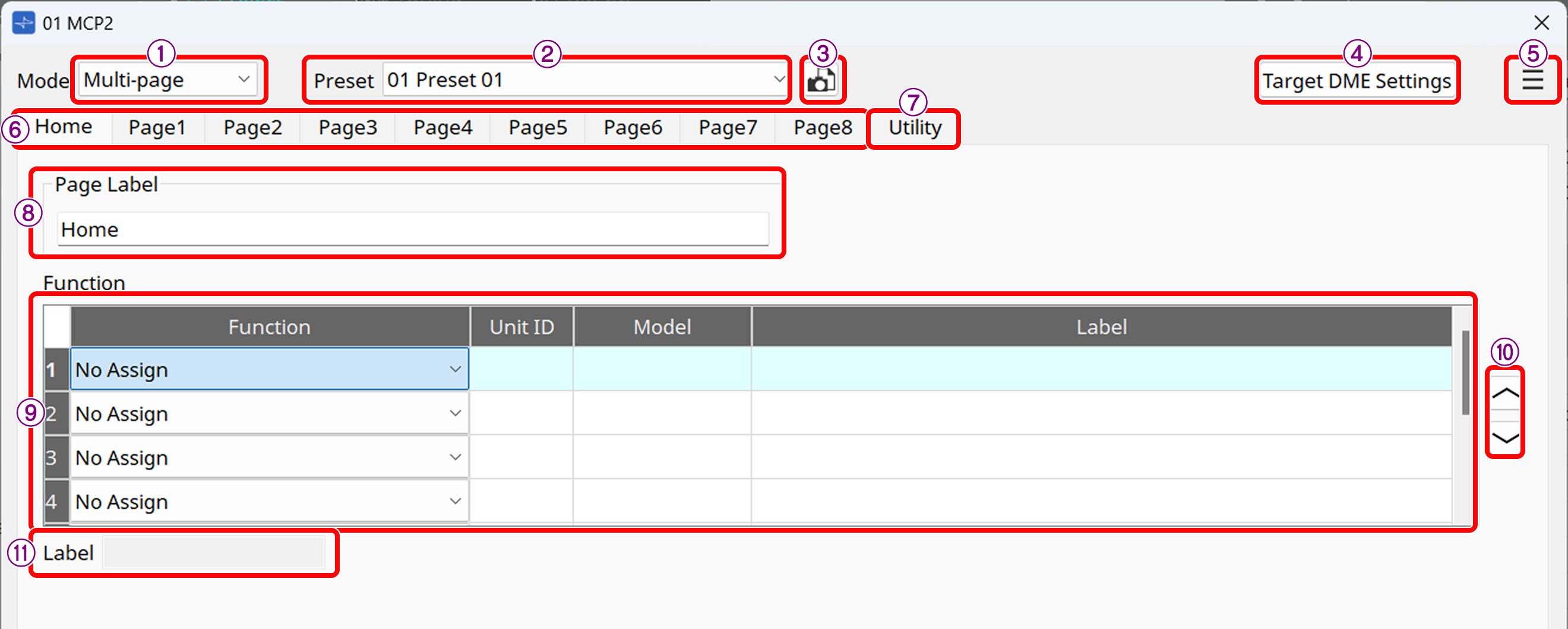
Multi-page mode
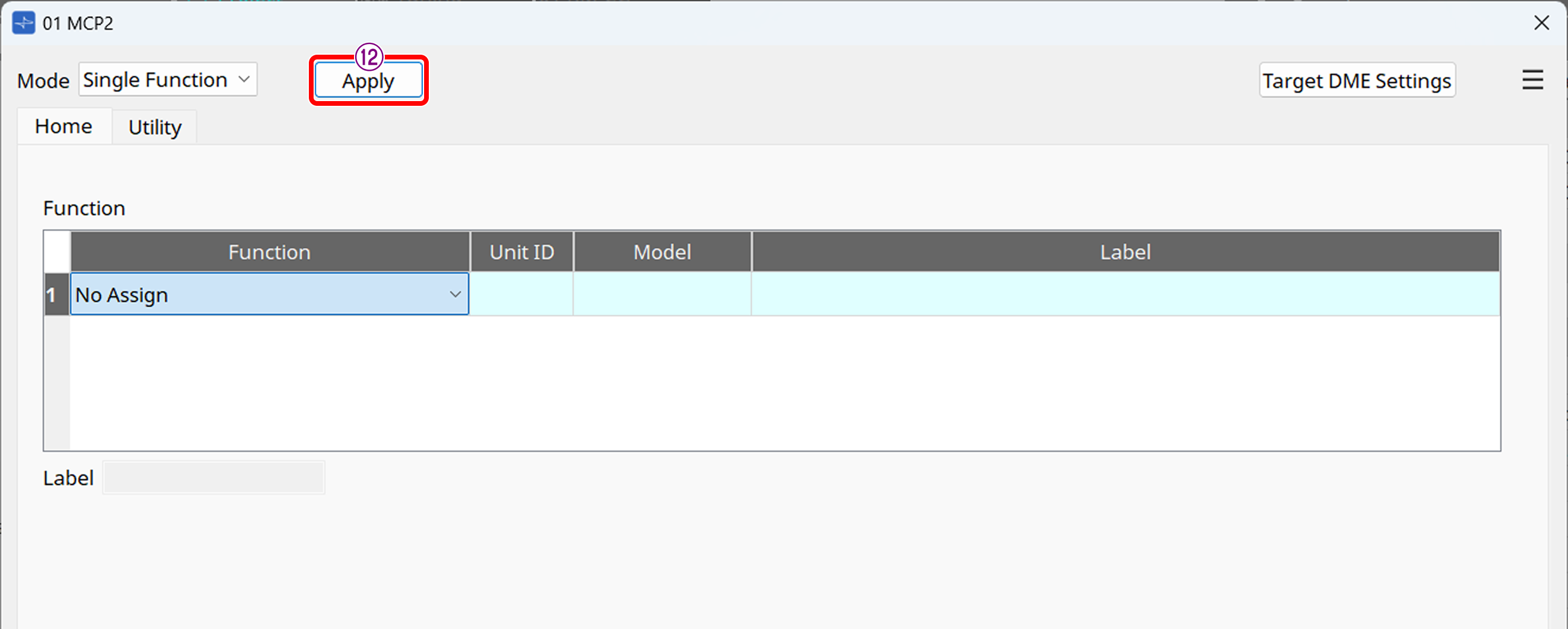
Single Function mode
① [Mode] list box
Switches the mode. For details on each mode, refer to "Mode types."
② Preset list (Multi-page mode only)
Select a preset to recall it.
③ [Preset] button (Multi-page mode only)
Click this button to open the "Preset List" dialog box.
④ [Target DME Settings] button
Click this button to open the “Target DME Settings” dialog box.
⑤ [Menu] button
Click this button to display the menu.
Clear Page: Clears the Functions assigned to the currently-displayed page.
Clear All Pages: Clears the Functions assigned to all pages.
⑥ Home/Page 1 to 8 tabs
Switches the page to be set. In Single Function mode and Multi-function mode, only the Home page is available. In Multi-page mode, there are Page 1 to Page 8.
⑦ Utility tab
Configure the MCP2 settings, including the display brightness, background color, back key, and sleep.
For details, refer to "Utility tab."
⑧ Page Label (Multi-page mode and Multi-function mode only)
Set the page name.
⑨ Function area
Select the function to assign to the page. For details on each function, refer to "Function."
⑩ Swap button (Multi-page mode and Multi-function mode only)
Swaps the selected row in the Function area with the row above or below.
⑪ [Label] text box
Enter the name to be given to the Function. This label will appear on the MCP2 display.
⑫ [Apply] button (Multi-function mode and Single Function mode only)
Applies the settings.
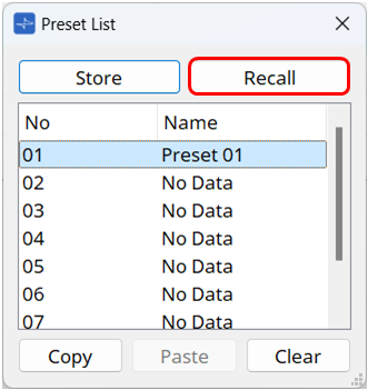
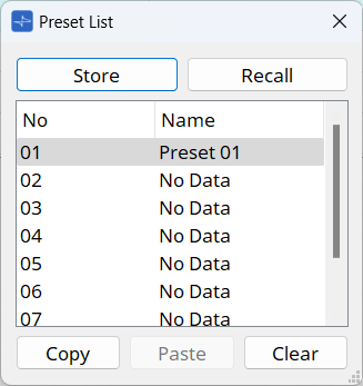
5.1. "Preset List" dialog box
This dialog box can be displayed with the ![]() button in the MCP2 component editor.
button in the MCP2 component editor.
You can save up to eight MCP2-related settings as "presets."
Presets can be recalled from the MCP2 itself or from an external device. They can also be recalled from other MCP2s.
-
[Store] button
Saves the settings of [Home], [Page 1] to [Page 8], and [Utility] to a preset. -
[Recall] button
Recalls the selected preset.
The settings are deployed to [Home], [Page 1] to [Page 8], and [Utility].
Recalling a preset while online will also change the panel settings of the main unit. -
[Copy] button
Copies the selected preset. -
[Paste] button
Pastes the copied preset into the currently-selected preset. -
[Clear] button
Clears the selected preset.
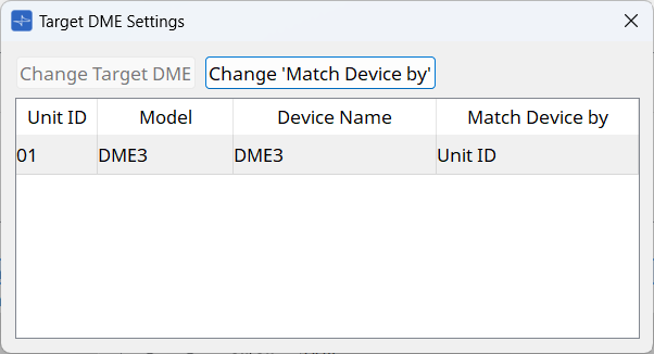
5.2. "Target DME Settings" dialog box
This dialog box can be displayed with the [Target DME Settings] button in the MCP2 component editor.
In this dialog box, you can replace an assigned DME and change how the MCP2 discovers the DME.
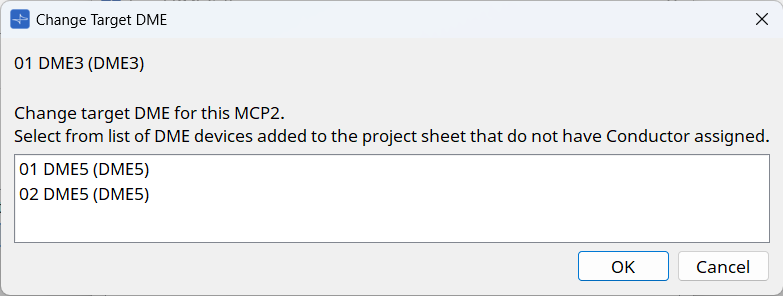
Replacing an assigned DME
If the DME assigned to the Functions "Knob," "Switch," "Knob & Switch," or "Switch(Multiple Parameters)" no longer exists due to reasons such as "changing the Unit ID," or if you want to replace DME3 with DME5, you can replace it with another DME.
The list shows DMEs assigned to the Functions "Knob," "Switch," "Knob & Switch," and "Switch(Multiple Parameters)."
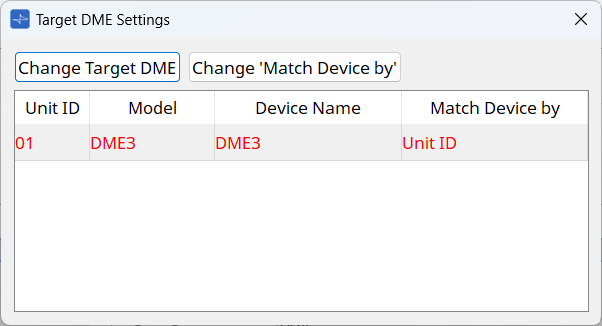
DMEs that have been deleted from the project sheet after being assigned or DMEs whose Unit ID has changed are displayed in red.
Select the DME to be replaced and press the [Change Target DME] button.
In the dialog box that appears, select the DME to replace it with. Click the [OK] button to replace the DME in the preset with the DME you are editing.
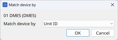
Changing how the MCP2 discovers the DME
Click the [Change 'Match Device by'] button to display the dialog box.
You can change the search method for the selected DME to either Unit ID or IP address.
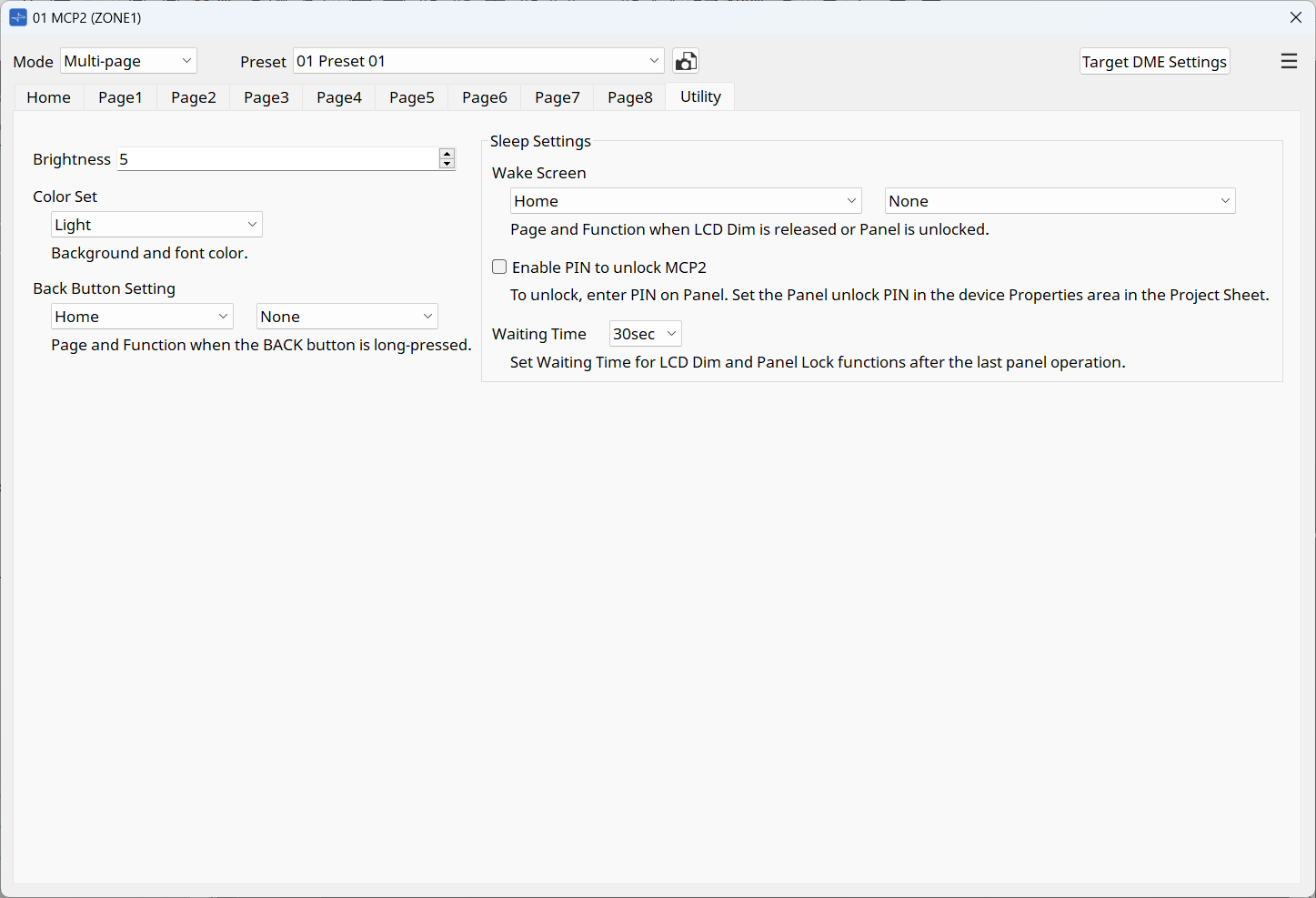
5.3. "Utility" tab
The screen can be displayed from the [Utility] tab in the MCP2 component editor.
This screen allows you to configure general-purpose settings for the MCP2 main unit. These settings can be specified for each preset.
-
Brightness
You can change the brightness of the display. The larger number will increase the brightness. -
Color Set
You can change the background and font color. -
Back Button Setting
Specifies the page that will be displayed when you press and hold the BACK button for 2 seconds.
Specify the page with the check box on the left, and the Function No. in the check box on the right. -
Sleep Settings
-
Wake Screen
Specifies the page that will be displayed when you cancel the sleep or locked state.
Specify the page with the check box on the left, and the Function No. in the check box on the right. -
Enable PIN to unlock MCP2
If you select the check box, you will be required to enter a PIN when canceling the locked state.
Set the PIN in the Properties area of the project sheet. -
Waiting Time
Sets the time from the last operation on the MCP2 until it goes into sleep or locked state.
-
6. Function
Each function that can be assigned to the MCP2 is called a Function. Select the Function to assign in the Function list box of the MCP2 component editor. In Multi-page mode and Multi-function mode, you can assign up to eight Functions to one page. In Single Function mode, you can assign only one Function to the screen.

The types of Functions are as follows:
| Function | Overview |
|---|---|
Transitions to another page. |
|
Knob |
Continuously controls parameters and other settings of peripheral devices by rotating the main knob of the MCP2. |
Switch |
Recalls a preset of a peripheral device or calls a fixed parameter value by pressing the main knob of the MCP2. |
Knob & Switch |
Arranges operations to be executed by rotating or pressing the main knob of the MCP2 side-by-side to control peripheral devices. |
Switch(Multiple Parameters) |
Lists the control items on the screen. Rotate the main knob of the MCP2 to select the control item and press the knob to execute the item. |
Sends TCP/UDP commands to control external devices. |
|
Recalls a preset of the MCP2. |
|
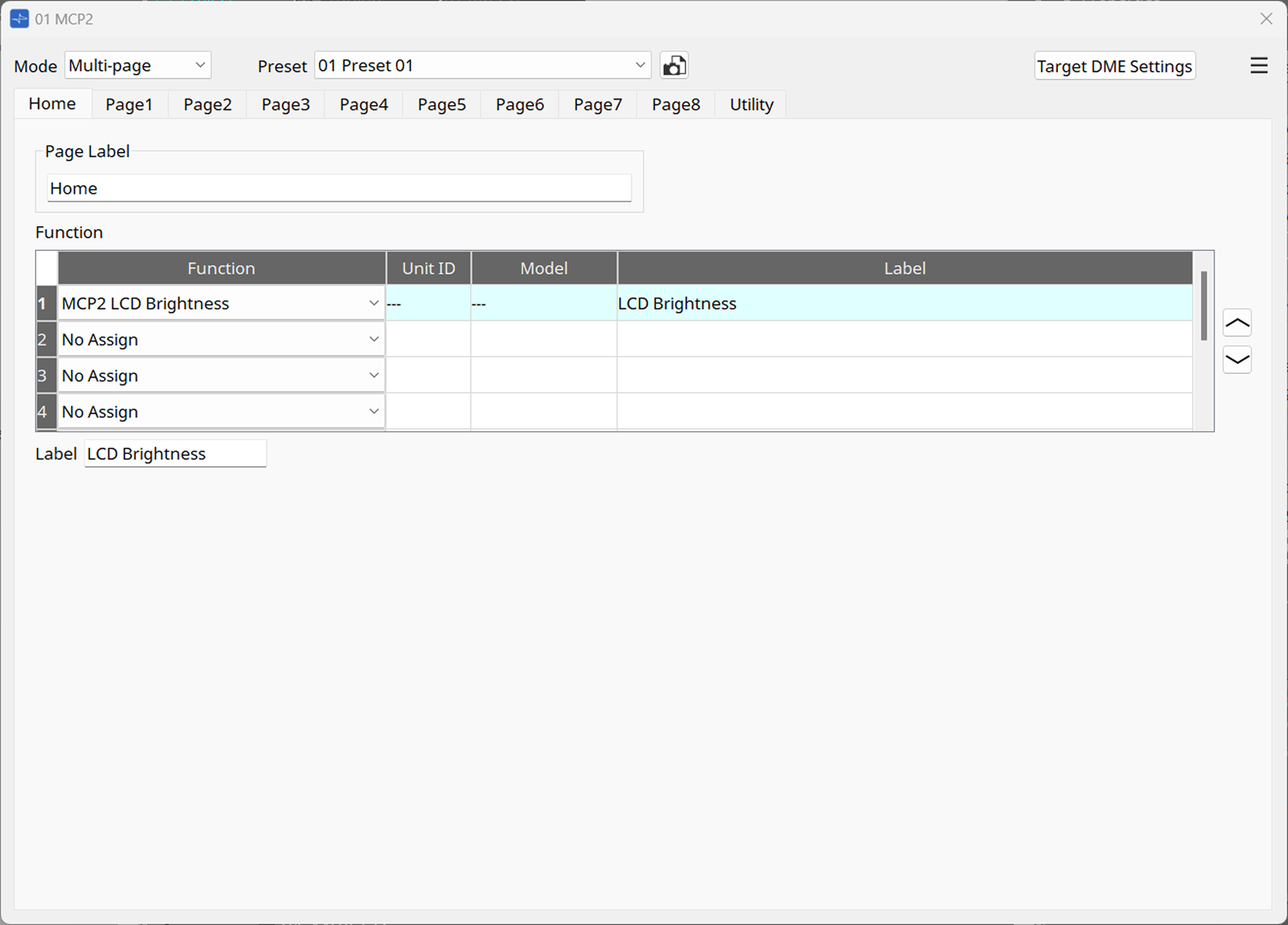
Adjust the screen brightness. |
|
Sets the screen color. |
|
Shows the main unit information. |
-
For details on "Conductor Component" and "Trigger Component," refer to "Conductor" in "ProVisionaire Design Component Guide."
6.1. Page
This function transitions the page from the Home page to another page. The function is only displayed on the Home page in Multi-page mode.
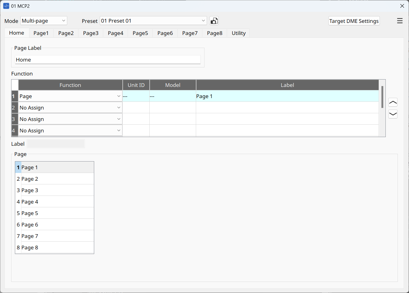
Select the page (1 to 8) you want to transition to from the Home page.
The right column shows the Page Label for each page.
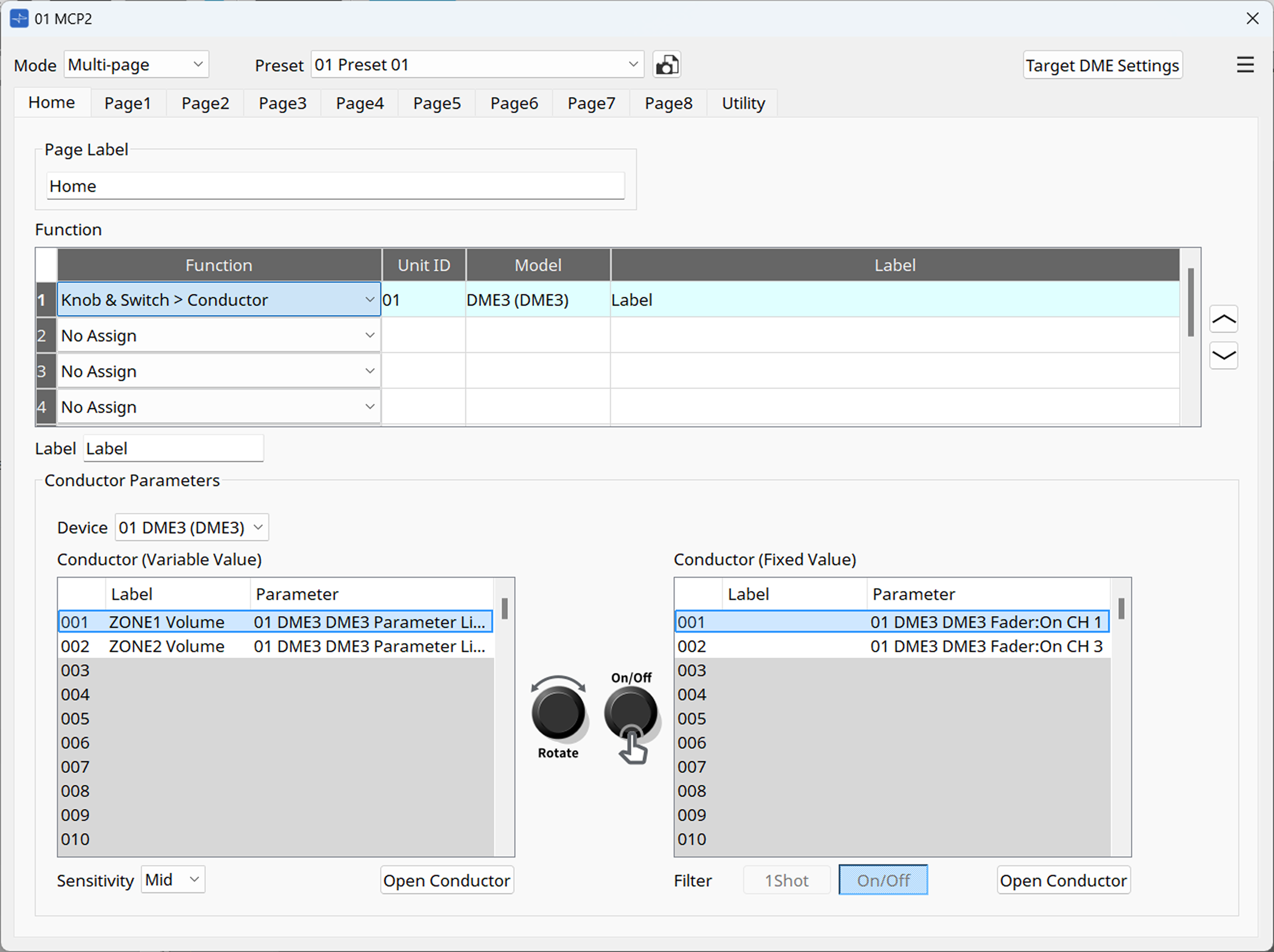
6.2. Knob
By rotating the main knob of the MCP2, you can control the parameters of peripheral devices via the DME’s Conductor component.
To assign a Conductor component item, select "Conductor Component."
To assign an Input Trigger component item, select "Trigger Component."
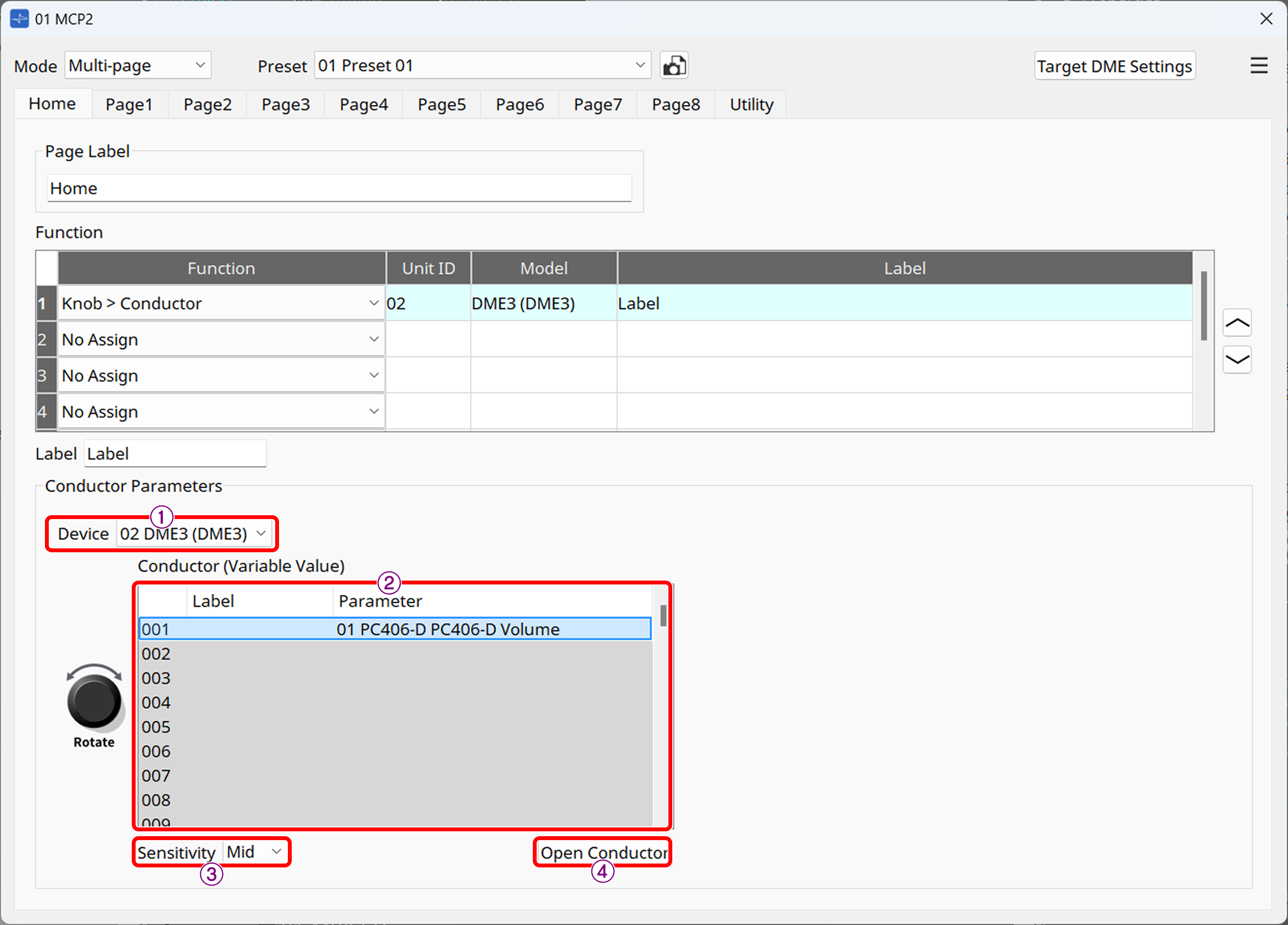
① [Device] list box
Select the DME that will execute the Conductor function.
② List
For "Conductor Component," the list numbers (1 to 256) and labels of the Variable Value components for the DME’s Conductor, and the parameters to be controlled will be displayed. For "Trigger Component," the port numbers of the for Variable Value components will be displayed. Select the number you want to assign.
| To display the assigned item in the list, you must register it in the Conductor component editor beforehand. For details on the Conductor function, including how to register, refer to "Conductor" in "ProVisionaire Design Component Guide." |
③ [Sensitivity] list box
Sets the sensitivity to the changes in the knob rotation.
④ [Open Conductor] button
Opens the Conductor component editor for the DME selected in ①.
6.3. Switch
By pressing the main knob of the MCP2, you can control the fixed values for the parameters, buttons, and presets of peripheral devices via the DME’s Conductor component.
To assign a Conductor component item, select "Conductor Component."
To assign an Input Trigger component item, select "Trigger Component."
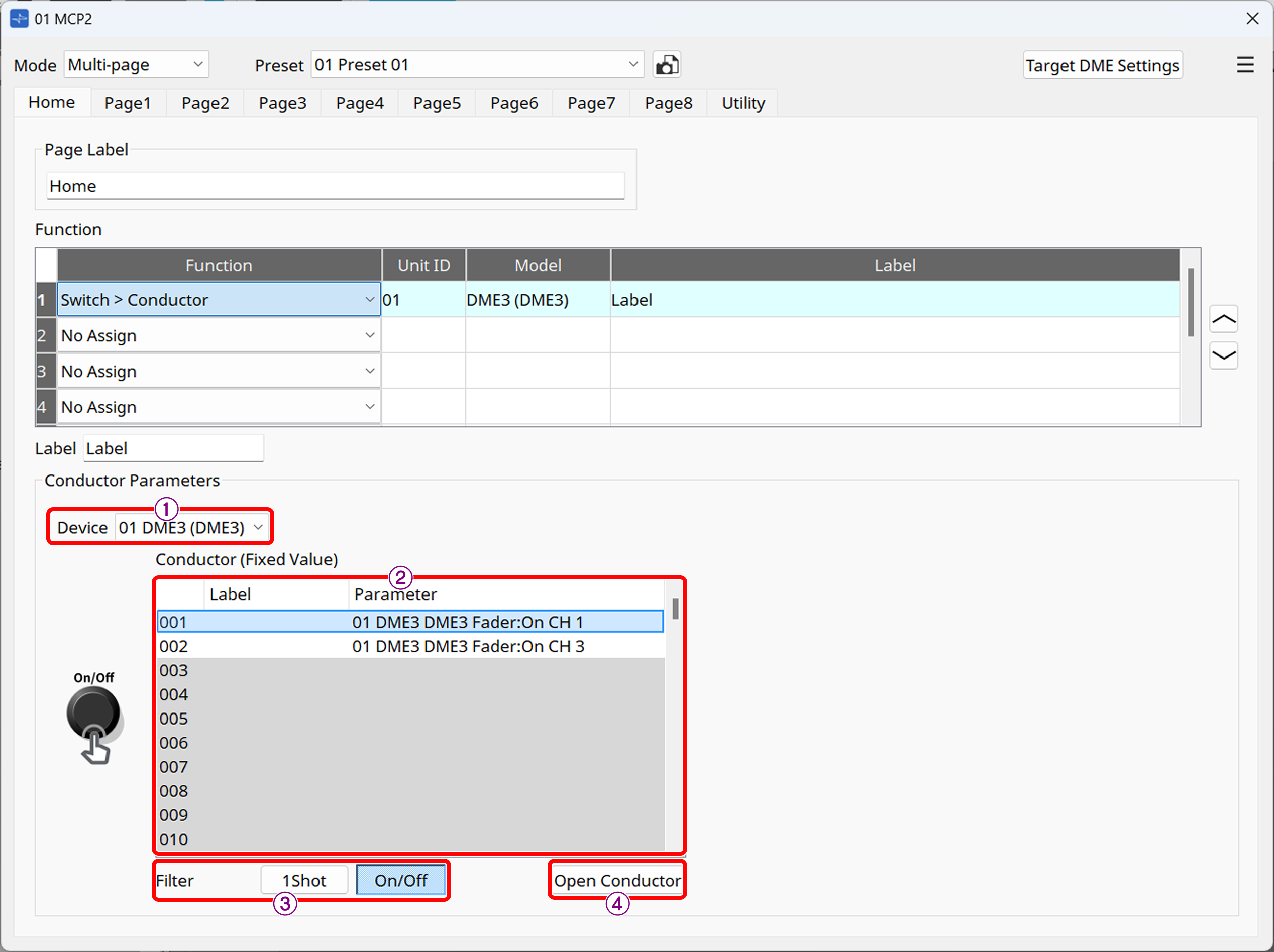
① [Device] list box
Select the DME that will execute the Conductor function.
② List
For "Conductor Component," the list numbers (1 to 256) and labels of the Fixed Value components for the DME’s Conductor, and the parameters to be controlled will be displayed. For "Trigger Component," the port numbers of the for Fixed Value components will be displayed. Select the number you want to assign.
| To display the assigned item in the list, you must register it in the Conductor component editor beforehand. For details on the Conductor function, including how to register, refer to "Conductor" in "ProVisionaire Design Component Guide." |
③ [Filter] button
-
1Shot
Shows locations in the Fixed Value component of Conductor, where presets, snapshots, and fixed values of parameters are assigned. -
On/Off
Shows locations in the Fixed Value component of Conductor, where parameters to be toggled between on and off are assigned.
④ [Open Conductor] button
Opens the Conductor component editor for the DME selected in ①.
6.4. Knob & Switch
By assigning an item to be executed to the rotating or pressing operation of the MCP2’s main knob, you can control peripheral devices via the DME’s Conductor component.
To assign a Conductor component item, select "Conductor Component."
To assign an Input Trigger component item, select "Trigger Component."
6.5. Switch(Multiple Parameters)
This function shows the list numbers and labels of up to 16 parameters and snapshots registered in a MCP2’s page by using Conductor. To execute the Conductor function, select the item in the list by rotating the main knob of the MCP2 and push the knob.
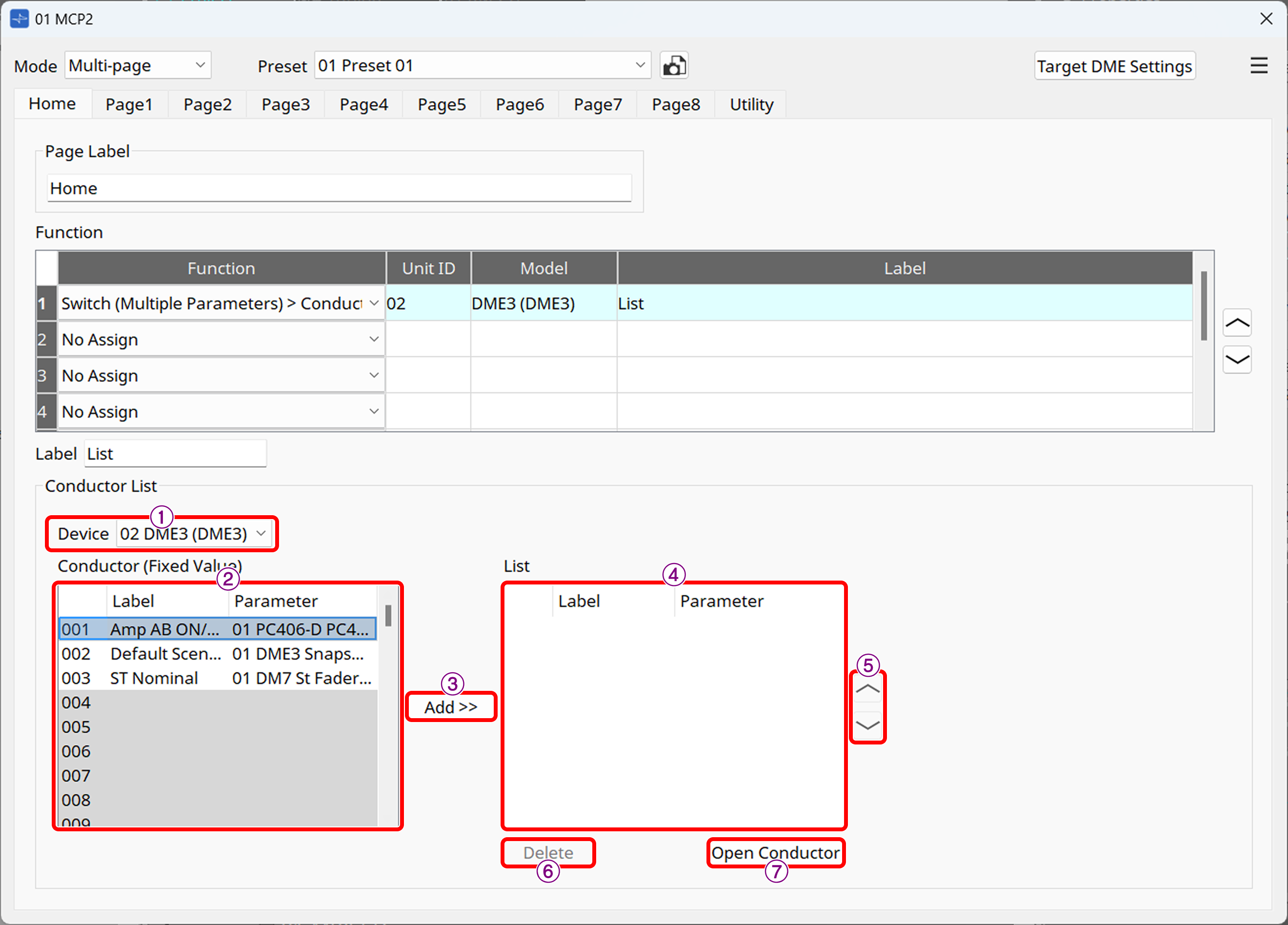
① [Device] list box
Select the DME that will execute the Conductor function.
② List
The list numbers (1 to 256) and labels of the Fixed Value components for the DME’s Conductor, and the parameters to be controlled will be displayed. The list numbers of up to 16 Conductor components can be registered in one page.
| To display the assigned item in the list, you must register it in the Conductor component editor beforehand. For details on the Conductor function, including how to register, refer to "Conductor" in "ProVisionaire Design Component Guide." |
③ [Add>>] button
Adds the item selected in the list on the left to the list displayed on the MCP2.
④ List
This list is displayed on the MCP2.
⑤ Swap button
Moves the order of the selected item up or down in the list.
⑥ [Delete] button
Deletes the item selected in the list.
⑦ [Open Conductor] button
Opens the Conductor component editor.
6.6. Switch(External Events)
The MCP2 sends TCP/UDP commands to control a desired device.
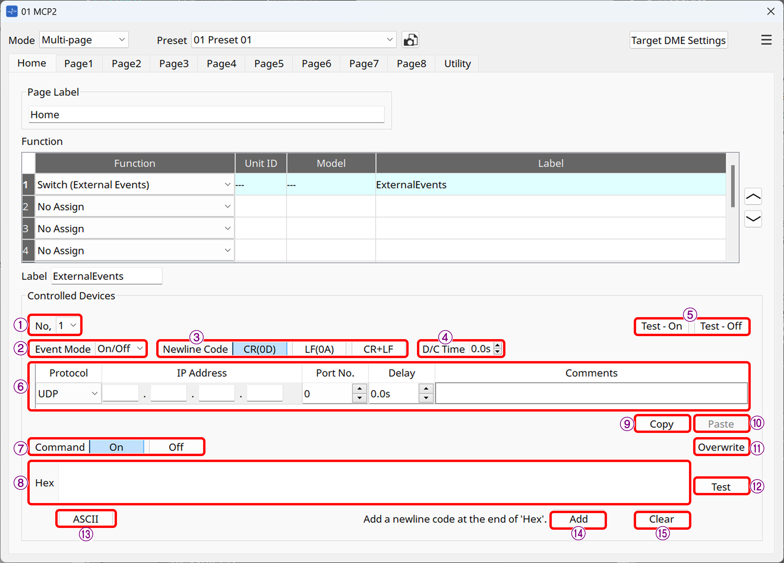
① [No.] list box
Select the command to edit. Up to five commands can be set.
② [Event Mode] list box
On/Off: On and Off commands are sent alternately each time the function is executed.
1shot: A command is issued when the button is pressed.
③ [Newline Code] button
Select the line break code to be entered when a line break is entered in the [Hex] field or at the end of a command using the [Add] button. You can choose from CR(0D), LF(0A), and CR+LF.
④ [D/C Time] (TCP only)
Specifies the time until communication with the device is disconnected after a command is sent. If the device cannot be controlled properly, adjust the disconnection time.
⑤ [Test-ON] and [Test-Off] buttons
ProVisionaire Design will issue events 1 to 5 as configured.
⑥ Event area
-
Protocol: Select the protocol type between UDP and TCP.
-
IP Address: Specifies the send destination for the command.
-
Port No.: Specifies the send destination for the command. You can specify a value between 0 and 65535.
-
Delay: Specifies the time from the time the Function is executed until each command is issued. The maximum time is 60 seconds.
-
Comments: You can write a free comment as a note.
⑦ [Command] button
If "On/Off" is selected in Event Mode, set commands respectively for On and Off.
⑧ [Hex] field
Enter a hexadecimal command. The maximum size is 256 bytes.
⑨ [Copy] button
Copies the command settings.
⑩ [Paste] button
Pastes the copied command settings to commands for another No.
⑪ [Overwrite] button
When this button is turned on, the command entry in the [Hex] field will be the overwrite method at the cursor position. When it is turned off, the insert method will be enabled.
⑫ [Test] button
Sends a command to the device specified by ProVisionaire Design to confirm the command.
Use this button if the MCP2 is not available.
⑬ ASCII button
Enter a string in the text box in the dialog box that appears when you click this button, and then press Covert. The string will be converted to hexadecimal and displayed in the Hex field.
If Hex is entered before the dialog box opens, the hexadecimal number will be converted to a string and displayed.
When you press the Convert button, the line break code selected in New Line Code will be used.
| Even if 0D is embedded in the Hex when you open the dialog box, if LF is selected in New Line Code, 0D will be converted to 0A when you press Convert. |
⑭ [Add] button
Click this button to insert the line break code selected in [Newline Code] at the end of the command.
⑮ [Clear] button
Click this button to clear [Hex].
6.7. MCP2 Preset Recall
This function recalls a preset of the MCP2. It is only available in Multi-page mode.
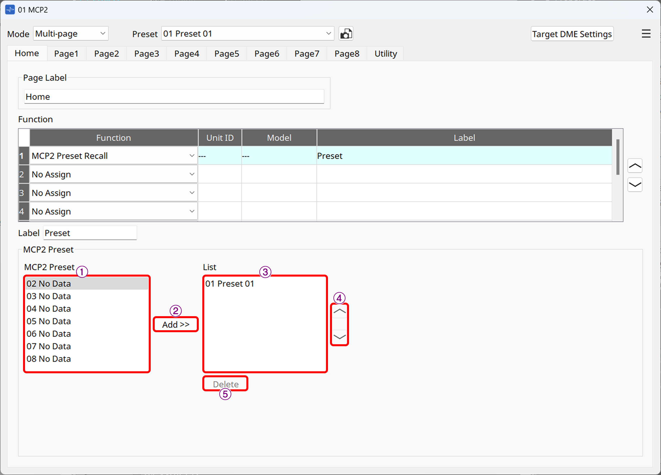
① MCP2 Preset
Shows the same MCP2’s presets as in the "Preset List dialog box."
② [Add>>] button
Adds the item selected in the list on the left to the list displayed on the MCP2.
③ List
This list is displayed on the MCP2. You can add up to 8 lists.
④ Swap button
Moves the order of the selected item up or down in the list.
⑤ [Delete] button
Deletes the item selected in the list.

6.10. MCP2 Information
This function displays the information on the MCP2 main unit.
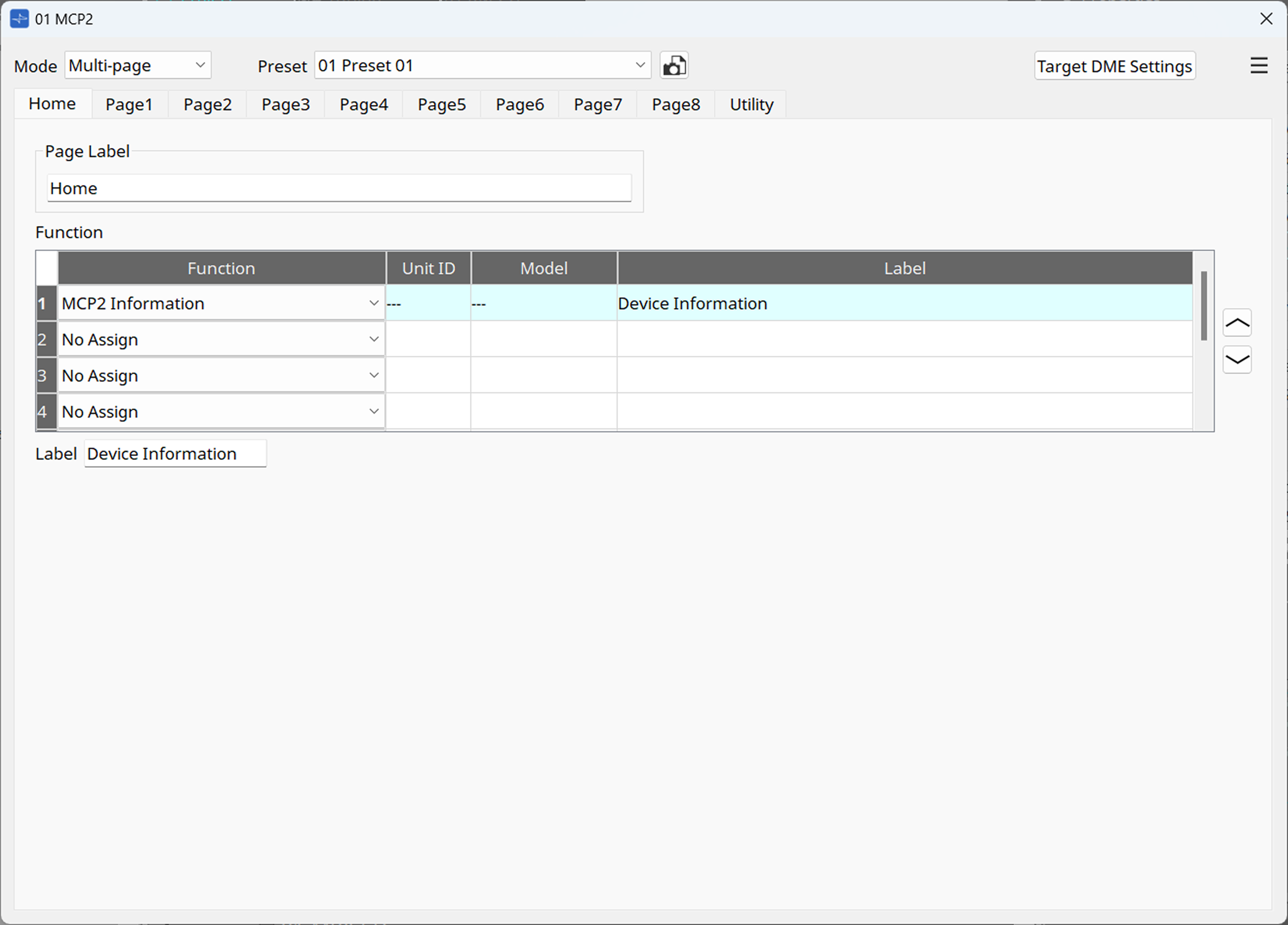
The following information is displayed on the MCP2 screen
・Model name
・Unit ID
・IP Address
・Subnet Mask
・Firmware Version
・Mac Address
・Serial No.