Controller CTL-BN1
1. Overview
The CTL-BN1 is a button-type controller that can be placed on a table or wall and is optimum for muting the microphone or recalling presets at hand. The simple design with only one button allows for intuitive and quick operation.
You can assign actions to each of the two states of the toggle operation. If your system includes a DME, you can control peripheral devices by using the DME’s Conductor. To directly control an external device, specify the control protocol in External Event.
2. "Project" sheet
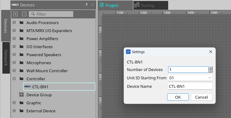
This is the sheet where you place devices. When placing a device, the Settings screen below will appear.
-
Number of Devices
Select the number of CTL-BN1 devices to be placed on the sheet. -
Unit ID Starting From
You can select the starting number for the Unit IDs of devices. -
Device Name
You can view and edit the device name.
2.1. "Properties" area
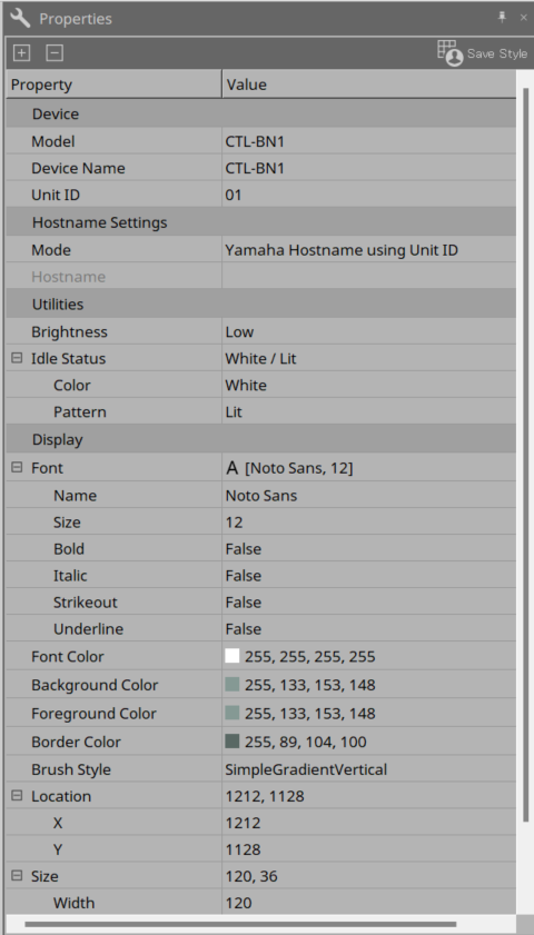
You can view and edit CTL-BN1 information.
-
Utilities
-
Brightness
The LED brightness setting. -
Idle Status
The LED settings for idle status.
Color: Specifies the color.
Pattern: Specifies the lighting pattern.
-
3. Workflow
Preparation
There are the following two ways to control devices with the CTL-BN1.
-
Conductor
By controlling the Fixed Value component of the DME’s Conductor with the CTL-BN1, the DME itself and peripheral devices can be controlled. You need to separately configure the settings in the Conductor component editor. For details, refer to "Conductor" in "ProVisionaire Design Component Guide." -
External Event
The CTL-BN1 issues TCP/UDP commands to control external devices.
Workflow
-
Double-click the CTL-BN1 placed on the “Project” sheet.
The “component editor” appears.
-
In the [Mode] list box of the component editor, select Conductor or External Event.
-
Configure various settings on the Conductor screen or External Event screen.
For details on each screen, refer to "Mode." -
Once you have finished configuring the settings, click the [OK] button to close the editor.
If the system is online, the setup is completed here. Check that the buttons function properly.
4. Component editor
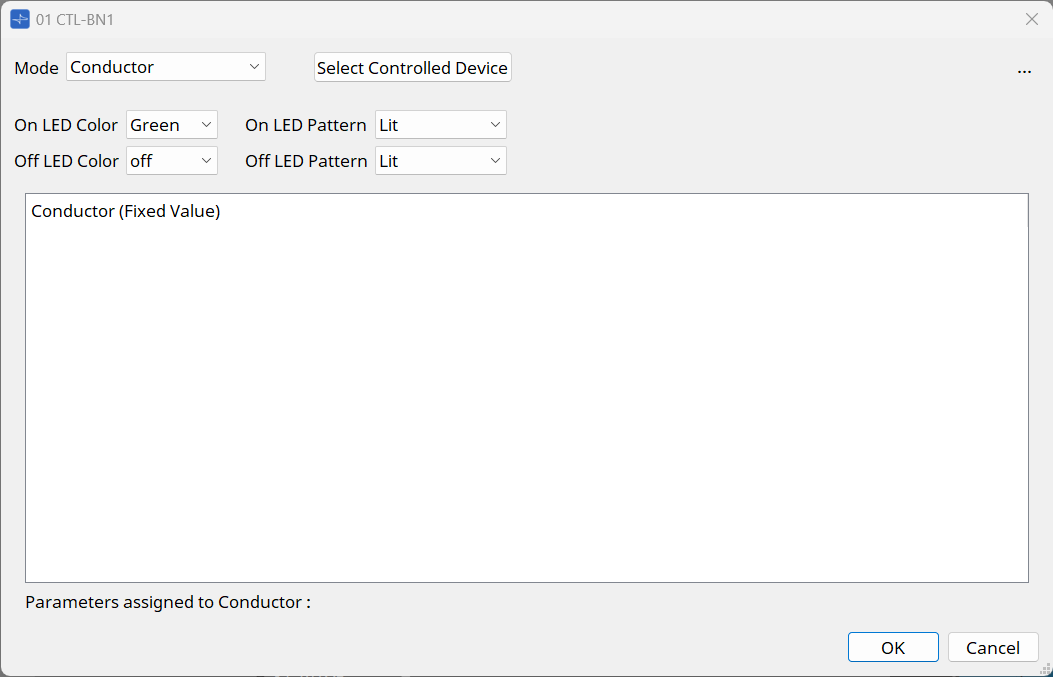
The editor will appear when you double-click the CTL-BN1 placed on the "Project" sheet.

① [Mode] list box
Select Conductor or External Event.
②LED Settings
-
On/Off Color
Sets the color of the LED when the button of the CTL-BN1 is on or off. -
On/Off Pattern Specifies the color of the LED when the button of the CTL-BN1 is on or off.
You can choose from the following three patterns.-
Lit: Lights up
-
Slow Flash: Slowly flashes
-
2Times Flash: Flashes twice
-
5. Mode
5.1. Conductor
The CTL-BN1 controls the Fixed Value component of the DME’s Conductor, allowing the DME to change parameters of peripheral devices, recall presets, etc. For details on the Conductor function, refer to "Conductor" in "ProVisionaire Design Component Guide."
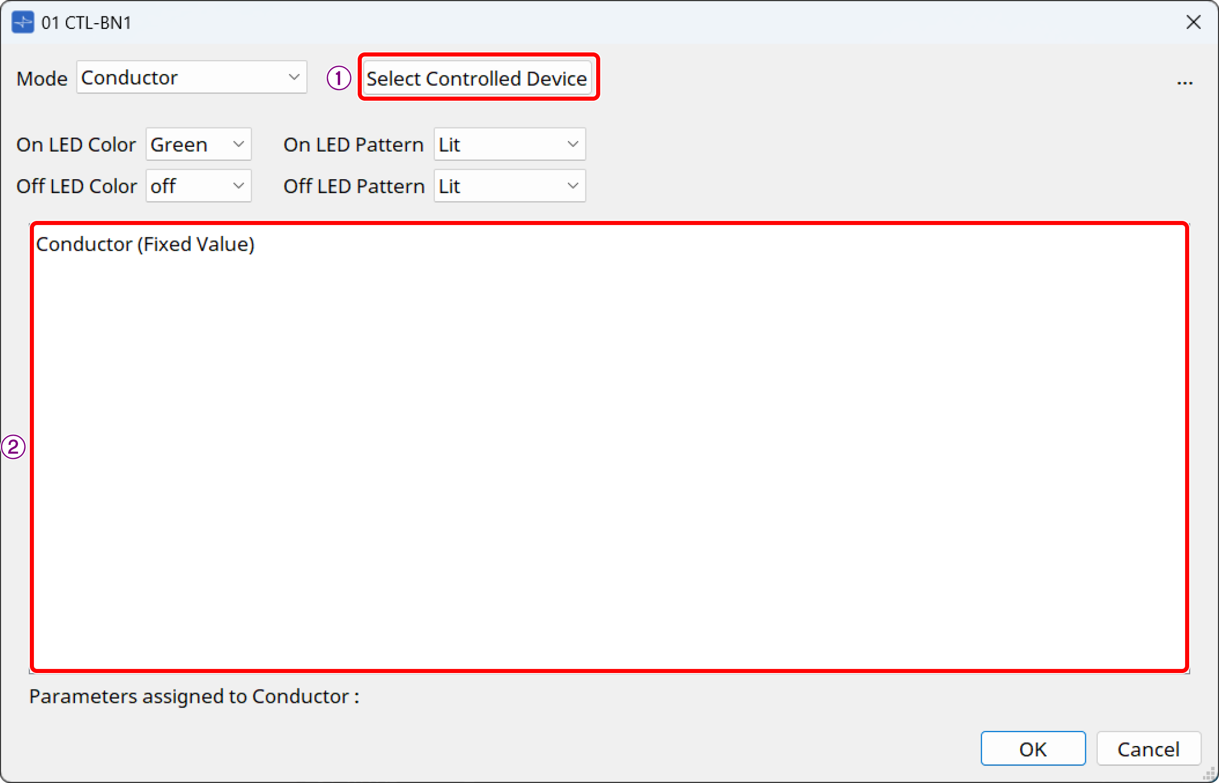
① [Select Controlled Devices] button
Sets the search method for DMEs that have Conductor components to be controlled by the CTL-BN1.
This button is enabled when Mode is set to "Conductor."
Click this button to display the dialog box.
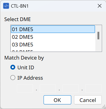
-
Select DME
Select the DME that will execute the Conductor function. -
Match Device by
Select the search method for DMEs between Unit ID or IP Address.
② List
The list numbers and labels of the DME’s Conductor components will be displayed (1 to 256).
| If you have not yet registered Conductor, first register the parameters and other items to be recalled in the Conductor component editor. For details, refer to "Conductor" in "ProVisionaire Design Component Guide." |
5.2. External Event
The CTL-BN1 sends TCP/UDP commands to control a desired device.
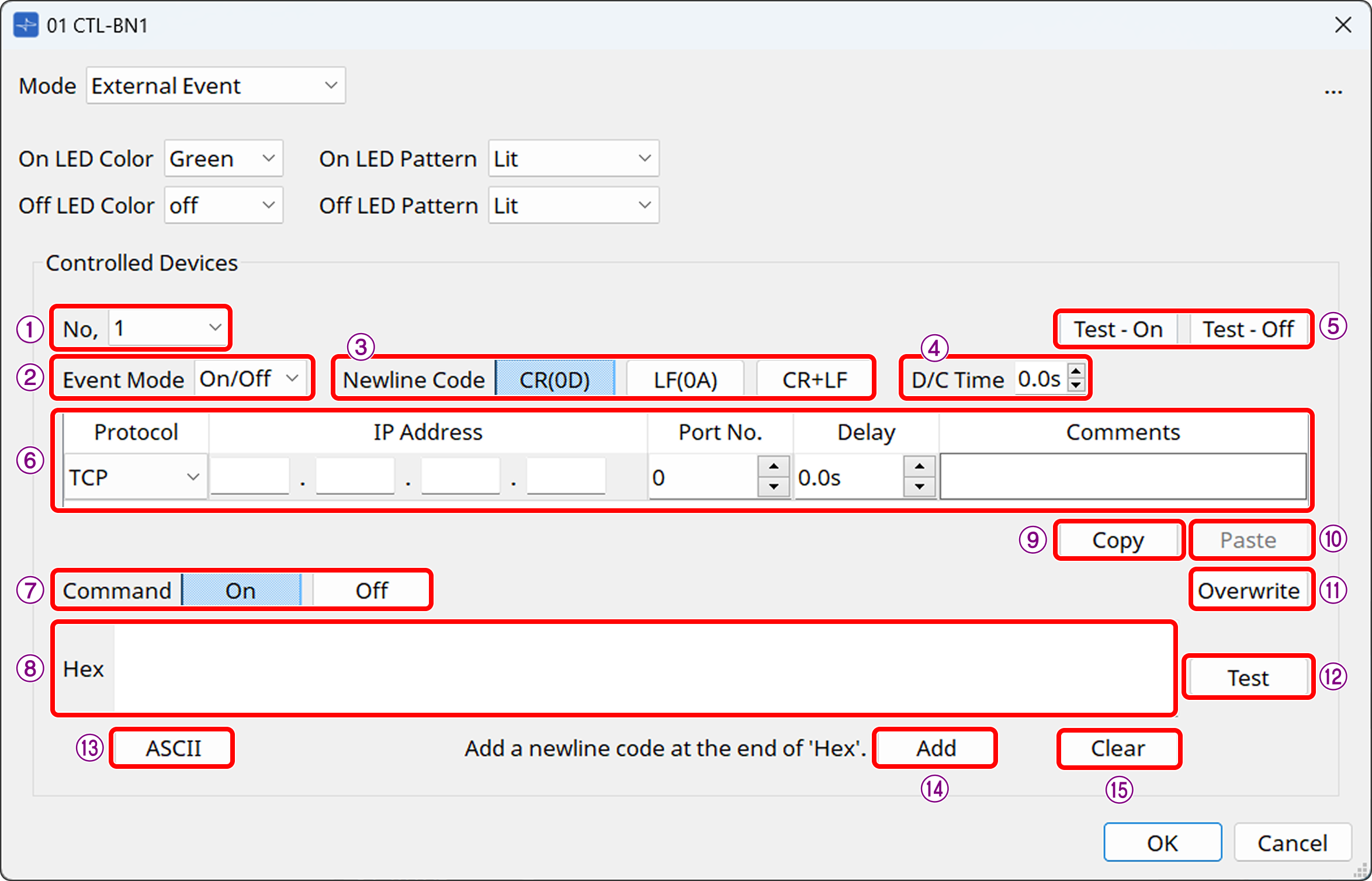
① [No.] list box
Select the command to edit. Up to five commands can be set.
② [Event Mode] list box
On/Off: On and Off commands are sent alternately each time the function is executed.
1shot: A command is issued when the button is pressed.
③ [Newline Code] button
Select the line break code to be entered when a line break is entered in the [Hex] field or at the end of a command using the [Add] button. You can choose from CR(0D), LF(0A), and CR+LF.
④ [D/C Time] (TCP only)
Specifies the time until communication with the device is disconnected after a command is sent. If the device cannot be controlled properly, adjust the disconnection time.
⑤ [Test-ON] and [Test-Off] buttons
ProVisionaire Design will issue events 1 to 5 as configured.
⑥ Event area
-
Protocol: Select the protocol type between UDP and TCP.
-
IP Address: Specifies the send destination for the command.
-
Port No.: Specifies the send destination for the command. You can specify a value between 0 and 65535.
-
Delay: Specifies the time from the time the Function is executed until each command is issued. The maximum time is 60 seconds.
-
Comments: You can write a free comment as a note.
⑦ [Command] button
If "On/Off" is selected in Event Mode, set commands respectively for On and Off.
⑧ [Hex] field
Enter a hexadecimal command. The maximum size is 256 bytes.
⑨ [Copy] button
Copies the command settings.
⑩ [Paste] button
Pastes the copied command settings to commands for another No.
⑪ [Overwrite] button
When this button is turned on, the command entry in the [Hex] field will be the overwrite method at the cursor position. When it is turned off, the insert method will be enabled.
⑫ [Test] button
Sends a command to the device specified by ProVisionaire Design to confirm the command.
Use this button if the CTL-BN1 is not available.
⑬ ASCII button
Enter a string in the text box in the dialog box that appears when you click this button, and then press Covert. The string will be converted to hexadecimal and displayed in the Hex field.
If Hex is entered before the dialog box opens, the hexadecimal number will be converted to a string and displayed.
When you press the Convert button, the line break code selected in New Line Code will be used.
| Even if 0D is embedded in the Hex when you open the dialog box, if LF is selected in New Line Code, 0D will be converted to 0A when you press Convert. |
⑭ [Add] button
Click this button to insert the line break code selected in [Newline Code] at the end of the command.
⑮ [Clear] button
Click this button to clear [Hex].