

OSCILLATOR popup window
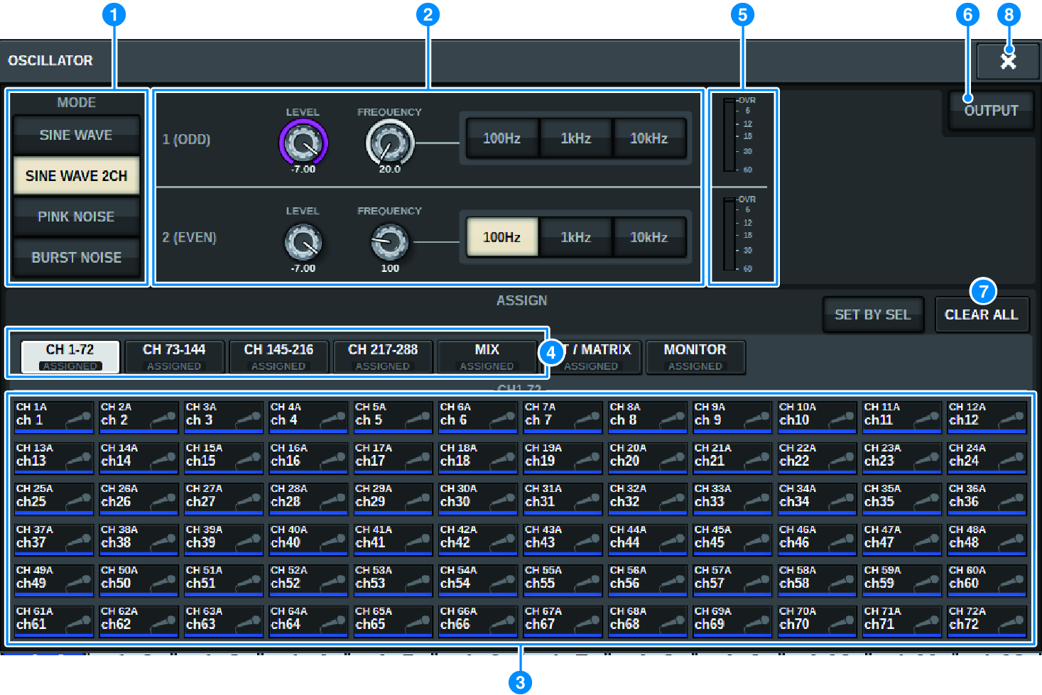
This screen contains the following items.
a | OSCILLATOR MODE buttons Select one of the following four oscillator operating modes: |
SINE WAVE A sine wave is output continuously.
SINE WAVE 2CH Two sine waves (with different frequencies) are output separately.
PINK NOISE Pink noise is output.
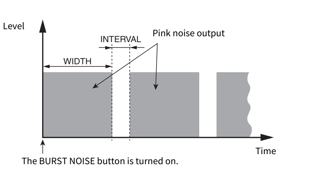
BURST NOISE Pink noise is output intermittently.
b | Parameter field Enables you to set the oscillator parameters. The controllers and their functions in this field vary depending on the operating mode a. |
SINE WAVE:
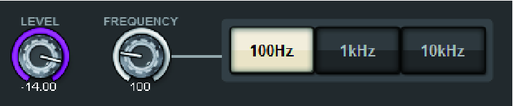
- LEVEL knob
- Indicates the output level of the sine wave. Use the screen encoder to adjust the value.
- FREQUENCY knob
- Indicates the frequency of the sine wave. Use the screen encoder to adjust the value.
- FREQUENCY buttons
- Enables you to select the sine-wave frequency from 100 Hz, 1 kHz, and 10 kHz.
SINE WAVE 2CH:
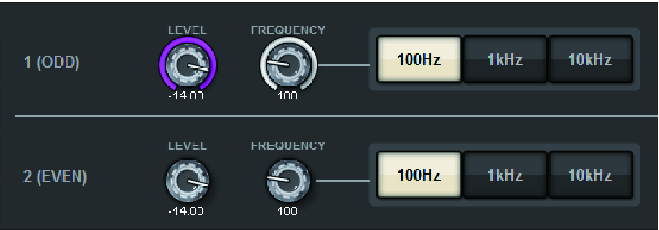
- LEVEL knob (ODD)
- Indicates the output level of the odd-channel sine wave. Use the screen encoder to adjust the value.
- FREQ knob (ODD)
- Indicates the frequency of the odd-channel sine wave. Use the screen encoder to adjust the value.
- LEVEL knob (EVEN)
- Indicates the output level of the even-channel sine wave. Use the screen encoder to adjust the value.
- FREQ knob (EVEN)
- Indicates the frequency of the even-channel sine wave. Use the screen encoder to adjust the value.
- FREQUENCY buttons
- Enables you to select the sine-wave frequency from 100 Hz, 1 kHz, and 10 kHz.
The default frequency is 1 kHz for the odd channel and 400 Hz for the even channel. Two meters (odd and even) will be displayed.
PINK NOISE:

- LEVEL knob
- Indicates the output level of the pink noise. Use the screen encoder to adjust the value.
- HPF knob
- Indicates the cutoff frequency of the HPF that processes the pink noise. Use the screen encoder to adjust the value. Use the button below the knob to switch the HPF on or off.
- LPF knob
- Indicates the cutoff frequency of the LPF that processes the pink noise. Use the screen encoder to adjust the value. Use the button below the knob to switch the LPF on or off.
For BURST NOISE:
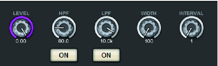
- LEVEL knob, HPF knob, LPF knob
- These are the same as for the PINK NOISE mode.
- WIDTH knob
- Indicates the length of noise being output intermittently. Use the screen encoder to adjust the value.
- INTERVAL knob
- Indicates the length of silence between noise bursts. Use the screen encoder to adjust the value.
c | ASSIGN section Enables you to select a channel to which the oscillator signal will be sent. Press one of the five tabs below to select the type of channels/buses displayed, and then press the button(s) for the desired channels/buses (multiple selections are allowed). If SINE WAVE 2CH mode is selected, output signals will vary depending on whether the selected channel number is odd or even. For example, the odd-channel signal will be routed to MIX1 and the even-channel signal will be routed to MIX2. You can press the CLEAR ALL button to defeat all selections. |
d | Channel display select buttons Select the type of channels that you want to view on screen. Available options are CH1-72, CH73-144, MIX, ST/MTRX, and MONITOR. (The number of channels varies depending on the connected DSP engine.) A green “ASSIGNED” indicator lights up on buttons that contain a channel/bus selection. |
e | Meter section Indicates the oscillator output level. |
f | OSCILLATOR OUTPUT button Turns the oscillator on or off. If this button is turned on, the oscillator signal will be sent to the input channel or bus you selected in the ASSIGN section. When you press the button again, the oscillator will turn off. |
g | CLEAR ALL button Excludes all output channels from the oscillator signal destination. |
h | CLOSE button Closes the OSCILLATOR popup window. |