

Viewing a touch screen
The touch screens display the following information:
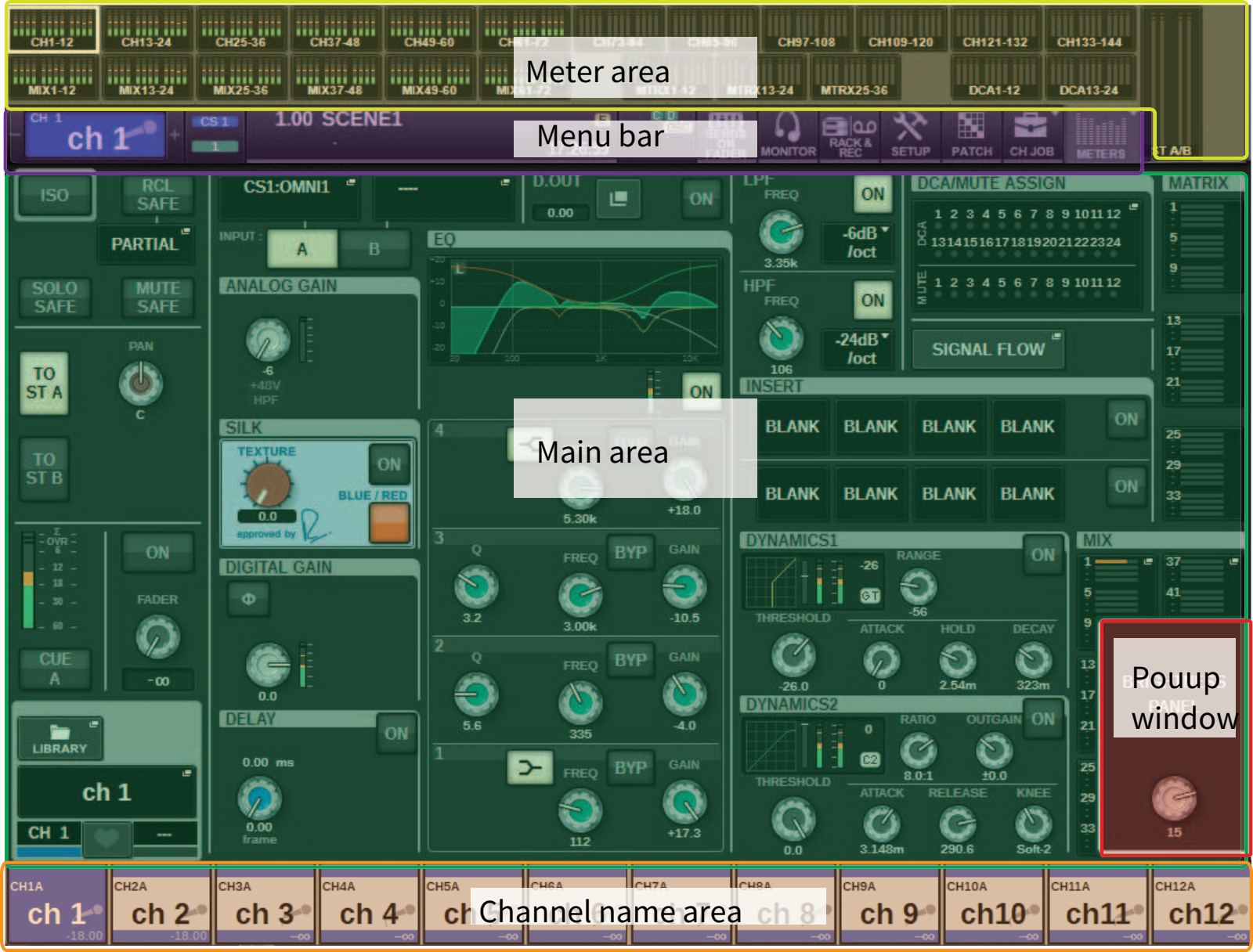
Meter area
The meter area displays various meters. Press any part of the meter area to recall the corresponding fader layer to the panel.
Main area
The contents of the main area will vary depending on the currently-selected function. Mixing operations will involve mainly the following two types of screens. To access these screens, press the [VIEW] key.
SELECTED CHANNEL VIEW screen
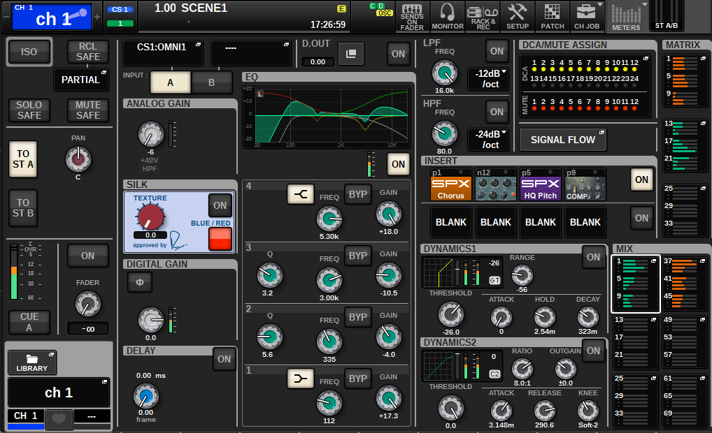
This screen shows all mix parameters of the currently-selected channel. For details about this screen, refer to the “About the SELECTED CHANNEL VIEW screen” section.
OVERVIEW screen
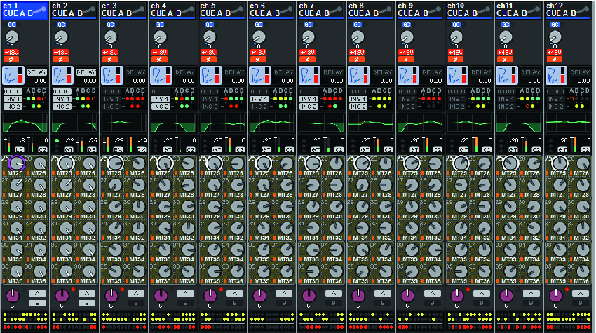
This screen shows the main parameters of 12 channels selected as a layer. For details about this screen, refer to the “About the OVERVIEW screen” section.
Menu bar

a | Selected channel This area shows the number, name, icon, and channel color of the channel that is currently selected for operation. For details on assigning a name, refer to “Entering names.” For details on selecting an icon, refer to ““Changing the name”.” Press the left side of the selected channel area to select the preceding channel. Press the right side of the area to select the next channel. |
b | Connection This indicates the ID of the control surface and the unit ID of the DSP engine that is connected. Here you can also check whether the DSP engine is operating in active mode or in standby mode. Not shown: DSP not found Green: found as active Gray: found as standby (switchable) Gray slanting line: found as standby (not switchable) Grayed out: DSP assumed to be in standby is not found. When DSP mirroring is used, this also operates as a button to access the System Config screen. |
c | INFORMATION This area displays information such as the current time and a scene number. If you press this area, the SCENE LIST window will appear in the main area, allowing you to set scenes. In Preview mode, this flashes red. |
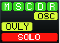
d | Status indicator This area indicates the current status. The following table shows the displayed content and the corresponding status. |
Indicator | Conditions |
|---|---|
M | Status of the TWINLANe network (MAIN) Green: Online (Normal) Yellow: Online (Not in the ring connection) Red: Wiring problem Blue: Out of sync Gray: Offline |
S | Status of the TWINLANe network (Sub) Green: Online (Normal) Yellow: Online (Not in the ring connection) Red: Wiring problem Blue: Out of sync Gray: Offline |
C | Status of the Console network Green: Online (Normal) Yellow: Online (Not in the ring connection) Red: Wiring problem Blue: Out of sync Gray: Offline |
D | Status of the DSP engine Green: Normal Yellow: Only POWER A or B is enabled. Red: Error (inoperative fan, etc.) |
R | Status of the I/O rack Green: Normal Yellow: Only POWER A or B is enabled. Red: Error (inoperative fan, etc.) |
OSC (yellow) | Oscillator is enabled. |
ALT (yellow) | Alternate function ON |
TB (yellow) | Talkback is enabled. |
REC (red) | Currently recording an audio file |
PLAY (green) | Currently playing an audio file |
OVLY (yellow) | Overlay ON |
VSC (yellow) | Virtual sound check ON |
LINK (yellow) | Temporary link ON |
CUE A, CUE B, CUE A+B, CUE S, CUE A+S, CUE B+S, CUE A+B+S (yellow) | Status of cue |
Solo mode ON | SOLO (red) |
ACCESS | Communicating with the USB flash drive |
- The ACCESS indicator will appear while data is being accessed (i.e., saved, loaded, or deleted). Do not disconnect the USB flash drive or power-off the unit while this indicator is shown. Doing so may damage the flash drive, or may damage the data in the unit or on your media device.
e | SENDS ON FADER Press this button to switch to SENDS ON FADER mode, in which you can use the faders of the top panel to adjust the MIX/MATRIX send level (see “Using the faders to adjust the sends (SENDS ON FADER mode)”). During this time, the main area will switch to a screen that enables you to select the send-destination MIX/MATRIX bus. |
f | MONITOR When you press this button, the MONITOR screen will appear in the main area, enabling you to edit the monitor or oscillator settings. |
g | RACK & REC (Recorder) When you press this button, the RACK & REC screen will appear, enabling you to configure plug-ins. You can also make settings for the recorder function (USB), which allows you to record and play back audio files. |
h | SETUP When you press this button, the SETUP screen will appear in the main area, enabling you to make basic and user-specific settings for the RIVAGE PM series. |
i | PATCH When you press this button, the PATCH screen will appear, enabling you to configure in/out, direct out, recording, and other patches. |
j | CH JOB (Channel Job) Press this button to access the CH JOB pull-down menu, in which you can copy or initialize the channel settings, etc. |
k | METER When you press this button, a popup menu will appear, enabling you to select the type of channel block to display in the meter area (Meter). |
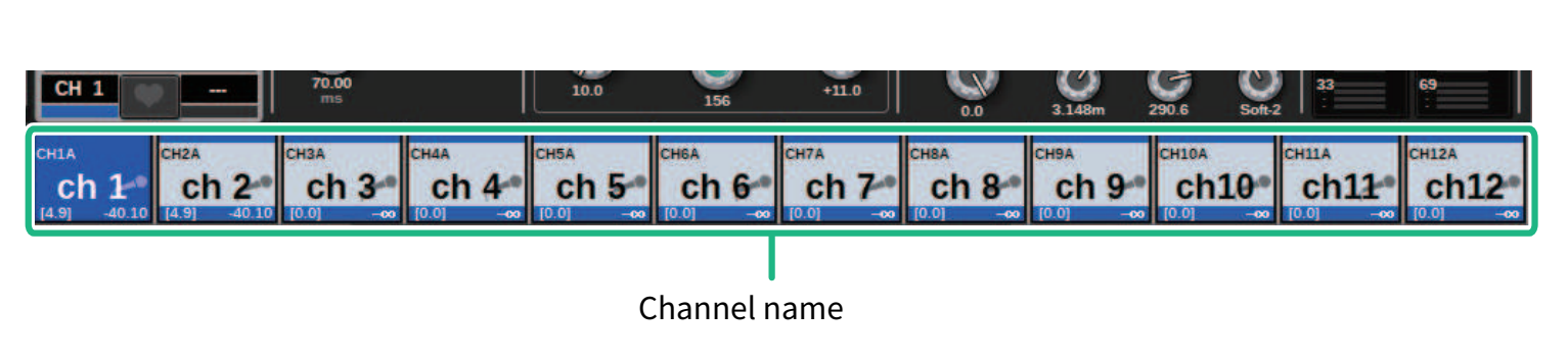
Channel name area
Press the channel name area to switch the selected channel/parameter on the screen. If you switch fader layers, the indication in this area will reflect the change in layer selection. In this way, you can access any channel on screen.
- Switching layers will not affect the selected channel/parameter on the screen. The 12-channel group displayed on the OVERVIEW screen will change. However, unless you press the channel name area, the selected channel/parameter on the screen will remain unchanged since your last press of the [SEL] key(s). If you want to switch the selected channel/parameter on screen at the same time you switch layers, you can configure this arrangement by selecting [FADER BANK] > [SEL] LINK in the Preferences settings.
When you use a screen encoder to control an EQ or dynamics parameter in the SELECTED CHANNEL VIEW screen, the corresponding parameter and its value will appear in the upper part of the channel name area.
EQ

Dynamics

MIX/MATRIX SENDS

The following functions will be displayed.
* If ALTERNATE FUNCTION is assigned to a USER DEFINED key, pressing the channel screen encoder repeatedly will turn the function on and off.
For the SENDS function, rotate the screen encoder to set PRE or POST.
You can also turn the function on or off by pressing the screen encoder while holding down the [SHIFT] key.