DYNAMICS Screen

This allows for all dynamics parameters to be displayed and edited. This is convenient when you want to make detailed dynamics settings for a specific channel.
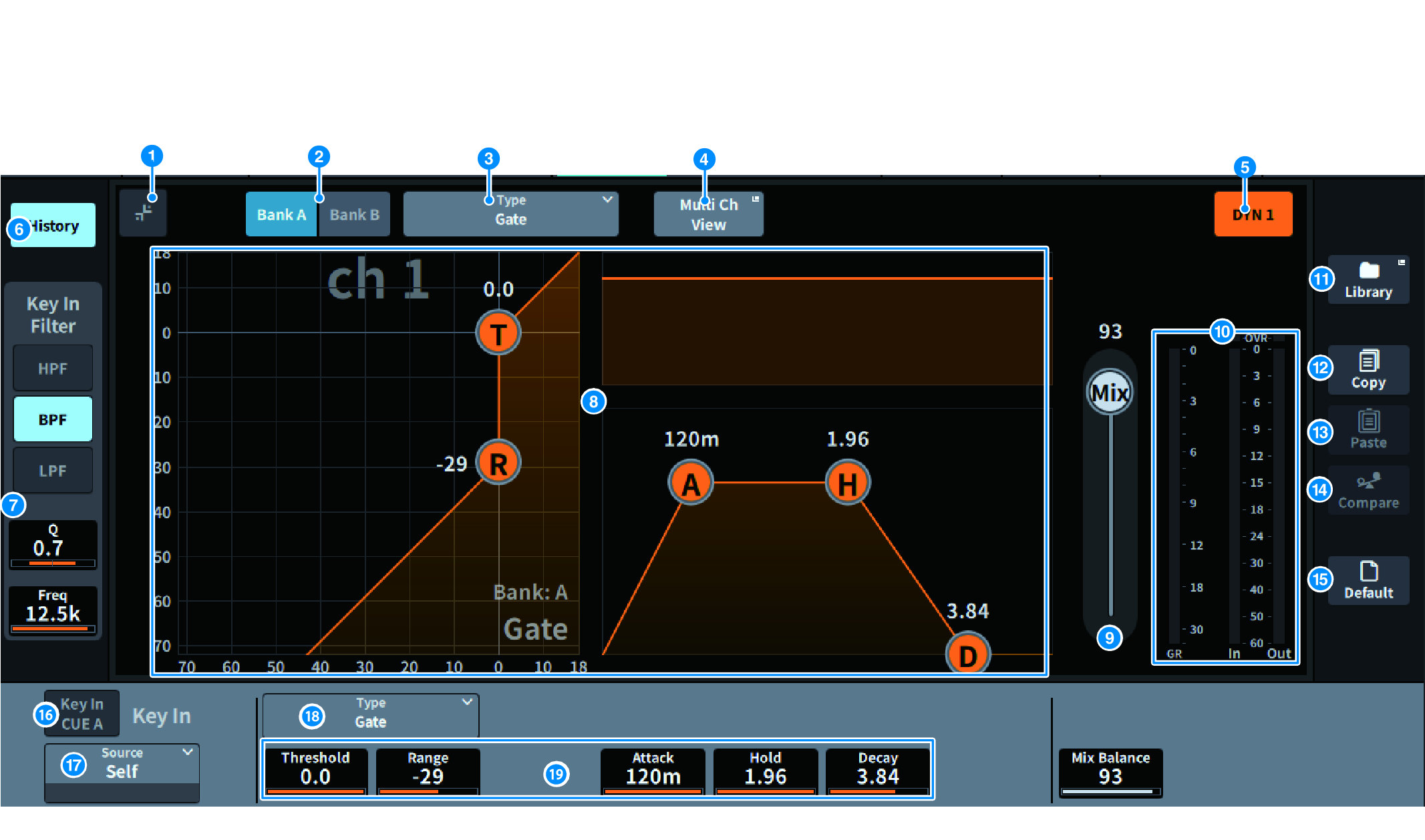
a

Expand/collapse button

Expands or collapses the screen.

b

Bank button

This allows you to switch between A and B as the store destination for the dynamics parameters.

c

Type button

Switches dynamics type between LEGACY COMP, COMP260, GATE, DE-ESSER, EXPANDER, DUCKING, FET Limiter (input channel DYN2 and output channel DYN1 only), and Diode Bridge Comp (input channel DYN2 and output channel DYN1 only).

d

Multi Ch View button

Opens the Multi Ch View screen.

e

Dynamics ON/OFF button

Switches dynamics on/off.

f

History button

When this is pressed, the last 10 seconds of history of the dynamics graph is displayed.

g

Key In Filter field (This area is not displayed if the dynamics type is De-Esser, FET Limiter, or Diode Bridge Comp.)

This function sets the filter settings for the key-in signal pass.

  • Filter selection button
  • Select the type of filter from HPF, BPF, or LPF. Press a button that is on to disable the filter.
  • Q
  • Displays the filter Q setting. When the screen is pressed to select, the value can be changed by sliding vertically or horizontally or using the [TOUCH AND TURN] knob.
  • FREQUENCY
  • Display the cutoff frequency setting of the filter. When the screen is pressed to select, the value can be changed by sliding vertically or horizontally or using the [TOUCH AND TURN] knob.

h

Dynamics graph

Displays the input/output characteristics of the dynamics processors.

i

Mix Balance

The balance with the input signal can be adjusted.

j

Dynamics IN/OUT level meters, GR meter

These meters display the peak level of the signals before and after the dynamics processing, and the amount of gain reduction. For a stereo channel, these meters display the level of both the L and R channels.

k

LIBRARY button

Press this to display the CH LIBRARY screen.

l

COPY button

Copies the dynamics parameter settings stored in the bank (selected via the A/B switching buttons) to buffer memory.

m

PASTE button

Press this button to paste the settings that were copied in buffer memory to the dynamics of the currently-selected bank. If valid data has not been copied into buffer memory, pasting is not possible.

n

COMPARE button

Press this to switch between and compare the settings stored in buffer memory and the currently-selected settings. If valid data is not stored in the buffer memory, comparison is not possible.

o

DEFAULT button

Press this button to reset all dynamics parameters to the initial values.

p

KEY IN CUE button

This button cue-monitors the signal that is selected as the KEY IN SOURCE. The CUE will be canceled when you move to a different screen.

NOTE

  • Even if the Cue mode is set to MIX CUE (the mode in which all channels whose [CUE] key is on are mixed and monitored), turning on the KEY IN CUE button will cause only the signal of the corresponding channel to be monitored. All [CUE] keys that had been turned on at that time will be forcibly canceled.

q

KEY IN SOURCE selection button

Allows you to select one of the following as the key-in signal that will trigger dynamics processing.

  • Self ..............Signal from the same channel.
  • Other Pre DYN1 ...........Pre-DYN1 signals on other channels (selected from a group of 24 channels each) (only Input Ch DYN1)
  • Other Pre Proc ..........Pre-Proc signals on other channels (selected from a group of 24 channels each) (only Input Ch DYN2)
  • MX Out ...........MIX channel output signal
  • EXT IN 1-4 ...........Signal selected as EXT IN 1-4

r

Type button

Select the type of dynamics from the following.

  • Legacy Comp .............. This is a standard compressor that has been equipped with many of Yamaha’s legacy digital mixers, such as PM1D and PM5D.
  • Comp 260 ...........This is an analog-flavored compressor built using Yamaha’s proprietary VCM (Virtual Circuitry Modeling) technology. The compression curve setting (Knee) can be selected from 6 levels: Hard / Soft-1 / Soft-2 / Soft-3 / Soft-4 / Soft-5. Although the attack/release times can also be adjusted, the preset settings reproduce the fixed characteristics of the original unit being modeled.
  • Gate ..........This dynamics type reduces the output by a fixed value (Range) when a signal smaller than the Threshold level is input.
  • De-Esser ...........This dynamics type detects only the sibilants and other high-frequency consonants of the vocal, and compresses its bandwidth.
  • Expander ........... This dynamics type reduces the output by a fixed ratio when a signal smaller than the Threshold level is input.
  • Ducking ........... This dynamics type reduces the output by a fixed value (Range) when a signal greater than the Threshold level is input. This is effective if you want to lower the volume level of background music using the Key In Source signal.
  • FET Limiter ........... This is a model of a FET compressor/limiter commonly used in studios. Because THRESHOLD is fixed internally, the degree of compression is adjusted by adjusting the INPUT level. (Input channel DYN2 and output channel DYN1 only)
  • Diode Bridge Comp ........... This is compressor modeling using Diode Bridge.(Input channel DYN2 and output channel DYN1 only)

s

Dynamics parameter settings

Displays the dynamics parameter values. These can be adjusted using the screen encoder. The type of parameters will vary depending on the currently-selected dynamics processor type.