Making connections
3. Making connections
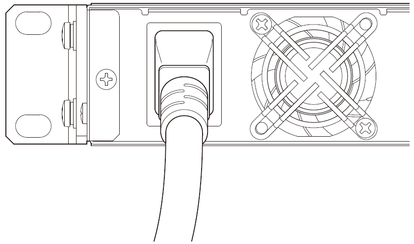
3.1. Power On/Off
-
To turn the power on, first connect the power cord to the unit and then plug it into an AC outlet.
-
To turn the power off, unplug the power cord from the AC outlet.
| The DME5/DME3 does not feature a power button. Turn the power on/off by plugging and unplugging the power cord. |
![]() Caution
Caution
-
When turning the power on, wait at least 5 seconds after turning the power off. Otherwise, a malfunction may occur.
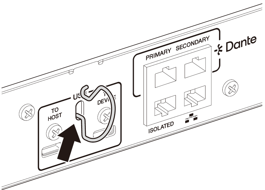
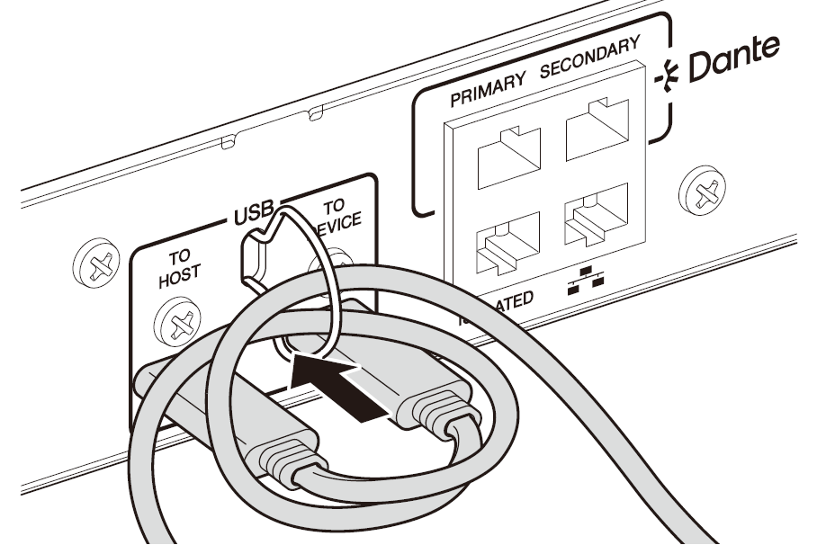
3.2. Installing the Cable Hook
To prevent the USB cable from being accidentally disconnected, follow the steps below to install the included cable hook.
-
Hook one end of the included cable hook onto the lower end of the security slot, located between the USB connectors on the rear panel.
-
Insert the other end of the hook into the upper end of the security slot.
-
Insert the USB cable through the hook, and then connect it to one of the USB connector.
3.3. Installing Euroblock connectors
Use the included Euroblock connectors to connect to the [INPUT], [OUTPUT], or [GPI] connectors.
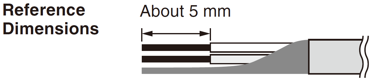
3.3.1. Preparation and processing cable wires
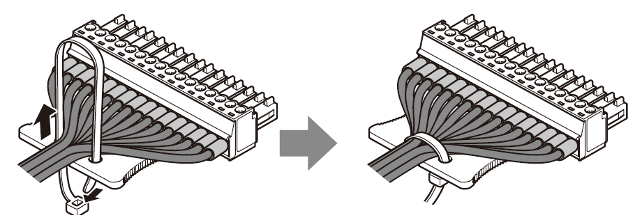
Strip the cable to be connected to the Euroblock connector as shown below and connect the lead wires. Note that the weight or vibration of wires connected to the Euroblock can cause lead wire breakage due to metal fatigue. Secure the cable to the tab on the Euroblock connector using the included cable tie.
![]() Caution
Caution
-
If the Euroblock is connected using lead wires, do not plate the wires with solder.
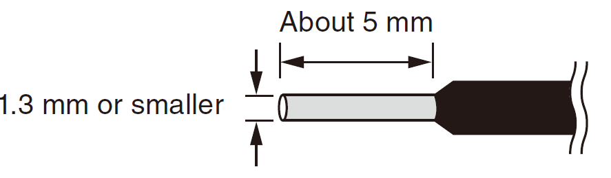
If wires are frequently disconnected and reconnected, the use of pin terminals with an insulation sleeve is recommended. Use pin connectors like the one shown below.
Use a model with a diameter up to 1.3 mm and length of about 5 mm (such as the Phoenix Contact model AI0, 5-6WH).
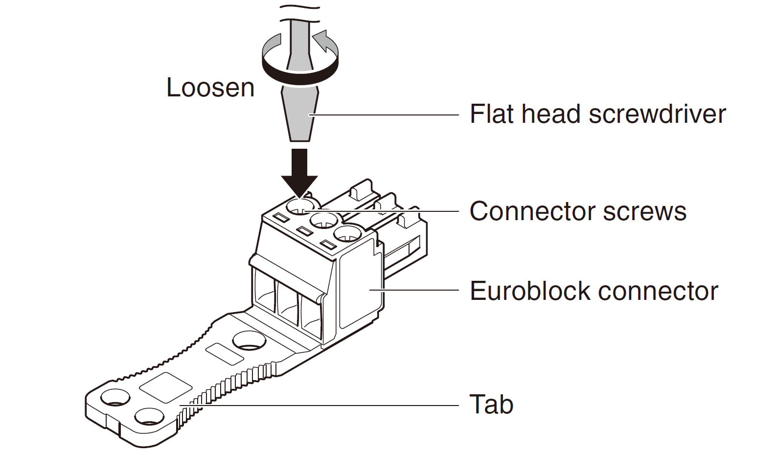
3.3.2. Attaching a Euroblock connector
In this section, a 3-pin Euroblock connector for the [INPUT]/[OUTPUT] connectors is used as an example to explain how to attach a Euroblock connector.
-
Loosen the connector screws.
 NOTE
NOTE
-
Use a flat-head screwdriver with a blade width of 2 mm or less for the Euroblock plugs (16-pin) for the [GPI] connectors, and 3 mm or less for the Euroblock plugs (3-pin) for the [INPUT]/[OUTPUT] connectors.
-
-
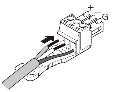
Insert the cable.
-
Tighten the connector screws securely.
Pull the cable to make sure that it cannot be pulled out accidentally. -
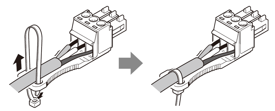
Use the included cable tie to secure the cable to the tab.
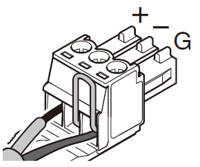
For [INPUT]/[OUTPUT] connectors (3-pin)
For [GPI] connectors (16-pin)
 NOTE
NOTE
-
Trim off any unnecessary sections of the cable tie.
-
-
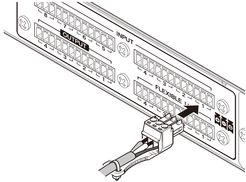
Attach the Euroblock connector to the [GPI] connector or [INPUT] or [OUTPUT] connector on the unit.
![]() NOTE
NOTE
-
If connecting an unbalanced cable to the [INPUT] connector, connect the “−” and “G” of the Euroblock with a jumper wire.
3.4. Connecting to a [GPI] connector
Connect GPI (General Purpose Interface) devices to the [GPI] connectors on the rear panel. GPI is used to input and output control signals to and from external devices such as controllers.
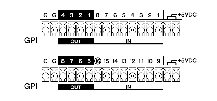
Each [GPI] connector of the DME5 has 16 input connectors and 8 output connectors.
Each [GPI] connector of the DME3 has 8 input connectors and 4 output connectors.
-
The output voltage of each +5VDC terminal is 5 V. The maximum current that can be drawn from the two +5VDC terminals is 100 mA in total.
When using a switch/variable resistor and an LED/relay at the same time, connect the switch/variable resistor to one terminal and the LED/relay to the other terminal. -
The DME5’s [IN] terminals 1 to 15 and the DME3’s [IN] terminals 1 to 7 detect voltages between 0 and 5 V.
Only the DME5 [IN] terminal 16 and the DME3 [IN] terminal 8 support +24 V input, detecting voltages between 2.5 and 24 V as High and voltages below 2.5 V as Low. -
[OUT] terminals are open collector outputs that switch between open or ground. The maximum voltage that can be applied is +12 V. The maximum current that can be applied is 75 mA per port.
Use ProVisionaire Design to assign parameters to GPI controllers and make other settings.
![]() NOTE
NOTE
-
Specifying input/output channels in ProVisionaire Design allows presets from a connected GPI external device to be recalled, parameters to be changed, and signals to be sent to GPI external devices. For the setup method, refer to the "ProVisionaire Design User Guide".