Configuring the device
With Yamaha LAN Monitor, you can configure some of the functions for Yamaha switches and Yamaha wireless LAN access points.
There are the following three methods for setting the device.
| Setting method | Descriptions |
|---|---|
You can set basic items such as IP address and device name. |
|
Using the device’s Web GUI, detailed settings for each function can be made. |
|
By importing a backup or pre-prepared CONFIG, you can apply the settings for each function all at once. |
1. “Device Settings” dialog
The “Device Settings” dialog can be displayed in the following two ways.
Either way, the same dialog will be displayed.
-
Map screen - “Device Details” view - “Device Settings” button
-
List screen - “L2MS Agent List” tab - “Setting” button
The setting items displayed in the dialog vary from model to model.
1.1. For non-SWX2110/SWX2110P series Yamaha switch and Yamaha wireless LAN access point
Basic items such as label settings, device name settings, and IP address settings can be configured.
Only items that are supported by the device will be displayed.
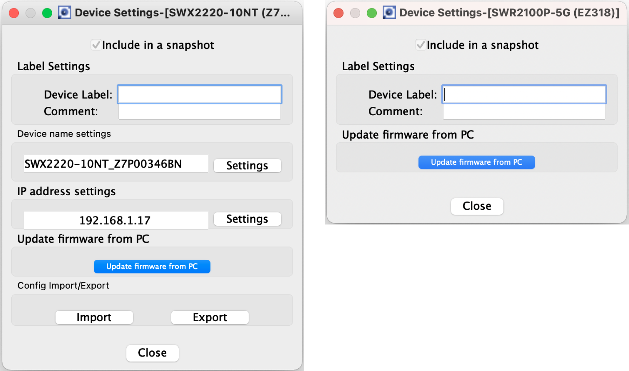
[Include in a snapshot] check box |
Turns the snapshot function on/off for each device. For an agent device, this is fixed on. |
|---|---|
“Label Settings” |
You can enter any label or comments you like to identify each device. |
“Device name settings” |
Click the [Set] button to display the “Device name settings” dialog. |
“IP address settings” |
Click the [Settings] button to display the “IP address settings” dialog box. |
[Update firmware from PC] button |
Click the [Update firmware from PC] button to display the “Update firmware from PC” dialog box. |
“Config Import/Export” |
Click the [Import] button to display the “CONFIG import” dialog. |
[Close] button |
When you click this, the “Device Settings” dialog box closes. |
|
Some items will not be displayed until the firmware revision is acquired. If some items are not displayed, please wait for a while and then open the Device Settings dialog again. |
1.2. For the SWX2110/SWX2110P series Yamaha switch
Use this to view or change the settings.
The tabs shown at the top of the dialog allow you to switch between information displays.
-
[Switch settings] tab: View or configure the settings of the Yamaha switch.
-
[Port settings] tab: Configure basic functions, VLAN, and other settings for each port.

- Switch settings
-
Device name
Changes the device name.
Click the [Settings] button to display the “Device name” dialog box.Label
Allows you to enter a label that distinguishes the individual device.
Click the [Settings] button to display the “Label” dialog box.Comment
Allows you to enter a comment.
Click the [Settings] button to display the “Comment” dialog box.Snapshot
Cannot be changed. This is fixed to “On.”
LED mode
Configures the LED mode settings.
Click the [Settings] button to display the “LED mode” dialog box.EEE
Configures the EEE settings.
Click the [Settings] button to display the “EEE” dialog box.Flow control
Configures the flow control settings.
Click the [Settings] button to display the “Flow control” dialog box.Loop detection
Configures the action of the switch when a loop is detected.
Click the [Settings] button to display the “Loop detection” dialog box.Port mirroring
Configures the port mirroring settings of the switch.
Click the [Settings] button to display the “Port mirroring” dialog box.QoS
Configures the QoS settings.
Click the [Settings] button to display the “QoS” dialog box.IGMP Snooping
Configures the IGMP snooping settings.
Click the [Settings] button to display the “IGMP Snooping” dialog box.Frame counter reset
Resets the frame counter.
Click the [Execute] button to display a “Frame counter reset” confirmation message.Firmware Update
Updates the firmware of the switch.
Click the [Execute] button to display the “Firmware Update” dialog box.CONFIG export
Export the CONFIG of the switch.
Click the [Execute] button to display the “CONFIG export” dialog.CONFIG import
Import the CONFIG of the switch.
Click the [Execute] button to display the “CONFIG import” dialog.Restart
Restarts the switch.
Click the [Execute] button to display a “Restart” confirmation message.Initialize
Initializes the switch.
Click the [Execute] button to display an “Initialize” confirmation message. - Port settings
-
Click the [Port settings] tab, and then click a port number to display the following setting items.
Basic functions
Configures the basic functions of the port.
Click the [Settings] button to display the “Basic functions” dialog box.Tag VLAN
Configures the tag VLAN settings.
Click the arrow ( ) to display the [Settings] button.
Click the [Settings] button to display the “Tag VLAN” dialog box.PoE power supply
Configures the PoE power supply settings.
This is displayed only for the SWX2110P-8G.
Click the [Settings] button to display the “PoE power supply” dialog box.
2. Web GUI
If the Yamaha switch provide a web page for configuring settings, you can display this web page in your browser to configure basic settings and perform device management. This web page is referred to as a Web GUI.
For more information on recommended browsers for viewing the Web GUI, check the URL below.
http://www.rtpro.yamaha.co.jp/RT/FAQ/gui/browser_en.html
|
2.1. Logging in to the Web GUI
To use the Web GUI, proceed as follows.
-
Click the [Web GUI] button on the “Device Details” view.
A password entry dialog box will appear.
-
Enter your [User name] and [Password].
For the factory-set user name and password, refer to the user manual of each model. -
Click either the [OK] or [Login] button.
The Web GUI screen of the device currently selected in the tree appears in the default browser.If the Web GUI does not appear, it could be that the IP address or subnet settings of the Yamaha switch or Yamaha wireless LAN access point and the computer do not match. Check the IP address and subnet settings.
2.2. Web GUI help
Detailed explanations are provided for the settings in each screen of the Web GUI.
To access the help page, click the [Help] button on the Web GUI screen.