

Input channel mixing engine section
This section describes the mixing engine section for the input channels.
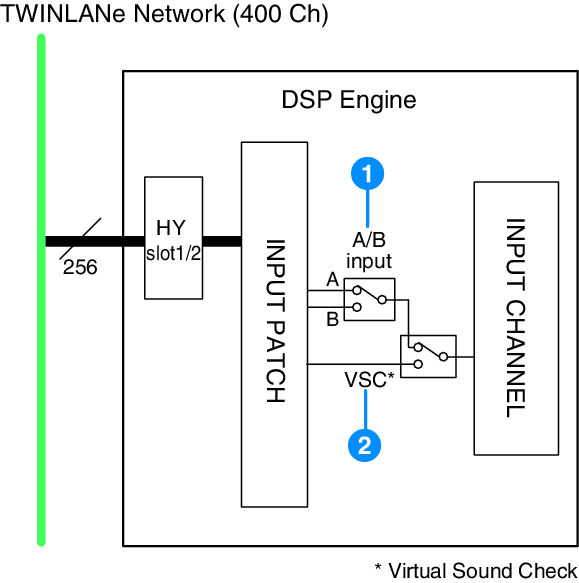
a | A/B input Switches between two sources A and B that are patched to the input channel. You can use this in the following ways.
|
b | Virtual Sound Check Switches all stage (I/O) inputs and DAW playback in a single operation. |
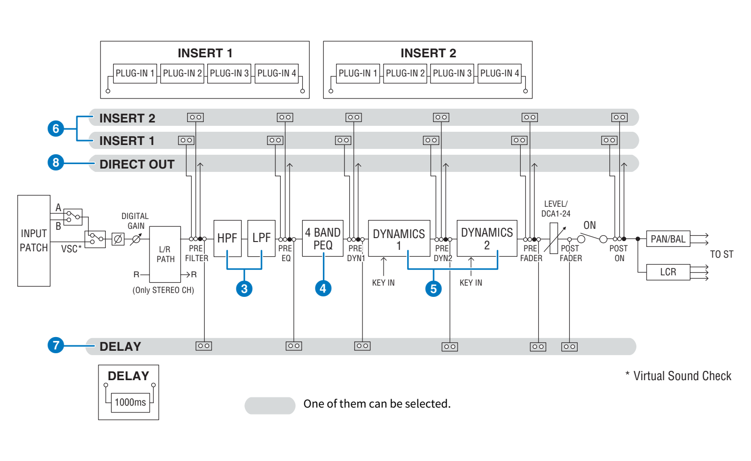
c | Filter
|
d | EQ This is a four-band parametric EQ.
|
The available EQ types include:
PRECISE | This EQ strives for ultimate precision and controllability. It enables you to adjust the target point precisely, and flexibly satisfies various requirements for sound making. Low/High Shelving filters feature a “Q” parameter, which enables you to adjust the knee characteristics. |
AGGRESSIVE | This EQ is musical and effective. It enables you to add a powerful, creative edge and serves as a powerful tool for artistic expression. |
SMOOTH | This EQ focuses on smooth sound qualities. It contributes to a natural sound without changing the atmosphere of the original. |
LEGACY | This is a standard EQ that has been equipped with many of Yamaha’s legacy digital mixers, such as PM1D and PM5D. |
e | DYNAMICS Two dynamics processor modules are provided: Dynamics 1 and Dynamics 2. To each module you can assign one of six types of function such as GATE or COMP. Two types of compressor are provided: LEGACY COMP and COMP 260. Two sets of dynamics parameter settings (A and B) can be saved for convenient comparison. The available dynamics types include: |
LEGACY COMP | This is a standard compressor that has been equipped with many of Yamaha’s legacy digital mixers, such as PM1D and PM5D. |
COMP 260 | This is an analog-flavored compressor built using Yamaha’s proprietory VCM (Virtual Circuitry Modeling) technology. It emulates the characteristics of compressors and limiters of the mid-1970s, which are now a standard for live sound reinforcement. This compressor has faithfully modeled the VCA (Voltage-Controlled Amplifier) circuit and the RMS (Root Mean Square) detection circuit. Compression curve (Knee) can be set to Hard, Medium, or Soft. Although the attack/release times can also be adjusted, the preset settings reproduce the fixed response of the original unit being modeled. Designed under the supervision of top SR engineers, the parameter effects have been optimized for live sound reinforcement. |
GATE | This dynamics type reduces the output by a fixed value (RANGE) when a signal smaller than the THRESHOLD level is input. |
DE-ESSER | This dynamics type detects only the sibilants and other high-frequency consonants of the vocal, and compresses its bandwidth. |
EXPANDER | This dynamics type reduces the output by a fixed ratio (RATIO) when a signal smaller than the THRESHOLD level is input. |
DUCKING | This dynamics type reduces the output by a fixed value (RANGE) when a signal greater than the THRESHOLD level is input. This is effective if you want to lower the volume level of background music using the KEY IN SOURCE signal. |
FET LIMITER *1 | Models a FET compressor/limiter used standard in studios. Because THRESHOLD is fixed internally, the amount of compression applied is adjusted by adjusting the INPUT level. |
DIODE BRIDGE COMP *1 | Models a compressor that uses a Diode Bridge. |
*1 Cannot be selected for input channel Dynamics 1.
・ KEY IN SOURCE
Selects the source of the key-in signal. In addition to SELF, the key-in signal can also be selected directly from another channel or input patch.
f | INSERT Two inserts are provided: Insert 1 and Insert 2. In each insert, you can insert up to four plug-ins/GEQ/PEQ/external devices (via the I/O jacks). Each insert point can be selected independently for INSERT 1 and INSERT 2. |
g | DELAY Up to 1000 msec of delay is provided on each channel. You can freely select the delay insert point. You can select the delay time unit from the following: meter, feet, sample, msec, frame, depending on your application. |
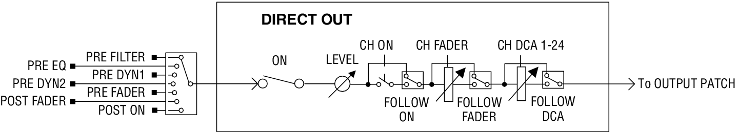
h | DIRECT OUT
|
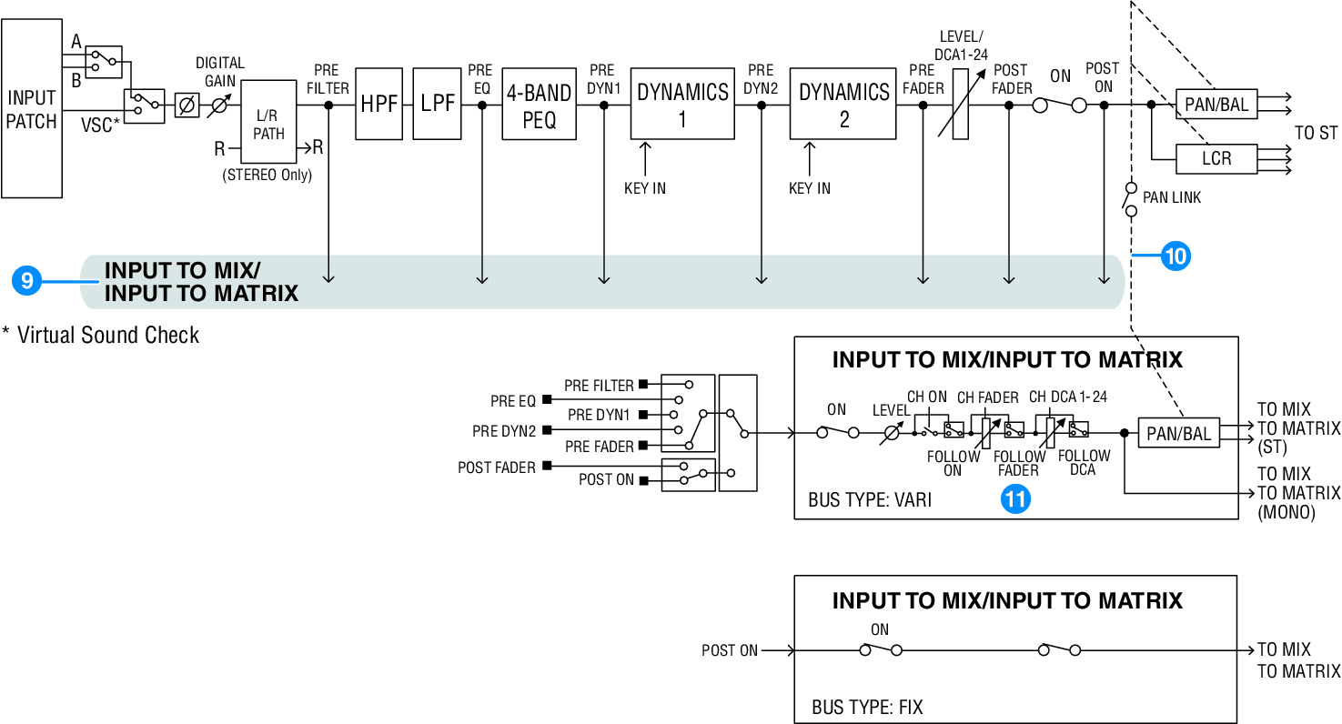
i | INPUT TO MIX/INPUT TO MATRIX A signal can be sent from the input channel to MIX buses 1 – 72. In addition to the conventional MIX sends, there are also direct sends to MATRIX buses 1 – 36, so by using these together you can use them as up to 108 mix buses.
|
PRE | POST |
|---|---|
PRE FILTER | POST FADER |
PRE EQ | POST ON |
PRE DYN1 | |
PRE DYN2 | |
PRE FADER |
j | PAN LINK With this setting, the signal sent from an input channel to the MIX/MATRIX bus can be made to follow the PAN of the STEREO bus send regardless of the send point. |
k | FOLLOW With this setting, the signal sent from an input channel to the MIX/MATRIX bus can be made to “follow” the channel FADER/ON/DCA settings regardless of the send point. For example, you can select whether or not a PRE FADER monitoring signal will follow the ON/OFF setting for the STEREO bus send. |
Pair setting
Adjacent channels can be paired and used as a stereo module. Either odd-numbered/even-numbered channels or even-numbered/odd-numbered channels can be specified as a combination. For single input channels (monaural), the pan level is nominal at the center, and +3 dB at hard left or hard right. If channels are paired, the level response of their balance will be nominal at center and +3 dB at far left or right.
Library
The “INPUT CHANNEL LIBRARY” lets you store and recall various input channel parameters.