Dynamics Plug-ins
Dynamics Plug-ins
Buss Comp 369
Buss Comp 369 emulates the bus compressor that has been used as the standard in recording studios and by broadcasters since the 1980s. In contrast to Compressor 276, which excels at creating aggressive compression sounds, it features smooth, natural compression that does not impair the expressiveness of the source.
It has both a built-in compressor and limiter, which can be used separately or in combination depending on the application. In addition, the rich harmonics of the input/output circuit audio transformer and discrete class A amplifier add depth and cohesiveness to the sound quality.
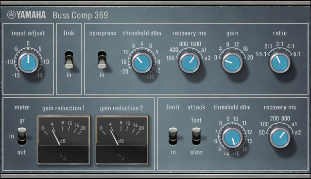
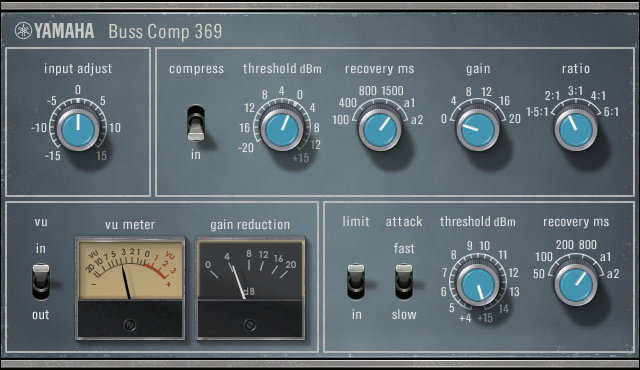
This plug-in operates in mono or stereo mode, depending on the channel configuration of the rack.
In stereo mode
In mono mode
- [INPUT ADJUST] Knob
-
Adjusts the input gain. However, the output gain changes in the opposite direction so that the passing volume (volume when [COMP IN] and [LIMIT IN] are off) does not change. For example, when [INPUT ADJUST] is +5 dB, the input gain is +5 dB and the output gain is -5 dB.
How INPUT ADJUST Works
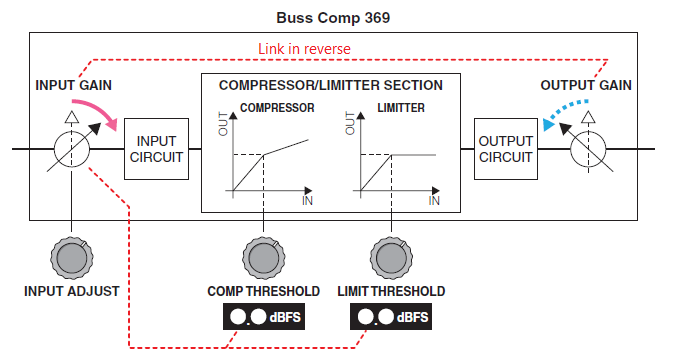
Since the threshold changes substantially, the displayed value changes in tandem. However, the internal state of the COMPRESSOR/LIMITER SECTION does not change.
- [LINK] Switch (in stereo mode)
-
Activates/Deactivates the stereo link.
- COMP [IN] Switch
-
Activates/Deactivates the compressor.
- COMP [THRESHOLD] Knob
-
Sets the threshold for the compressor. However, the value changes in conjunction with [INPUT ADJUST].
- COMP [RECOVERY] Knob
-
Sets the release time of the compressor. The release time of a1 (auto 1) and a2 (auto 2) changes automatically.
a1 : Changes automatically between 100 ms and 2 sec.
a2 : Changes automatically between 50 ms and 5 sec. - COMP [GAIN] Knob
-
Sets the make-up gain of the compressor. It works in front of the limiter.
- COMP [RATIO] Knob
-
Adjust the ratio of the compressor.
- [METER] Select Switch (in stereo mode)
-
Selects the signal source for the meters. You can select from three options: IN (input level), GR (gain reduction), and OUT (output level). When you switch the signal source, the meter design (VU/GR/VU) also changes.
- [VU] Select Switch (in mono mode)
-
Selects the signal source for the VU meter. You can select either input level or output level.
- LIMIT [IN] Switch
-
Activates/Deactivates the limiter.
- LIMIT [ATTACK] Switch
-
Sets the attack time of the limiter.
FAST: 2 ms
SLOW: 4 ms - LIMIT [THRESHOLD] Knob
-
Sets the threshold for the limiter. However, the value changes in conjunction with [INPUT ADJUST].
- LIMIT [RECOVERY] Knob
-
Sets the release time of the limiter. The release time of a1 (auto 1) and a2 (auto 2) changes automatically.
a1 : Changes automatically between 100 ms and 2 sec.
a2 : Changes automatically between 50 ms and 5 sec.
Compressor 260
Compressor 260 emulates the characteristics of a compressor and limiter that were widely used in the mid-1970s.
This plug-in operates in mono or stereo mode, depending on the channel configuration of the rack.

- [THRESHOLD] Knob
-
Sets the level at which compression is applied. Only signal levels that are above the set threshold are processed.
- [KNEE] Switch
-
Sets how fast compression is applied. When set to [SOFT], the compression ratio increases slowly as the level increases, and when set to [HARD] it is compressed immediately.
- [ATTACK] Knob
-
Sets the time it takes for Compressor 260 to respond to a signal level that is above the threshold. The longer the [ATTACK] time, the greater the amount of signal (attack) that passes unprocessed.
- [RELEASE] Knob
-
Sets the time it takes for the gain to return to the original level when the signal drops below the threshold.
- [RATIO] Knob
-
Adjust the ratio. Turn the control to the right to increase the compression ratio. If you turn it completely to the right, the plug-in will operate as a limiter.
- [OUTPUT] Knob
-
Adjusts the output gain.
- [GR] Meter
-
Displays the amount of gain reduction applied by the plug-in.
- [OUT] Meter
-
Displays the output level of the effect.
Compressor 276
Compressor 276 emulates the characteristics of an analog compressor that is a staple in recording studios. You can obtain thick, strong sounds that are suitable for drums and bass parts.
This plug-in operates in mono or stereo mode, depending on the channel configuration of the rack.

- [INPUT] Knob
-
Adjusts the input level.
- [RATIO] Knob
-
Adjust the ratio of the compressor.
- [ATTACK] Knob
-
Adjusts the attack time of the compressor.
- [OUTPUT] Knob
-
Adjusts the output gain.
- [AUTO MAKEUP] Switch
-
When activated, it automatically compensates for the drop in output gain when the compressor is applied.
- [INTERNAL SC HPF] Switch
-
When activated, less compression is applied to the low frequencies so that the low frequencies are emphasized.
- [RELEASE] Knob
-
Adjusts the release time of the compressor.
- [VU] Meter
-
Displays the signal that is selected with the [GR]/[-10]/[-20]/[OFF] switch.
- [GR]/[-10]/[-20]/[OFF] Switch
-
Selects the signal that is monitored by the VU meter.
GR : Displays the amount of gain reduction.
-10 : Displays the signal with 0VU as -10 dBu.
-20 : Displays the signal with 0VU as -20 dBu.
OFF : Deactivates the VU meter.
MBC4
This high-quality four-band compressor utilizes VCM technology and features a GUI that offers outstanding operability and visibility. All advantages of the musical behavior of analog compressors have been built into the gain reduction circuitry of the MBC4, allowing smooth control of dynamics while retaining the overall image of the original sound. The sound image can also be visually manipulated via a graphical display.
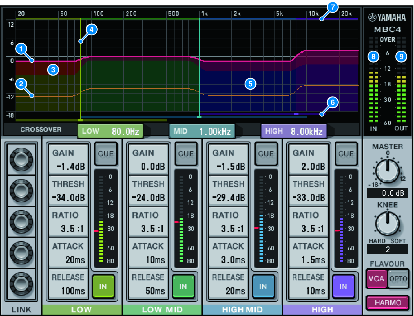
- ① GAIN LINE
-
This red horizontal line indicates the GAIN parameter values for the corresponding band.
- ② MAXIMUM GR GUIDELINE
-
This orange horizontal line indicates a guideline for the maximum gain reduction. This amount is approximate, and does not necessarily show a precise maximum gain reduction amount.
- ③ GR ZONE
-
This red area changes according to the gain reduction amount for the corresponding band.
- ④ CROSSOVER LINE
-
This vertical line indicates the crossover point for the corresponding band.
- ⑤ CROSSOVER ZONE
-
This band-color area changes according to the CROSSOVER parameter value for the corresponding band.
- ⑥ CROSSOVER RANGE
-
This band-color horizontal bar graph indicates a variable range of the CROSSOVER parameter value for the corresponding band.
- ⑦ CROSSOVER BAND WIDTH
-
This band-color horizontal bar graph changes according to the CROSSOVER parameter value for the corresponding band.
- ⑧ INPUT METER
-
Shows the level of the input signal. One meter is shown in the case of DUAL, and two meters in the case of STEREO.
- ⑨ OUTPUT METER
-
Shows the level of the output signal. One meter is shown in the case of DUAL, and two meters in the case of STEREO.
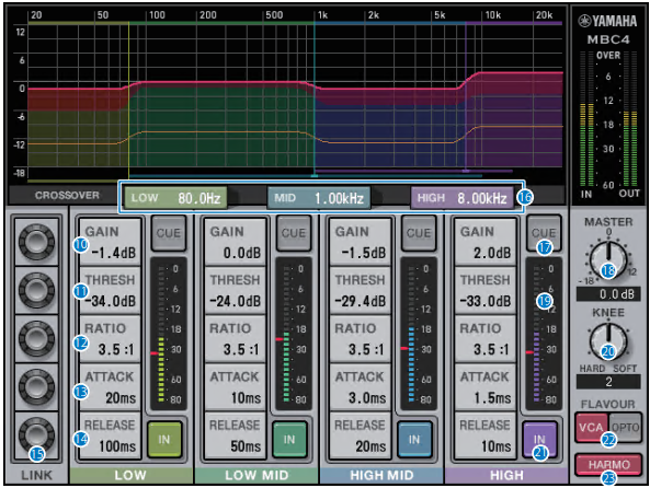
- ⑩ GAIN
-
Adjusts the output gain for the corresponding band.
- ⑪ THRESHOLD
-
Adjusts the level at which the compressor begins to apply for the corresponding band. The value will be also indicated by a red marker on the INPUT meter.
- ⑫ RATIO
-
Adjusts the compression ratio for the corresponding band.
- ⑬ ATTACK
-
Adjusts the attack time at which the compressor begins to apply for the corresponding band.
- ⑭ RELEASE
-
Adjusts the release time of the compressor for the corresponding band.
- ⑮ LINK KNOB
-
If you select the parameter’s LINK knob, the display color will change as shown below. The corresponding parameters for four bands will link together, and the values will change collectively. Note that if the parameter value of one of the bands reaches the maximum or minimum, the link operation will stop. Parameters that can be linked are displayed in the corresponding band color.
- ⑯ CROSSOVER
-
Adjusts the crossover frequencies used to divide the signal into bands.
- ⑰ CUE BUTTON
-
Press this button to cue-monitor the output of the corresponding band. If the IN button is off, a signal without compressor effects will be monitored. You can turn on the CUE buttons for multiple bands.
- ⑱ MASTER GAIN KNOB
-
Adjusts the gain of the final output signal.
- ⑲ INPUT METER
-
Displays the level of the audio signal input to each band.
- ⑳ KNEE KNOB
-
Adjusts the knee of the compressor.
- ㉑ IN BUTTON
-
Switches the compressor on/off for the corresponding band. Even if this button is off, you will be able to adjust the corresponding band parameters.
- ㉒ FLAVOUR BUTTON
-
Switches the type of the compressor between VCA (accurate effects) and OPTO (natural effects).
- ㉓ HARMONICS BUTTON
-
Switches on/off musical harmonics that emulate analog circuitry.
