
Names and Functions
4. Names and Functions
In this manual, the names printed on the panel appear in square brackets (e.g., [INPUT]).
4.1. RUio1608SB-D
4.1.1. Front panel
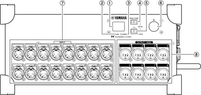
①
Display
The display shows information such as the parameter values for the head amp, or error and status indications.
②
[+48V]
This indicator lights when +48 V phantom power is turned on for any of the INPUT channels. Phantom power for each INPUT channel can be switched on or off using the front-panel display of the unit or via a supported device. While phantom power that is set to on is temporarily turned off, the indicator changes from steady to blinking.
Related link(s)
“
+48V screen
”
“
Setting the INPUT Channel Parameters
”
 WARNING
Make sure that all output controls on the digital mixing console are set to minimum when turning phantom power on or off. Sudden high level peaks caused by the switching operation can damage equipment as well as the hearing of those present.
 NOTICE
To prevent malfunction and noise in this product and external devices, note the following when turning phantom power on or off.
-
If phantom power is not required, you must turn it off.
-
Before connecting a device (that does not support phantom power) to the [INPUT] or [FLEXIBLE I/O] (input) connectors, turn phantom power off.
-
While phantom power is on, do not connect or disconnect cables to the [INPUT] or [FLEXIBLE I/O] (input) connectors.
-
Make sure that all output controls are set to minimum when turning phantom power on or off.
-
To prevent possible damage to speakers, make sure that power amplifiers and/or powered speakers are turned off when switching phantom power on or off.
 NOTE
NOTE
Phantom power to the entire device is always on. For instructions on how to temporarily turn off the phantom power, refer to the NOTE on the “ +48V screen ”.
③
[POWER]
This indicator lights when the power to this product is on.
In addition, the following functions are available:
■ Displaying the METER screens and +48V screen
Press the [MENU/HOME] key and the [
 ] (Back) / [PEAK] key (⑤) simultaneously to display the METER screens and the +48V screen.
Related link(s)
“
METER Screens / +48V Screen
”
■ Displaying a pop-up screen for setting or unlocking the panel lock
Press and hold the [MENU/HOME] key and the [
] (Back) / [PEAK] key (⑤) simultaneously for more than three seconds to display a pop-up screen for setting or unlocking the panel lock.
Related link(s)
“
Locking the Panel
”
“
Unlocking the Panel
”
■ Initializing the contrast/brightness settings
Press and hold the [MENU/HOME] key to initialize the contrast/brightness settings.
The Contrast/Brightness adjustment pop-up screen appears at the same time, allowing you to adjust the settings by turning the encoder with switch.
Related link(s)
“
Adjusting the Contrast and Brightness
”
■ Displaying the status of the unit
You can display the status of the unit.
You can change the light settings that indicate a normal or abnormal status as shown below.
Normal status
You can change the light color, and whether the light is on or off.
|
Light |
Lights up blue. |
|
Lights up green. |
|
|
Off |
Not lit. |
Abnormal status
You can select the settings below to adjust system response when a fatal error occurs (Error) or when an abnormality exists but you can continue using the unit (Caution).
|
Light |
Error |
Lights up red. (You cannot change the color.) |
|
Caution |
Lights up orange. (You cannot change the color.) |
|
|
Flash |
Error |
Red + Normal status setting (blue) |
|
Red + Normal status setting (green) |
||
|
Red + Normal status setting (not lit) |
||
|
Caution |
Orange + Normal status setting (blue) |
|
|
Orange + Normal status setting (green) |
||
|
Orange + Normal status setting (not lit) |
||
|
Abnormal status colors (red and orange): Off
|
Error/Caution |
Lights up in the color selected for normal status (blue) |
|
Lights up in the color selected for normal status (green) |
||
|
Not lit. |
Related link(s)
“
Changing the [MENU/HOME] Key Setting for Normal Status
”
“
Changing the [MENU/HOME] Key Setting for Error Status
”
⑤
[
] (Back) / [PEAK]
Press this key to display the previous screen. If the input level is −3 dBFS or higher in any of the INPUT channels, this key indicator lights up red.
Press and hold this key when a METER screen is displayed to clear PEAK HOLD.
NOTE
Press and hold this key and the [MENU/HOME] key simultaneously for more than three seconds to display a pop-up screen for setting or unlocking the panel lock. (See “ Locking the Panel ” and “ Unlocking the Panel ”.)
⑥
Encoder with switch
By turning this encoder, you can select a menu or parameter. By pressing it, you can confirm a selection or switch the display.
Additionally, pressing and holding this encoder when the +48V screen is displayed will temporarily turn off the phantom power to the entire device while the button is pressed. Moreover, the message “+48V ACTIVE TEMPORARY OFF” will be displayed on the screen.
⑦
[INPUT] 1 to 16
These are balanced XLR 3-hole chassis input connectors that enable you to input analog signals to each channel. The rated input level range is from −60 dBu to +4 dBu. Phantom power (+48V) can be supplied to devices that require it via the input connectors.
⑧
[OUTPUT] 1 to 8
These are balanced XLR 3-pin chassis output connectors that enable you to output analog signals from each channel. The rated output level is +4 dBu.
Device Identify function
When the Device Identify function is used, the display and the [+48V] indicator will flash. At the same time, the [MENU/HOME] key and the [
] (Back) / [PEAK] key will flash green.
For details, see “
Identifying This Product among the Devices in the Network
”.
4.1.2. Side panel
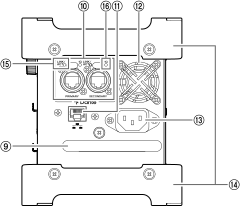
⑨
Handle
Grab this handle to lift this product.
⑩
Dante [PRIMARY] / [SECONDARY]
These etherCON (RJ-45) connectors can be connected to Dante devices using Ethernet cables (CAT5e or higher recommended).
If SECONDARY port (*) is set to DAISY CHAIN, the signal that is input from one connector is transmitted to the other connector.
If SECONDARY port (*) is set to REDUNDANT, the Dante [PRIMARY] connector is used for the primary connection and the Dante [SECONDARY] connector is used for the secondary (backup) connection. If the unit is unable to transmit signals through the Dante [PRIMARY] connector for some reason (e.g., due to damage or accidental removal of the cable, or a failed network switch), the Dante [SECONDARY] connector will automatically take over the connection. (* To display the SECONDARY port setting screen, first, display the MENU TOP screen, select SETUP, and then confirm your selection. Next, select SEC.PORT (SECONDARY PORT) from the SETUP menu, and then confirm your selection.)
Related link(s)
“
About Connections
”
“
SETUP menu
”
NOTE
-
We recommend using RJ-45 plugs that are compatible with Neutrik etherCON CAT5e connectors. Standard RJ-45 plugs can also be used.
-
Connect only Dante-compatible devices or Giga-bit Ethernet (GbE)-compatible devices (including a computer).
-
If using a Dante network, do not use the EEE function of the network switch. The EEE function may deteriorate the clock synchronization performance and interrupt audio.
For details, see NOTE titled “ About Dante ”.
⑪
Network connector
This RJ-45 connector allows the unit to be connected to a computer via an Ethernet cable (CAT5 or higher recommended).
⑫
Cooling vent
This product is equipped with a cooling fan. This vent lets warm air escape from the unit. Do not block the vent with any object.
CAUTION
Do not block the ventilation ports on this product. To prevent internal temperature rise, this product has ventilation holes on the front/back (RUio0804-D, RUio16FLX-D) and sides (RUio1608SB-D). If the ventilation ports are blocked, heat will get trapped inside the product, which may cause malfunction or fire.
⑬
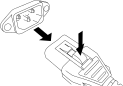
AC IN connector
Use this socket to connect the supplied power cord. First connect the AC power cord to this connector, and then insert the power cord plug into an AC outlet to turn on the power to the unit. Remove the power cord plug from the AC outlet to turn off the power to the unit.
CAUTION
|
Insert each cord plug all the way until it locks in place securely.
|
|
NOTICE
After turning the unit off, wait at least six seconds before turning it on again. Do not turn power to the unit on and off in rapid succession. Doing so can cause it to malfunction.
⑭
Protector
This product can be stacked up to two levels. Stack this product on its protective part. Remove the protectors when rack mounting.
CAUTION
Do not use in unstable locations. Use this product in accordance with the “Safety Precautions” described in “Read This First”.
⑮
[LINK/ACT]
These indicators show the communication status of the Dante [PRIMARY] and Dante [SECONDARY] connectors respectively.
They flash fast if the Ethernet cables are connected properly.
⑯
[1G]
These indicators light when the Dante network is functioning as Giga-bit Ethernet.
4.2. RUio0804-D
4.2.1. Front panel

①
[INPUT] 1 to 8
These are balanced XLR 3-hole chassis input connectors that enable you to input analog signals to each channel. The rated input level range is from −60 dBu to +4 dBu. Phantom power (+48V) can be supplied to devices that require it via the input connectors.
②
[OUTPUT] 1 to 4
These are balanced XLR 3-pin chassis output connectors that enable you to output analog signals from each channel. The rated output level is +4 dBu.
③
Display
The display shows information such as the parameter values for the head amp, or error and status indications.
④
[+48V]
This indicator lights when +48 V phantom power is turned on for any of the INPUT channels. Phantom power for each INPUT channel can be switched on or off using the front-panel display of the unit or via a supported device. While phantom power that is set to on is temporarily turned off, the indicator changes from steady to blinking.
Related link(s)
“
+48V screen
”
“
Setting the INPUT Channel Parameters
”
WARNING
Make sure that all output controls on the digital mixing console are set to minimum when turning phantom power on or off. Sudden high level peaks caused by the switching operation can damage equipment as well as the hearing of those present.
NOTICE
To prevent malfunction and noise in this product and external devices, note the following when turning phantom power on or off.
-
If phantom power is not required, you must turn it off.
-
Before connecting a device (that does not support phantom power) to the [INPUT] or [FLEXIBLE I/O] (input) connectors, turn phantom power off.
-
While phantom power is on, do not connect or disconnect cables to the [INPUT] or [FLEXIBLE I/O] (input) connectors.
-
Make sure that all output controls are set to minimum when turning phantom power on or off.
-
To prevent possible damage to speakers, make sure that power amplifiers and/or powered speakers are turned off when switching phantom power on or off.
NOTE
Phantom power to the entire device is always on. For instructions on how to temporarily turn off the phantom power, refer to the NOTE on the “ +48V screen ”.
⑤
[POWER]
This indicator lights when the power to this product is on.
⑥
[MENU/HOME]
While the home screen is displayed, press this key to display the MENU TOP screen that enables you to select a menu. While a screen other than the home screen is displayed, press this key to display the home screen.
In addition, the following functions are available:
■ Displaying the METER screens and +48V screen
Press the [MENU/HOME] key and the [
] (Back) / [PEAK] key (⑦) simultaneously to display the METER screens and the +48V screen.
Related link(s)
“
METER Screens / +48V Screen
”
■ Displaying a pop-up screen for setting or unlocking the panel lock
Press and hold the [MENU/HOME] key and the [
] (Back) / [PEAK] key (⑦) simultaneously for more than three seconds to display a pop-up screen for setting or unlocking the panel lock.
Related link(s)
“
Locking the Panel
”
“
Unlocking the Panel
”
■ Initializing the contrast/brightness settings
Press and hold the [MENU/HOME] key to initialize the contrast/brightness settings.
The Contrast/Brightness adjustment pop-up screen appears at the same time, allowing you to adjust the settings by turning the encoder with switch.
Related link(s)
“
Adjusting the Contrast and Brightness
”
■ Displaying the status of the unit
You can display the status of the unit.
You can change the light settings that indicate a normal or abnormal status as shown below.
Normal status
You can change the light color, and whether the light is on or off.
|
Light |
Lights up blue. |
|
Lights up green. |
|
|
Off |
Not lit. |
Abnormal status
You can select the settings below to adjust system response when a fatal error occurs (Error) or when an abnormality exists but you can continue using the unit (Caution).
|
Light |
Error |
Lights up red. (You cannot change the color.) |
|
Caution |
Lights up orange. (You cannot change the color.) |
|
|
Flash |
Error |
Red + Normal status setting (blue) |
|
Red + Normal status setting (green) |
||
|
Red + Normal status setting (not lit) |
||
|
Caution |
Orange + Normal status setting (blue) |
|
|
Orange + Normal status setting (green) |
||
|
Orange + Normal status setting (not lit) |
||
|
Abnormal status colors (red and orange): Off
|
Error/Caution |
Lights up in the color selected for normal status (blue) |
|
Lights up in the color selected for normal status (green) |
||
|
Not lit. |
Related link(s)
“
Changing the [MENU/HOME] Key Setting for Normal Status
”
“
Changing the [MENU/HOME] Key Setting for Error Status
”
⑦
[
] (Back) / [PEAK]
Press this key to display the previous screen. If the input level is −3 dBFS or higher in any of the INPUT channels, this key indicator lights up red.
Press and hold this key when a METER screen is displayed to clear PEAK HOLD.
NOTE
Press and hold this key and the [MENU/HOME] key simultaneously for more than three seconds to display a pop-up screen for setting or unlocking the panel lock. (See “ Locking the Panel ” and “ Unlocking the Panel ”.)
⑧
Encoder with switch
By turning this encoder, you can select a menu or parameter. By pressing it, you can confirm a selection or switch the display.
Additionally, pressing and holding this encoder when the +48V screen is displayed will temporarily turn off the phantom power to the entire device while the button is pressed. Moreover, the message “+48V ACTIVE TEMPORARY OFF” will be displayed on the screen.
Device Identify function
When the Device Identify function is used, the display and the [+48V] indicator will flash. At the same time, the [MENU/HOME] key and the [
] (Back) / [PEAK] key will flash green.
For details, see “
Identifying This Product among the Devices in the Network
”.
4.2.2. Rear panel

⑨
AC IN connector
Use this socket to connect the supplied power cord. First connect the AC power cord to this connector, and then insert the power cord plug into an AC outlet to turn on the power to the unit. Remove the power cord plug from the AC outlet to turn off the power to the unit.
CAUTION
|
Insert each cord plug all the way until it locks in place securely.
|
|
NOTICE
After turning the unit off, wait at least six seconds before turning it on again. Do not turn power to the unit on and off in rapid succession. Doing so can cause it to malfunction.
⑩
Cooling vent
This product is equipped with a cooling fan. This vent lets warm air escape from the unit. Do not block the vent with any object.
CAUTION
Do not block the ventilation ports on this product. To prevent internal temperature rise, this product has ventilation holes on the front/back (RUio0804-D, RUio16FLX-D) and sides (RUio1608SB-D). If the ventilation ports are blocked, heat will get trapped inside the product, which may cause malfunction or fire.
⑪
Network connector
This RJ-45 connector allows the unit to be connected to a computer via an Ethernet cable (CAT5 or higher recommended).
⑫
Dante [PRIMARY] / [SECONDARY]
These etherCON (RJ-45) connectors can be connected to Dante devices using Ethernet cables (CAT5e or higher recommended).
If SECONDARY port (*) is set to DAISY CHAIN, the signal that is input from one connector is transmitted to the other connector.
If SECONDARY port (*) is set to REDUNDANT, the Dante [PRIMARY] connector is used for the primary connection and the Dante [SECONDARY] connector is used for the secondary (backup) connection. If the unit is unable to transmit signals through the Dante [PRIMARY] connector for some reason (e.g., due to damage or accidental removal of the cable, or a failed network switch), the Dante [SECONDARY] connector will automatically take over the connection. (* To display the SECONDARY port setting screen, first, display the MENU TOP screen, select SETUP, and then confirm your selection. Next, select SEC.PORT (SECONDARY PORT) from the SETUP menu, and then confirm your selection.)
Related link(s)
“
About Connections
”
“
SETUP menu
”
NOTE
-
We recommend using RJ-45 plugs that are compatible with Neutrik etherCON CAT5e connectors. Standard RJ-45 plugs can also be used.
-
Connect only Dante-compatible devices or Giga-bit Ethernet (GbE)-compatible devices (including a computer).
-
If using a Dante network, do not use the EEE function of the network switch. The EEE function may deteriorate the clock synchronization performance and interrupt audio.
For details, see NOTE titled “ About Dante ”.
⑬
[LINK/ACT]
These indicators show the communication status of the Dante [PRIMARY] and Dante [SECONDARY] connectors respectively.
They flash fast if the Ethernet cables are connected properly.
⑭
[1G]
These indicators light when the Dante network is functioning as Giga-bit Ethernet.
4.3. RUio16FLX-D
4.3.1. Front panel

①
Display
The display shows information such as the parameter values for the head amp, or error and status indications.
②
[+48V]
This indicator lights when +48 V phantom power is turned on for any of the INPUT channels. Phantom power for each INPUT channel can be switched on or off using the front-panel display of the unit or via a supported device. While phantom power that is set to on is temporarily turned off, the indicator changes from steady to blinking.
Related link(s)
“
+48V screen
”
“
Setting the INPUT Channel Parameters
”
WARNING
Make sure that all output controls on the digital mixing console are set to minimum when turning phantom power on or off. Sudden high level peaks caused by the switching operation can damage equipment as well as the hearing of those present.
NOTICE
To prevent malfunction and noise in this product and external devices, note the following when turning phantom power on or off.
-
If phantom power is not required, you must turn it off.
-
Before connecting a device (that does not support phantom power) to the [INPUT] or [FLEXIBLE I/O] (input) connectors, turn phantom power off.
-
While phantom power is on, do not connect or disconnect cables to the [INPUT] or [FLEXIBLE I/O] (input) connectors.
-
Make sure that all output controls are set to minimum when turning phantom power on or off.
-
To prevent possible damage to speakers, make sure that power amplifiers and/or powered speakers are turned off when switching phantom power on or off.
NOTE
Phantom power to the entire device is always on. For instructions on how to temporarily turn off the phantom power, refer to the NOTE on the “ +48V screen ”.
③
[POWER]
This indicator lights when the power to this product is on.
④
[MENU/HOME]
While the home screen is displayed, press this key to display the MENU TOP screen that enables you to select a menu. While a screen other than the home screen is displayed, press this key to display the home screen.
In addition, the following functions are available:
■ Displaying the METER screens and +48V screen
Press the [MENU/HOME] key and the [
] (Back) / [PEAK] key (⑤) simultaneously to display the METER screens and the +48V screen.
Related link(s)
“
METER Screens / +48V Screen
”
■ Displaying a pop-up screen for setting or unlocking the panel lock
Press and hold the [MENU/HOME] key and the [
] (Back) / [PEAK] key (⑤) simultaneously for more than three seconds to display a pop-up screen for setting or unlocking the panel lock.
Related link(s)
“
Locking the Panel
”
“
Unlocking the Panel
”
■ Initializing the contrast/brightness settings
Press and hold the [MENU/HOME] key to initialize the contrast/brightness settings.
The Contrast/Brightness adjustment pop-up screen appears at the same time, allowing you to adjust the settings by turning the encoder with switch.
Related link(s)
“
Adjusting the Contrast and Brightness
”
■ Displaying the status of the unit
You can display the status of the unit.
You can change the light settings that indicate a normal or abnormal status as shown below.
Normal status
You can change the light color, and whether the light is on or off.
|
Light |
Lights up blue. |
|
Lights up green. |
|
|
Off |
Not lit. |
Abnormal status
You can select the settings below to adjust system response when a fatal error occurs (Error) or when an abnormality exists but you can continue using the unit (Caution).
|
Light |
Error |
Lights up red. (You cannot change the color.) |
|
Caution |
Lights up orange. (You cannot change the color.) |
|
|
Flash |
Error |
Red + Normal status setting (blue) |
|
Red + Normal status setting (green) |
||
|
Red + Normal status setting (not lit) |
||
|
Caution |
Orange + Normal status setting (blue) |
|
|
Orange + Normal status setting (green) |
||
|
Orange + Normal status setting (not lit) |
||
|
Abnormal status colors (red and orange): Off
|
Error/Caution |
Lights up in the color selected for normal status (blue) |
|
Lights up in the color selected for normal status (green) |
||
|
Not lit. |
Related link(s)
“
Changing the [MENU/HOME] Key Setting for Normal Status
”
“
Changing the [MENU/HOME] Key Setting for Error Status
”
⑤
[
] (Back) / [PEAK]
Press this key to display the previous screen. If the input level is −3 dBFS or higher in any of the INPUT channels, this key indicator lights up red.
Press and hold this key when a METER screen is displayed to clear PEAK HOLD.
NOTE
Press and hold this key and the [MENU/HOME] key simultaneously for more than three seconds to display a pop-up screen for setting or unlocking the panel lock. (See “ Locking the Panel ” and “ Unlocking the Panel ”.)
⑥
Encoder with switch
By turning this encoder, you can select a menu or parameter. By pressing it, you can confirm a selection or switch the display.
Additionally, pressing and holding this encoder when the +48V screen is displayed will temporarily turn off the phantom power to the entire device while the button is pressed. Moreover, the message “+48V ACTIVE TEMPORARY OFF” will be displayed on the screen.
Device Identify function
When the Device Identify function is used, the display and the [+48V] indicator will flash. At the same time, the [MENU/HOME] key and the [
] (Back) / [PEAK] key will flash green.
For details, see “
Identifying This Product among the Devices in the Network
”.
4.3.2. Rear panel

⑦
AC IN connector
Use this socket to connect the supplied power cord. First connect the AC power cord to this connector, and then insert the power cord plug into an AC outlet to turn on the power to the unit. Remove the power cord plug from the AC outlet to turn off the power to the unit.
CAUTION
|
Insert each cord plug all the way until it locks in place securely.
|
|
NOTICE
After turning the unit off, wait at least six seconds before turning it on again. Do not turn power to the unit on and off in rapid succession. Doing so can cause it to malfunction.
⑧
Cooling vent
This product is equipped with a cooling fan. This vent lets warm air escape from the unit. Do not block the vent with any object.
CAUTION
Do not block the ventilation ports on this product. To prevent internal temperature rise, this product has ventilation holes on the front/back (RUio0804-D, RUio16FLX-D) and sides (RUio1608SB-D). If the ventilation ports are blocked, heat will get trapped inside the product, which may cause malfunction or fire.
⑨
Network connector
This RJ-45 connector allows the unit to be connected to a computer via an Ethernet cable (CAT5 or higher recommended).
⑩
Dante [PRIMARY] / [SECONDARY]
These etherCON (RJ-45) connectors can be connected to Dante devices using Ethernet cables (CAT5e or higher recommended).
If SECONDARY port (*) is set to DAISY CHAIN, the signal that is input from one connector is transmitted to the other connector.
If SECONDARY port (*) is set to REDUNDANT, the Dante [PRIMARY] connector is used for the primary connection and the Dante [SECONDARY] connector is used for the secondary (backup) connection. If the unit is unable to transmit signals through the Dante [PRIMARY] connector for some reason (e.g., due to damage or accidental removal of the cable, or a failed network switch), the Dante [SECONDARY] connector will automatically take over the connection.
(* To display the SECONDARY port setting screen, first, display the MENU TOP screen, select SETUP, and then confirm your selection. Next, select SEC.PORT (SECONDARY PORT) from the SETUP menu, and then confirm your selection.)
Related link(s)
“
About Connections
”
“
SETUP menu
”
NOTE
-
We recommend using RJ-45 plugs that are compatible with Neutrik etherCON CAT5e connectors. Standard RJ-45 plugs can also be used.
-
Connect only Dante-compatible devices or Giga-bit Ethernet (GbE)-compatible devices (including a computer).
-
If using a Dante network, do not use the EEE function of the network switch. The EEE function may deteriorate the clock synchronization performance and interrupt audio.
For details, see NOTE titled “ About Dante ”.
⑪
[FLEXIBLE I/O] connector
These connectors can conveniently be switched between balanced analog input/output and AES/EBU format digital output. Connect line-level devices or microphones to the INPUT, and line-level devices to the OUTPUT. The INPUT has a built-in head amp and can also supply phantom power (+48V). For setup instructions, see “
F16 CONFIG
” in “
SETUP menu
”. For installation instructions, see “
Installing Euroblock Plugs (RUio16FLX-D)
”.
⑫
[LINK/ACT]
These indicators show the communication status of the Dante [PRIMARY] and Dante [SECONDARY] connectors respectively.
They flash fast if the Ethernet cables are connected properly.
⑬
[1G]
These indicators light when the Dante network is functioning as Giga-bit Ethernet.