
Reference
12. Reference
12.1. Message List
The front panel displays various messages such as SYSTEM, SYNC, errors, warnings, information, and confirmations.
12.1.1. SYSTEM messages
The status display shown in the SYSTEM messages indicates the operating status of this product.
 NOTE
NOTE
-
If the ID is blank in the table below, only the message will appear on the display.
| ID | Display on This Product | Display on R Remote | Description | Possible Solution |
|---|---|---|---|---|
|
NORMAL |
--- |
Operating normally. |
--- |
|
|
E00-003 |
DANTE MODULE ERROR! |
DANTE module error! |
An error has occurred in the Dante module. |
Restart this unit. |
|
E00-004 |
ILLEGAL MAC ADDRESS! (CONTACT US) |
Illegal MAC Address! |
Because the MAC Address setting has been damaged, communication is not possible. |
Contact your Yamaha dealer. |
|
E00-005 |
UNIT FAN HAS MALFUNCTIONED! (CONTACT US) |
Unit Fan has Malfunctioned! |
The cooling fan has stopped. |
Check to see if there is anything stuck in the fan. If this does not solve the problem, contact your Yamaha dealer. |
|
E00-006 |
MEMORY ERROR! |
Memory Error. |
Failed to read from non-volatile memory. |
Information that was saved during the previous operation was lost. You must configure the settings again. |
|
E00-009 |
VERSION MISMATCH WITH DANTE MODULE! |
Version mismatch. |
The unit’s firmware and the Dante firmware are not compatible. This unit’s firmware and the supported digital mixer’s firmware are not compatible. |
Acquire compatible versions. |
|
E00-010 |
DANTE AUDIO RESOURCE OVERFLOW! |
DANTE audio resource overflow. |
The number of Dante flows has exceeded the limit. |
Re-configure the Dante audio routing, for example by eliminating unneeded routings, or by using multicast rather than unicast to improve the efficiency. |
12.1.2. SYNC messages
The status display shown in the SYNC messages indicates the Dante network status.
NOTE
-
If the ID is blank in the table below, only the message will appear on the display.
| ID | Message | Description | Explanation or possible solution |
|---|---|---|---|
|
NORMAL |
Functioning correctly as a word clock follower. |
This indicates that the device is a word clock follower. |
|
|
DANTE WORDCLOCK LEADER |
Functioning correctly as the word clock leader. |
This indicates that the device is the word clock leader. |
|
|
SYNCHRONIZING WITH CONSOLE OR CONTROLLER |
Currently processing synchronization within the Dante network. |
Wait until startup or synchronization is completed. It may take up to 45 seconds for this to be completed. |
|
|
E01-003 |
WRONG WORDCLOCK! |
The word clock setting is incorrect. |
On the supported digital mixer or in Dante Controller, set the clock leader and the sampling frequency correctly. |
|
E01-004 |
DANTE PORT DOES NOT HAVE CONNECTION! |
The Dante network is not connected. |
Check whether an Ethernet cable might be disconnected or broken. |
|
E01-005 |
DANTE CONNECTION ERROR! |
Other Dante devices cannot be found because the Dante network connections are incorrect. |
Check whether the Ethernet cable connections are correct. |
|
E01-006 |
DANTE IS NOT WORKING BY GIGA BIT! |
A device that does not support Giga-bit Ethernet is connected. |
If you are transferring audio via Dante, use devices that support Giga-bit Ethernet. |
|
E01-007 |
DANTE IS WORKING AT SECONDARY! |
In the case of a redundant network, communication is occurring via the Dante [SECONDARY] connector. |
Check the circuit that is connected to the Dante [PRIMARY] connector. |
|
E01-008 |
ERROR OCCURRED AT SECONDARY PORT! |
In the case of a redundant network, a problem has occurred in the circuit that is connected to the Dante [SECONDARY] connector. |
Check the circuit that is connected to the Dante [SECONDARY] connector. |
|
E01-010 |
DANTE IS NOT WORKING BY GIGA BIT! |
Functioning as the word clock leader. A device that does not support Giga-bit Ethernet is connected. |
This indicates that the device is the word clock leader.
|
|
E01-011 |
DANTE IS WORKING AT SECONDARY! |
Functioning as the word clock leader. In the case of a redundant network, communication is occurring via the Dante [SECONDARY] connector. |
This indicates that the device is the word clock leader.
|
|
E01-012 |
ERROR OCCURRED AT SECONDARY PORT! |
Functioning as the word clock leader. In the case of a redundant network, a problem has occurred in the circuit that is connected to the Dante [SECONDARY] connector. |
This indicates that the device is the word clock leader.
|
12.1.3. Error messages
| Message | Description | Possible Solution |
|---|---|---|
|
HAAD HARD ERROR! |
A problem with HAAD was detected. |
If the problem persists, contact your Yamaha dealer. |
12.1.4. Warning messages
| Message | Description | Possible Solution |
|---|---|---|
|
DANTE DEVICE LOCK IS ENABLED! |
You may have attempted to change this unit’s UNIT ID or a Dante setting such as SECONDARY PORT while Dante Device Lock was enabled. |
Use Dante Controller to release Dante Device Lock. |
|
DANTE DDM LOCAL POLICY IS READ ONLY! |
You may have attempted to change this unit’s UNIT ID or a Dante setting such as SECONDARY PORT while Local Policy in DDM was set to Read Only. |
Use the DDM setting application to cancel Read Only for Local Policy. |
|
IP ADDRESS DUPLICATED |
The same IP addresses exist on the network.
|
Resolve the IP address conflict. |
|
SAME NET ADDR! (NW PORT & DNT PORT ***) |
There is a network address conflict between the network port and the Dante port. |
Resolve the network address conflict. |
|
SAME NET ADDR! (NW PORT & DNT PRI ***) |
There is a network address conflict between the network port and the PRIMARY port. |
Resolve the network address conflict. |
|
SAME NET ADDR! (NW PORT & DNT SEC ***) |
There is a network address conflict between the network port and the SECONDARY port. |
Resolve the network address conflict. |
|
SAME NET ADDR! (DNT PORT & NW PORT ***) |
There is a network address conflict between the Dante port and the network port. |
Resolve the network address conflict. |
|
SAME NET ADDR! (DNT PORT & DNT PRI ***) |
There is a network address conflict between the Dante port and the PRIMARY port. |
Resolve the network address conflict. |
|
SAME NET ADDR! (DNT PORT & DNT SEC ***) |
There is a network address conflict between the Dante port and the SECONDARY port. |
Resolve the network address conflict. |
“***” represents the conflicting network address.
12.1.5. Information messages
| Message | Description |
|---|---|
|
FRONT PANEL LOCKED |
Panel Lock has been enabled. |
|
FRONT PANEL UNLOCKED |
Panel Lock is now disabled. |
|
REMOTE ONLY LOCAL CONTROL IS DISABLED |
The parameters for the INPUT/OUTPUT channels are read-only. |
|
AUDIO MUTED NO SYNC WITH MIXER OR APP |
Muted. |
|
DAISY CHAIN SECONDARY PORT |
The SECONDARY port has been set to DAISY CHAIN. |
|
FACTORY INITIALIZE ACCEPTED! |
Initialization of the unit (restoring the factory settings) has begun. |
|
+48V ACTIVE TEMPORARY OFF |
The phantom power is temporarily off. |
12.1.6. Confirmation messages
| Message | Description |
|---|---|
|
FACTORY PRESET INITIALIZE? |
Initialize the unit (restore the factory settings)? |
|
INITIALIZE DONE. REBOOT? |
Finished initializing the unit (restoring the factory settings). Restart the unit? |
|
CURRENT PARAMETERS INITIALIZE? |
Start HA initialization? |
|
DANTE SETTINGS INITIALIZE? |
Start initializing the Dante settings? |
|
RESTART THE SYSTEM? |
Restart the unit? |
12.2. General Specifications
The contents of this manual apply to the latest specifications as of the publishing date. To obtain the latest manual, access the Yamaha website then download the manual file.
| RUio1608SB-D | RUio0804-D | RUio16FLX-D | ||
|---|---|---|---|---|
|
Number of Analog Inputs |
16 |
8 |
16 |
|
|
Number of Analog Outputs |
8 |
4 |
16 |
|
|
AES/EBU Output |
0 |
0 |
16 |
|
|
Sampling Frequency |
44.1 kHz / 48 kHz / 88.2 kHz / 96 kHz ±200 ppm
|
|||
|
Signal Delay |
Less than 1.7 ms@Fs=96 kHz, 2.0 ms@Fs=48 kHz
|
|||
|
Power Requirements |
100–240 V, 50 Hz/60 Hz |
|||
|
Power Consumption |
40 W |
30 W |
45 W |
|
|
Heat Dissipation |
35 kcal/h |
26 kcal/h |
39 kcal/h |
|
|
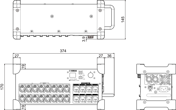
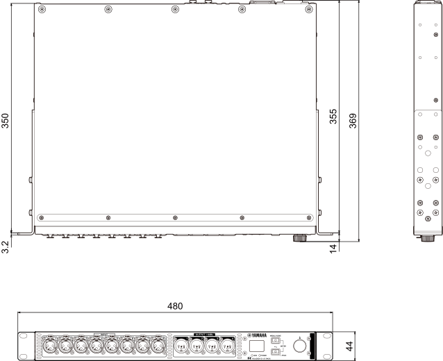
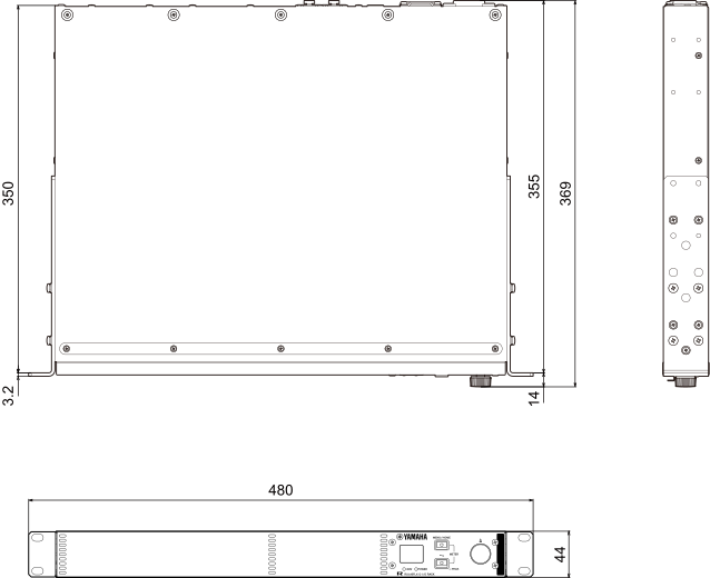
Dimensions |
W × H × D |
374 × 170 × 145 mm |
480 × 44 × 369 mm |
|
|
Weight |
3.5 kg |
3.7 kg |
4.0 kg |
|
|
NC value *1 |
Fan Speed LOW |
20 |
20 |
20 |
|
Fan Speed HIGH |
25 |
25 |
25 |
|
|
Approximate Munsell value of exterior color |
N5 (RUio0804-D, RUio16FLX-D: Front Panel only) |
|||
|
Operating Temperature Range |
0 °C to 40 °C |
|||
|
Storage Temperature Range |
−20 °C to 60 °C |
|||
|
Included Accessories |
Read This First × 1, Power cord × 1 *2 , 3-Pin Euroblock plugs × 16 (only for RUio16FLX-D), Cable ties × 16 (only for RUio16FLX-D) |
|||
*1 Measurement position: 1 m from the front of the unit
*2 Multiple AC power cords which have different kinds of plug shapes may be included depending on the region.
12.3. Audio Characteristics
During the measurement, the output impedance of the signal generator is 150 Ω. The output load impedance is 10 kΩ. Where specifications for the RUio1608SB-D differ from the RUio0804-D, this manual places specifications that apply only to the RUio0804-D in curly brackets { }.
12.3.1. Frequency response
Fs=96 kHz or Fs=48 kHz @20 Hz–20 kHz, reference to the nominal output level @1 kHz
RUio1608SB-D, RUio0804-D
| Input | Output | RL | Conditions | Min. | Typ. | Max. | Unit |
|---|---|---|---|---|---|---|---|
|
INPUT 1–16 {1–8} |
OUTPUT 1–8 {1–4} |
10 kΩ |
GAIN: +64 dB |
−1.5 |
0.0 |
0.5 |
dB |
RUio16FLX-D
| Input | Output | RL | Conditions | Min. | Typ. | Max. | Unit |
|---|---|---|---|---|---|---|---|
|
INPUT 1–16 |
OUTPUT 1–16 |
10 kΩ |
GAIN: +64 dB |
−1.5 |
0.0 |
0.5 |
dB |
12.3.2. Total harmonic distortion
Fs=96 kHz or Fs=48 kHz
RUio1608SB-D, RUio0804-D
| Input | Output | RL | Conditions | Min. | Typ. | Max. | Unit |
|---|---|---|---|---|---|---|---|
|
INPUT 1–16 {1–8} |
OUTPUT 1–8 {1–4} |
10 kΩ |
+4 dBu@20 Hz–20 kHz, GAIN: +64 dB |
0.15 |
% |
||
|
INPUT 1–16 {1–8} |
OUTPUT 1–8 {1–4} |
10 kΩ |
+4 dBu@20 Hz–20 kHz, GAIN: 0 dB |
0.05 |
% |
* Total harmonic distortion was measured using an 80 kHz, 48 dB/octave low pass filter.
RUio16FLX-D
| Input | Output | RL | Conditions | Min. | Typ. | Max. | Unit |
|---|---|---|---|---|---|---|---|
|
INPUT 1–16 |
OUTPUT 1–16 |
10 kΩ |
+4 dBu@20 Hz–20 kHz, GAIN: +64 dB |
0.15 |
% |
||
|
INPUT 1–16 |
OUTPUT 1–16 |
10 kΩ |
+4 dBu@20 Hz–20 kHz, GAIN: 0 dB |
0.05 |
% |
* Total harmonic distortion was measured using an 80 kHz, 48 dB/octave low pass filter.
12.3.3. Hum & Noise
Fs=96 kHz or Fs=48 kHz
RUio1608SB-D, RUio0804-D
EIN=Equivalent Input Noise
| Input | Output | RL | Conditions | Min. | Typ. | Max. | Unit |
|---|---|---|---|---|---|---|---|
|
INPUT 1–16 {1–8} |
OUTPUT 1–8 {1–4} |
10 kΩ |
Rs=150 Ω, GAIN: +64 dB |
−128
|
dBu |
||
|
−64 |
dBu |
||||||
|
INPUT 1–16 {1–8} |
OUTPUT 1–8 {1–4} |
10 kΩ |
Rs=150 Ω, GAIN: 0 dB |
−85 |
−83 |
dBu |
|
|
All Inputs |
OUTPUT 1–8 {1–4} |
10 kΩ |
Rs=150 Ω, GAIN: 0 dB
|
−71 {−74} |
dBu |
||
|
- |
OUTPUT 1–8 {1–4} |
10 kΩ |
Residual output noise, Main stereo channel off. |
−90 |
−88 |
dBu |
* Hum & noise levels were measured using an A-weight filter.
RUio16FLX-D
EIN=Equivalent Input Noise
| Input | Output | RL | Conditions | Min. | Typ. | Max. | Unit |
|---|---|---|---|---|---|---|---|
|
INPUT 1–16 |
OUTPUT 1–16 |
10 kΩ |
Rs=150 Ω, GAIN: +64 dB |
−128
|
dBu |
||
|
−64 |
dBu |
||||||
|
INPUT 1–16 |
OUTPUT 1–16 |
10 kΩ |
Rs=150 Ω, GAIN: 0 dB |
−85 |
−83 |
dBu |
|
|
All Inputs |
OUTPUT 1–16 |
10 kΩ |
Rs=150 Ω, GAIN: 0 dB
|
−71 |
dBu |
||
|
- |
OUTPUT 1–16 |
10 kΩ |
Residual output noise, Main stereo channel off. |
−90 |
−88 |
dBu |
* Hum & noise levels were measured using an A-weight filter.
12.3.4. Dynamic range
Fs=96 kHz or Fs=48 kHz
RUio1608SB-D, RUio0804-D
| Input | Output | RL | Conditions | Min. | Typ. | Max. | Unit |
|---|---|---|---|---|---|---|---|
|
INPUT 1–16 {1–8} |
OUTPUT 1–8 {1–4} |
10 kΩ |
AD+DA, GAIN: 0 dB |
109 |
dB |
||
|
- |
OUTPUT 1–8 {1–4} |
10 kΩ |
DA Converter |
114 |
dB |
* Dynamic range was measured using an A-weight filter.
RUio16FLX-D
| Input | Output | RL | Conditions | Min. | Typ. | Max. | Unit |
|---|---|---|---|---|---|---|---|
|
INPUT 1–16 |
OUTPUT 1–16 |
10 kΩ |
AD+DA, GAIN: 0 dB |
109 |
dB |
||
|
- |
OUTPUT 1–16 |
10 kΩ |
DA Converter |
114 |
dB |
* Dynamic range was measured using an A-weight filter.
12.3.5. Crosstalk (@1 kHz)
RUio1608SB-D, RUio0804-D
| From/To | To/From | Conditions | Min. | Typ. | Max. | Unit |
|---|---|---|---|---|---|---|
|
INPUT N |
INPUT (N-1) or (N+1) |
INPUT 1–16 {1–8}, adjacent inputs, GAIN: 0 dB |
−100 |
dB |
||
|
OUTPUT N |
OUTPUT (N-1) or (N+1) |
OUTPUT 1–8 {1–4}, input to output |
−100 |
dB |
* Crosstalk was measured using a 22 kHz, 48 dB/octave filter.
RUio16FLX-D
| From/To | To/From | Conditions | Min. | Typ. | Max. | Unit |
|---|---|---|---|---|---|---|
|
INPUT N |
INPUT (N-1) or (N+1) |
INPUT 1–16, adjacent inputs, GAIN: 0 dB |
−100 |
dB |
||
|
OUTPUT N |
OUTPUT (N-1) or (N+1) |
OUTPUT 1–16, input to output |
−100 |
dB |
* Crosstalk was measured using a 22 kHz, 48 dB/octave filter.
12.4. Analog Input Standards *3 *4
|
Input Terminal |
GAIN |
Actual Load
|
For Use with
|
Input Level |
Connector |
||
|---|---|---|---|---|---|---|---|
|
Sensitivity *1 |
Nominal |
Max.
|
|||||
|
INPUT 1–16 {1–8} |
+64 dB |
10 kΩ |
50–600 Ω Mics
|
−80 dBu
|
−60 dBu
|
−40 dBu
|
XLR 3-hole chassis (Balanced)
*2
|
|
0 dB |
−16 dBu
|
+4 dBu
|
+24 dBu
|
||||
*1 Sensitivity is the minimum level needed to output +4 dBu (1.23 V) or the specified level when the gain is set to
maximum. (All faders and level controls are set to maximum.)
*2 1=GND, 2=HOT, 3=COLD
*3 0 dBu = 0.775 Vrms
*4 +48V DC (phantom power) is supplied to INPUT XLR type connectors via each individual software-controlled switch.
*5 Only RUio16FLX-D
12.5. Analog Output Standards *2
RUio1608SB-D, RUio0804-D
|
Output Terminal |
Actual Source Impedance |
For Use with Nominal |
Output Level *3 |
Connector |
|
|---|---|---|---|---|---|
|
Nominal |
Max. before clip |
||||
|
OUTPUT 1–8 {1–4} |
75 Ω |
10 kΩ Lines |
+4 dBu
|
+24 dBu
|
XLR 3-pin chassis (Balanced) *1 |
*1 1=GND, 2=HOT, 3=COLD
*2 0 dBu = 0.775 Vrms
*3 You can change the output level for the OUTPUT 1–8 {1–4} connectors. Contact your Yamaha dealer.
RUio16FLX-D
|
Output Terminal |
Actual Source Impedance |
For Use with Nominal |
Output Level *3 |
Connector |
|
|---|---|---|---|---|---|
|
Nominal |
Max. before clip |
||||
|
OUTPUT 1–16 |
75 Ω |
10 kΩ Lines |
+4 dBu
|
+24 dBu
|
Euroblock (3.5 mm pitch) (Balanced) |
*2 0 dBu = 0.775 Vrms
*3 You can change the output level for the OUTPUT 1–16 connectors. Contact your Yamaha dealer.
12.6. Digital I/O Standards
| Terminal | Format | Data length | Level | Audio | Connector |
|---|---|---|---|---|---|
|
Dante
|
Dante |
24-bit / 32-bit |
1000BASE-T |
16ch TX / 8ch RX
*2
|
etherCON CAT5e *1 |
|
AES/EBU *4 |
AES/EBU
|
24-bit |
RS-422 |
16ch output |
Euroblock (3.5 mm pitch) (Balanced) *4 |
*1 CAT5e or higher cables are recommended for connections.
*2 RUio1608SB-D
*3 RUio0804-D
*4 RUio16FLX-D
12.7. Control I/O Standards
| Terminal | Format | Level | Connector |
|---|---|---|---|
|
NETWORK |
IEEE802.3 |
1000BASE-T/100BASE-TX |
RJ-45 *1 |
*1 CAT5e or higher cables are recommended for connections.
12.9. Troubleshooting
The Yamaha Pro Audio website provides a FAQ (frequently asked questions and answers).
https://www.yamahaproaudio.com/
| Symptom | Cause | Possible Solution |
|---|---|---|
|
The power won’t turn on. The [POWER] indicator does not light. |
The power cable is connected improperly. |
Connect the power cable properly (see the AC IN connector section in “ Names and Functions ”). |
|
The unit is not receiving an input signal. |
The cables are not connected properly. |
Connect the cables properly. |
|
The internal head amplifier gain is not set to an appropriate level. |
Set the internal head amplifier gain to an appropriate level. |
|
|
START UP mode is set to REFRESH with MUTE, but the supported device has not started up. |
Start the supported device to send the settings to this product. |
|
|
The input level is too low. |
A condenser microphone is connected. |
Turn phantom power for the corresponding channel(s) ON. |
|
The internal head amplifier gain is not set to an appropriate level. |
Set the internal head amplifier gain to an appropriate level. |
|
|
No sound is heard. |
The cables are not connected properly. |
Connect the cables properly. |
|
START UP mode is set to REFRESH with MUTE, but the supported device has not started up. |
Start the supported device to send the settings to this product. |
|
|
The Dante settings for this product are not synchronized with those for the supported device. |
If you are using a supported digital mixer, set CONSOLE ID to #1 to synchronize the settings. If you are using other supported devices, use Dante Controller to synchronize the settings. |
|
|
The head amp cannot be controlled. |
This product has not been mounted on the RACK of the supported device. |
Mount this product on the RACK of the supported device. |
|
Adjusting the internal head amp gain does not change the audio level. |
GC (Gain Compensation) is turned on. |
If you are not using GC (Gain Compensation), turn it off. |
|
Dante Controller does not recognize this product. |
An incorrect value has been assigned to the IP address for Dante. |
Initialize this product. |
|
R Remote does not recognize this product. |
The UNIT ID setting conflicts with another R series unit. |
Specify a unique UNIT ID for each device. |
|
The IP address setting is incorrect. Alternatively, the network is connected incorrectly. |
Review the network settings. Make sure that they are set to the same subnet.
|
|
|
The [POWER] indicator is lit, but nothing appears in the display. |
A malfunction may have occurred. |
Contact your Yamaha dealer. |
|
Keys, switches, or encoder operations do not work. |
Panel Lock is enabled. |
Defeat Panel Lock. |
|
© 2026 Yamaha Corporation
|