
Screens
7. Screens
7.2. Home Screen
UNIT ID, product device label, and status bar are displayed here.
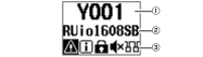
This screen is displayed when you turn on the power switch.
In addition, it is displayed when you press the [MENU/HOME] key while any other screen is displayed.
①
UNIT ID
The upper row on the home screen displays the UNIT ID. The initial value is Y001. You can change this to a value between Y000 and Y07F. To set the UNIT ID, use the UNIT ID parameter in the SETUP menu. (See “
SETUP menu
”.) Changes to the UNIT ID are also reflected immediately in the device label (the last two digits of the first four characters).
②
Device label
The middle row on the home screen displays part of the device label. The first five characters Y0##- (## represents the UNIT ID) and Yamaha- are not displayed. The initial value is up to 10 characters of the model number (e.g., RUio1608SB, RUio0804-D, or RUio16FLX-). The device label can be specified from Dante Controller. Assign the device label as follows.
-
Do not change the first five characters Y0##- (that include the UNIT ID). Even if you try to change these characters, they will automatically be corrected to Y0##-.
-
You can use up to 31 characters total.
③
Status bar
The bottom row on the home screen displays the status bar, which uses icons to indicate the status of the product. Six types of icons are displayed. Turn the encoder with switch to select an icon, and then press the switch to confirm the selection to view the meaning of the icon.
 NOTE
NOTE
Either the PANEL LOCK icon or REMOTE ONLY icon appears in the same location. If both are enabled, the PANEL LOCK icon will be displayed.
Icons appear on the status bar under the following status:
| Icon | Status | Remarks |
|---|---|---|
|
|
An error has occurred. |
The [MENU/HOME] key lights up/flashes simultaneously with the display of the icon. This setting can be changed.
|
|
|
There is a notification. |
|
|
|
Panel Lock has been enabled. |
|
|
|
The HA parameters are set to read-only. |
|
|
|
Muted (all ports together). |
You can change the mute setting at start up in START UP mode. See “ SETUP menu ” or “ Changing the Mute Setting at Start UP ”. |
|
|
The SECONDARY port has been set to DAISY CHAIN. |
You can change this setting to REDUNDANT using the SEC.PORT (SECONDARY PORT) parameter. See “ SETUP menu ”. |


7.3. METER Screens / +48V Screen
The METER screens consist of the IN and OUT screens. Each screen displays a level meter. On the +48V screen, you can turn phantom power (+48V) on or off for each channel.
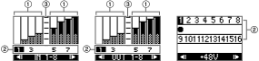
①
Level meter
This area displays the level meter for each channel.
②
Channel number
You can select the channel number by turning the encoder with switch. The selected channel number is highlighted.
③
Scale
From the top, the values are 0, -6, -12, -18, -24, and -40 dB.
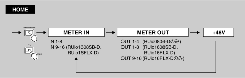
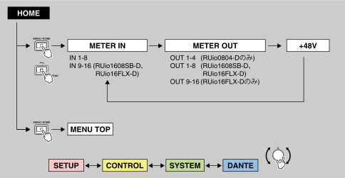
When the home screen is displayed, repeatedly press the [MENU/HOME] key and the [
 ] (Back) / [PEAK] key simultaneously to cycle through the METER IN, METER OUT, and +48V screens.
NOTE
-
On the RUio1608SB-D, each press of the [MENU/HOME] key and the [
] (Back) / [PEAK] key simultaneously cycles the display through the IN 1-8, IN 9-16, OUT 1-8, and +48V screens.
-
On the RUio0804-D, each press of the [MENU/HOME] key and the [
] (Back) / [PEAK] key simultaneously cycles the display through the IN 1-8, OUT 1-4, and +48V screens.
-
On the RUio16FLX-D, each press of the [MENU/HOME] key and the [
] (Back) / [PEAK] key simultaneously cycles the display through the IN 1-8, IN 9-16, OUT 1-8, OUT 9-16, and +48V screens.
-
When selecting a channel number by turning the encoder with switch, keep turning it to move to the next screen.
7.3.1. METER IN
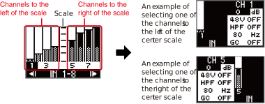
If you select a channel number and then confirm the selection on the METER IN screen, the parameter edit screen will be displayed. You can set the HA gain, +48V ON/OFF, HPF ON/OFF, HPF cutoff frequency, and GC (Gain Compensation) ON/OFF.
Related link(s)
“
Setting the INPUT Channel Parameters
”

7.3.3. +48V screen
On the +48V screen, once you select/confirm a channel number,
 appears below the channel number, and the phantom power (+48V) for the selected channel number is turned on. If phantom power is turned on in any of the INPUT channels, the [+48V] indicator on the front panel lights up.

Pressing the encoder with switch again causes
to disappear and turns off the phantom power. If this setting is turned off for all INPUT channels, the [+48V] indicator turns off.
NOTE
-
Phantom power to the entire device is always on.
-
Pressing and holding the encoder with switch when the +48V screen is displayed will temporarily turn off the phantom power to the entire device while the button is pressed. Moreover, the message “+48V ACTIVE TEMPORARY OFF” will be displayed on the screen.
If any channel has phantom power turned on at that time, the [+48V] indicator will change from steady light to flashing. -
If the phantom power is temporarily turned off while a supported device is connected, the screen indicates that the phantom power to the device is off.
7.4. MENU TOP Screen
This screen enables you to select a menu.
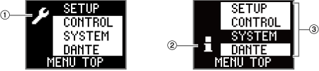
①
SETUP icon
This icon appears when the SETUP menu or CONTROL menu is selected. Both menus enable you to make settings.
②
Information icon
This icon appears when the SYSTEM menu or DANTE menu is selected. Both menus enable you to view information.
③
Menu
This area displays menu options. You can choose SETUP, CONTROL, SYSTEM, or DANTE.
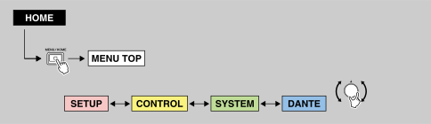
While the home screen is displayed, press the [MENU/HOME] key to display the MENU TOP screen. Turn the encoder with switch to select a menu option, and then press it to confirm.
7.4.1. SETUP menu
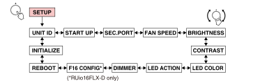
This shows the current values for various setup parameters on this unit.
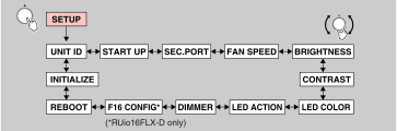
While the SETUP screen is displayed, turn the encoder with switch to select a parameter, and then press it to confirm.
The following table provides a description of the items and parameters that can be selected, and the values that can be set.
| Item | Description | Setting value (* represents the default value.) |
|---|---|---|
|
UNIT ID |
Specifies the unit ID. |
Y000(0) to Y07F(127)
|
|
START UP |
Specifies how the HA parameters will be applied at start up (START UP mode). This setting will be applied the next time the unit starts up.
REFRESH with MUTE:
RESUME w/o MUTE:
REFRESH w/o MUTE:
|
REFRESH with MUTE*, RESUME w/o MUTE, REFRESH w/o MUTE |
|
SEC.PORT
|
Specifies the operating mode of the SECONDARY port. |
DAISY CHAIN*, REDUNDANT |
|
FAN SPEED |
Specifies the rotation speed of the fan. |
LOW*, HIGH |
|
BRIGHTNESS |
Specifies the brightness of the display, [MENU/HOME] key, and [
|
0 to 20
|
|
CONTRAST |
Specifies the display contrast.
|
0 to 20
|
|
LED COLOR |
Specifies the display color of the [MENU/HOME] key. |
OFF, GREEN*, BLUE |
|
LED ACTION |
Specifies the error indicator displayed on the [MENU/HOME] key. |
OFF, BLINK, ON* |
|
DIMMER |
Specifies the time until the backlight turns off.
|
10 sec, 30 sec*, 1 min, 3 min, 30 min, NEVER |
|
Configures the INPUT, OUTPUT, and AES OUT port allocation for the RUio16FLX-D. When you change the INPUT value, the OUTPUT value will automatically change. When you set a value for OUTPUT, the remaining value will be assigned to AES OUT. Once the allocation is confirmed, a confirmation message appears. Pressing [OK] will restart the RUio16FLX-D. |
INPUT: 16*, OUTPUT: 0*, AES OUT: 0*
|
|
|
REBOOT |
Displays the confirmation for restarting. |
RESTART THE SYSTEM |
|
INITIALIZE |
Specifies the type of memory that you want to initialize. Select the memory, and then press the encoder with switch. A confirmation message appears. Press [OK] to perform the initialization.
FACTORY PRESET:
CURRENT PARAMETERS:
DANTE SETTINGS:
For instructions, see “ Performing Initialization ”. |
FACTORY PRESET*, CURRENT PARAMETERS, DANTE SETTINGS |
7.4.2. CONTROL menu
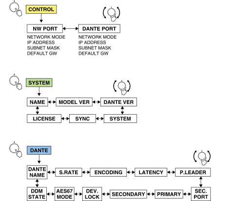
You can view and edit the settings for the two Ethernet ports on the unit.
You can control this product from R Remote or ProVisionaire by using the NW PORT (network port) and/or DANTE PORT (Dante port) for communications. You can use the NW PORT (network port) and DANTE PORT (Dante port) simultaneously when you want to handle the Dante circuit and control circuit separately.
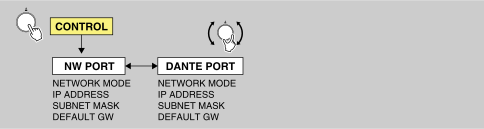
While the CONTROL screen is displayed, turn the encoder with switch to select a parameter, and then press it to confirm.
NOTE
-
Make sure that the network addresses of the NW PORT and DANTE PORT are unique. If you set them to the same address, an error message will appear.
-
Make sure that the network addresses of the NW PORT and Dante PRIMARY/SECONDARY are unique. If you set them to the same address, an error message will appear.
-
Do not set two or more values to DEFAULT GATEWAY. If you set two or more values, only one will be accepted as valid.
◆ NW PORT (Network port)
Network port is used for the control circuit. For more information on communications, see section (3) of “
Communication method
”.
The following table provides a description of the items and parameters that can be selected, and the values that can be set.
| Item | Description | Setting value (* represents the default value.) |
|---|---|---|
|
NETWORK MODE |
Selects the IP address setting mode for the network port. This IP address is used when remotely controlling the unit from a computer, or when updating the firmware. |
DHCP, STATIC IP* |
|
IP ADDRESS |
Specifies the IP address for the network port
|
192.168.0.2*
|
|
SUBNET MASK |
Specifies the SUBNET MASK for the network port
|
255.255.255.0*
|
|
DEFAULT GW |
Specifies the DEFAULT GATEWAY for the network port
|
192.168.0.1*
|
◆ DANTE PORT (Dante port)
Dante port is used for the control circuit. For more information on communications, see section (2) of “
Communication method
”.
The following table provides a description of the items and parameters that can be selected, and the values that can be set.
| Item | Description | Setting value (* represents the default value.) |
|---|---|---|
|
NETWORK MODE |
Selects the IP address setting mode for the Dante port. This IP address is used when remotely controlling the unit from a computer, or when updating the firmware. |
DHCP*, STATIC IP |
|
IP ADDRESS |
Specifies the IP address for the Dante ports
|
(Determined by DHCP or Link Local)* |
|
SUBNET MASK |
Specifies the SUBNET MASK for the Dante port
|
(Determined by DHCP or Link Local)* |
|
DEFAULT GW |
Specifies the DEFAULT GATEWAY for the Dante port
|
(Determined by DHCP or Link Local)* |
7.4.3. SYSTEM menu
This menu displays the unit version number, the SYSTEM/SYNC status, and other information.
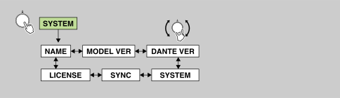
While the SYSTEM screen is displayed, turn the encoder with switch to select a parameter.
The screen displays the following items. Settings cannot be changed on this product.
| Item | Description |
|---|---|
|
NAME |
Indicates the Dante device label. |
|
MODEL VER |
Indicates the firmware version of this product. |
|
DANTE VER |
Indicates the Dante versions. (Dante firmware version, FPGA version, Yamaha software version) |
|
SYSTEM |
Indicates the system status of this product. For details on the messages, see “ SYSTEM messages ”. |
|
SYNC |
Indicates the synchronization status of this product. For details on the messages, see “ SYNC messages ”. |
|
LICENSE |
Indicates the open-source license. Press the encoder with switch to select the license text. When you have selected a license text, you can scroll through the license text by turning the encoder with switch. |
7.4.4. DANTE Menu
This menu displays information for Dante-related settings.
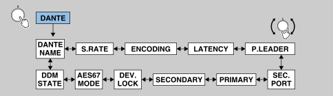
On the DANTE screen, turn the encoder with switch to select a parameter.
The screen displays the following items. Settings cannot be changed on this product.
| Item | Description |
|---|---|
|
DANTE NAME |
Indicates the Dante device label.
|
|
S.RATE
|
Indicates the sampling frequency (Fs) and Pull-Up/Down status. |
|
ENCODING |
Indicates the bit depth. Supports 24-bit and 32-bit.
|
|
LATENCY |
Indicates the latency value. Supports 0.25 ms, 0.5 ms, 1.0 ms, 2.0 ms, and 5.0 ms.
|
|
P.LEADER
|
Indicates the PREFERRED LEADER status (ON/OFF).
|
|
SEC.PORT
|
Indicates the operating mode setting for the SECONDARY port. |
|
PRIMARY |
Indicates the link status and speed, and IP address for the PRIMARY port. |
|
SECONDARY |
Indicates the link status and speed, and IP address for the SECONDARY port. |
|
DEV.LOCK |
Indicates the DANTE DEVICE LOCK status (ON/OFF). |
|
AES67 MODE |
Indicates the AES67 MODE status (ENABLE/DISABLE). |
|
DDM STATE |
Indicates whether the unit belongs to a DDM domain, and the status of Controller Permissions.
|