

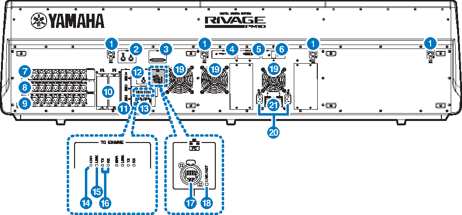
Rear panel of the control surface
CS-R10
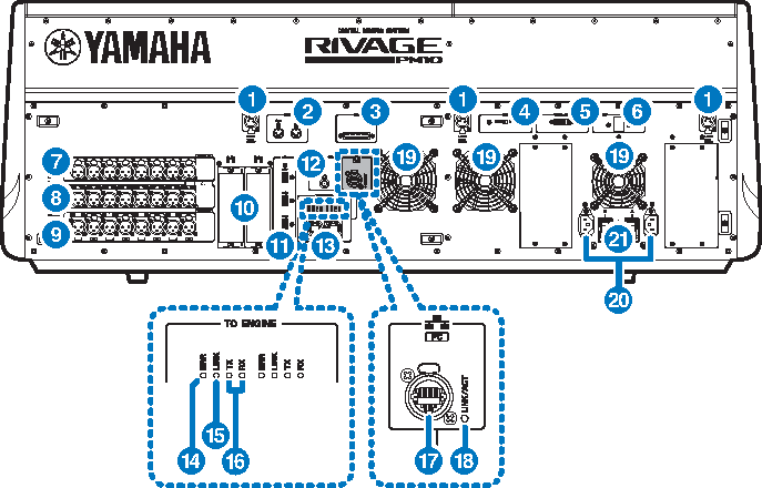
CS-R10-S
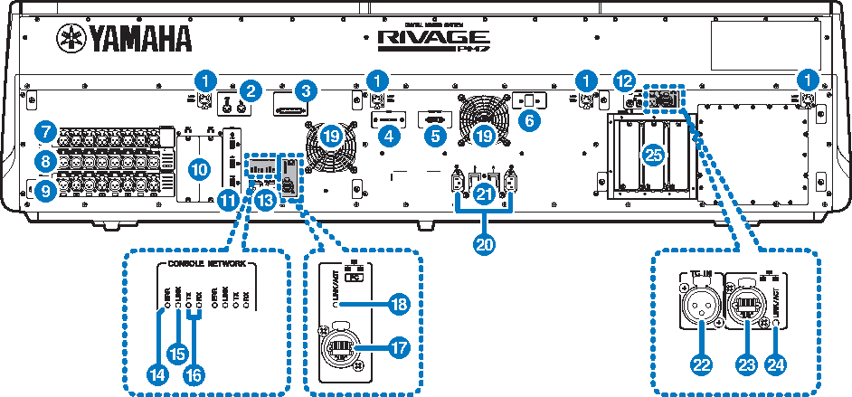
CSD-R7
a | LAMP jacks These 4-pin female XLR output connectors are used to supply power to Yamaha LA1L gooseneck lamps supplied with the unit (CS-R10, CSD-R7: 4 jacks; CS-R10-S: 3 jacks). |
b | MIDI OUT/IN jacks These connectors are used to transmit and receive MIDI messages to/from external MIDI devices. |
c | GPI connector This is a D-sub 25-pin female connector that allows communication (8-in, 8-out) with a GPI-equipped external device. |
d | [FAN] switch Sets the internal cooling fan to operate at either HIGH or LOW speed. NOTE
|
e | VIDEO OUT connector Connect your external display monitor (XGA 1024x768 or higher) to this DVI-D (Dual-link) connector. |
f | [RESET] switch Resets the control surface. Only the controls (screens, indicators, and control keys and knobs) on the control surface will restart without interrupting audio. Use this switch in case the control surface becomes non-responsive to your operations. |
g | OMNI IN jacks These are balanced XLR-3-31 female input jacks for inputting analog audio signals from line level devices or microphones. They feature SILK digital processing. |

h | OMNI OUT jacks These are balanced XLR-3-32 male output jacks that transmit analog audio signals. |

i | AES/EBU jacks Both input and output jacks feature built-in sampling rate converters. IN These are balanced XLR-3-31 female input jacks that accept digital audio signals in AES/EBU format. OUT These are balanced XLR-3-32 male output jacks for outputting digital audio signals in the AES/EBU format. |
j | MY card slots Install optional Mini-YGDAI I/O cards here to expand I/O ports. |
k | USB port Use these ports to connect a USB storage device such as a flash drive, USB mouse, or USB keyboard. |
l | WORD CLOCK OUT connector (CS-R10, CS-R10-S) This BNC connector is used to transmit word clock signal to an external device. WORD CLOCK OUT/IN connectors (CSD-R7) These are BNC connectors used to transmit/receive word clock signals to/from an external device. The WORD CLOCK IN connector is internally terminated by a 75-ohm resistor. |
m | TO ENGINE OUT/IN connectors (CS-R10, CS-R10-S), CONSOLE NETWORK connector (CSD-R7) These RJ-45 connectors allow the unit to be connected to a console network in a ring topology via Ethernet cables (CAT5e or higher recommended). NOTE
|
n | ERR indicators This indicator lights up or flashes red if an error occurs. In such an event, please contact your Yamaha dealer. |
o | LINK indicator This indicator flashes or lights up, depending on the network status. |
Green (flashing) | The unit is preparing to connect to the console network. If it continues flashing, the system is not functioning properly. If the problem persists after you take the following actions, please contact your Yamaha dealer.
|
Green (lit steadily) | The unit is connected to the console network properly. |
p | TX/RX indicators The appropriate indicator flashes green when data is transmitted from (TX) or received at (RX) the TO ENGINE OUT/IN connectors. |
q | NETWORK connector This RJ-45 connector allows the unit to be connected to a computer or network device via an Ethernet cable (CAT5e or higher recommended). NOTE
|
r | LINK/ACT indicator This indicator flashes or lights up green, depending on the connection status. |
s | Vent The control surface is equipped with cooling fans. These vents let warm air out from the unit. Please make sure that you do not block the vents with any object. |
t | AC IN connectors Use these sockets to connect the supplied power cords. First connect the AC power cords to this unit, and then insert the power cord plugs into AC outlets. Insert the cable plugs all the way until they lock in place securely. The supplied AC power cords feature a V-lock mechanism via a latch, which prevents the power cords from disconnecting accidentally.
To disconnect each power cord, remove it while pressing the latch on the plug.
|
 CAUTION
u | I/z(Power switches) Toggle between power on (I) and off (z). While the power is turned on, the “UTILITY section” on the top panel will light up. |
v | TC IN connector This balanced XLR-3-31-type female connector accepts time code signals from a connected external device. |
w | NETWORK connector This RJ-45 connector enables you to connect an external device via an Ethernet cable (CAT5 or higher). NOTE
|
x | LINK/ACT indicator This indicator lights up or flashes green, depending on the connection status. |
y | HY card slots Enable you to install optional HY cards and connect to an I/O rack, such as RPio622, to expand I/O ports. |