Connections
4. Connections
4.1. Audio input connections
![]() WARNING
WARNING
-
Unplug the device from mains before connecting or disconnecting any cable to it.
● For the PC-D series
Connect the rear panel XLR jacks to the balanced outputs of the mixer, and input analog signals. The jack polarity is shown in the illustration below (IEC 60268).

● For the PC-DI series
- When attaching a cable to a Euroblock plug, strip the wire as shown in the illustration, and use stranded wire to make connections. In the case of Euroblock wiring, stranded wire may break more easily due to metal fatigue caused by the weight or vibration of the cable. Use the included cable ties to secure the cables to the tab.

![]() CAUTION
CAUTION
-
When using stranded wire, do not tin the strands with solder.
-
If connections will be frequently plugged and unplugged, as in a portable setup, we recommend that you use rod terminals equipped with insulating sleeves. Use rod terminals whose conductor section is as shown below.
5.08 mm Euroblock 6-pin

External diameter 1.6 mm or less, and length approximately 7 mm
(such as the AI0, 5-6WH made by the Phoenix Contact company)

4.2. Connections using the [GPI IN / OUT] connectors
The GPI connectors on the rear panel can be used as GPI (General Purpose Interface) input/output connectors. These connectors provide six GPI IN ports and four GPI OUT ports. For example you could use an external switch to control parameters inside the PC-D/DI series unit, or cause operations on the PC-D/DI series unit to send control signals to an external device.
The following illustration shows an example of an external circuit that controls GPI via a GPI connector.
The [IN]-1–6 pins detect voltages for a "L" signal (0V) or a "H" signal (5V). The [OUT]-1–4 pins output a "L" signal (0V) or a "H" signal (5V).
| Example: Using a switch to control the PC-D/DI series unit | Example: Illuminating the LED of an external device from the PC-D/DI series unit |
|---|---|
|
|
|


4.2.1. Cable management
-
When attaching a cable to a Euroblock plug, strip the wire as shown in the illustration, and use stranded wire to make connections. In the case of Euroblock wiring, stranded wire may break more easily due to metal fatigue caused by the weight or vibration of the cable. Use the included cable ties to secure the cables to the tab.

![]() CAUTION
CAUTION
-
When using stranded wire, do not tin the strands with solder.
-
If connections will be frequently plugged and unplugged, as in a portable setup, we recommend that you use rod terminals equipped with insulating sleeves. Use rod terminals whose conductor section is as shown below.
External diameter 1.3mm or less, and length approximately 5mm
(such as the AI0, 5-6WH made by the Phoenix Contact company)

4.3. Speaker cable selection
![]() WARNING
WARNING
-
The output jacks of the power amp carry high voltage. When connecting this unit to speakers, you must use cables that at a minimum satisfy the requirements of NEC (National Electrical Code) UL13 CL3 (300V or less).
To minimize power loss or damping factor loss in speaker cables, refer to the following table and use speaker cable of the appropriate gauge.
|
Load impedance (Ohms) |
2 |
2.6 |
4 |
8 |
|
Cable |
Maximum cable length (m) |
|||
|
2.5mm 2 (AWG 13) |
20 |
28 |
40 |
80 |
|
4mm 2 (AWG 11) |
32 |
40 |
64 |
128 |
|
6mm 2 (AWG 9) |
48 |
64 |
96 |
192 |
![]() NOTE
NOTE
-
The Euroblock connectors of the PC-DI series should be used with AWG24 (0.2sq)–AWG8 (8sq) cables.
4.4. Speaker connections
● For the PC-D series
This product uses four Speakon output jacks (NL4) to connect speakers.
NeutrikNL4 plug

The outputs of this product can be bridged in pairs of two channels.
Since there are no dedicated outputs for use in bridge mode, take care to observe the following pin assignments.
| SINGLE | BRIDGE | ||
|---|---|---|---|
|
NL4 A |
1+ |
CH A+ |
CH A+ |
|
1- |
CH A- |
CH A- |
|
|
2+ |
CH B+ |
- |
|
|
2- |
CH B- |
- |
|
|
NL4 B |
1+ |
CH B+ |
- |
|
1- |
CH B- |
- |
|
|
2+ |
CH A+ |
CH A+ |
|
|
2- |
CH A- |
CH A- |
|
|
NL4 C |
1+ |
CH C+ |
CH C+ |
|
1- |
CH C- |
CH C- |
|
|
2+ |
CH D+ |
- |
|
|
2- |
CH D- |
- |
|
|
NL4 D |
1+ |
CH D+ |
- |
|
1- |
CH D- |
- |
|
|
2+ |
CH C+ |
CH C+ |
|
|
2- |
CH C- |
CH C- |
|
![]() WARNING
WARNING
-
Do not touch the pins of unused channels, or allow them to short.
High voltage is present even at unused pins.
● For the PC-DI series
This product uses Euroblock connectors (7.6 mm 8-pin) for speaker connections.
Insert the tip of a screwdriver into the square hold located on the top of the cable insertion opening. Inserting the screwdriver and lifting the internal spring allows the cable to be inserted or removed.

The outputs of this product can be bridged in pairs of two channels.
Since there are no dedicated outputs for use in bridge mode, take care to observe the following pin assignments.
| SINGLE | BRIDGE | ||
|---|---|---|---|
|
EURO A |
+ |
CH A+ |
CH A+ |
|
- |
CH A- |
CH A- |
|
|
EURO B |
+ |
CH B+ |
- |
|
- |
CH B- |
‐ |
|
|
EURO C |
+ |
CH C+ |
CH C+ |
|
- |
CH C- |
CH C- |
|
|
EURO D |
+ |
CH D+ |
- |
|
- |
CH D- |
- |
|
![]() WARNING
WARNING
-
Do not touch the pins of unused channels, or allow them to short.
High voltage is present even at unused pins.
4.5. High impedance connections (PC-DI series only)
The PC-DI series also supports high impedance (100V/70V line).
■ Number of speaker systems that can be driven
As long as the total rated input of the speaker systems used is within the output value of the power amp, any number of speaker systems can be connected in parallel.
When using high-impedance connections, the rated input of the speaker system is determined by the settings of the speaker transformer used with the speaker system.
If using the 600W output PC406-DI with a speaker system whose rated input is 20W due to the attached speaker transformer, calculations * show that we can use up to 30 speaker units per channel, and up to 120 speaker system units for the total of four channels.
A combination of speaker systems with different rated input can also be connected.
* In consideration of impedance variance in the primary side of the transformer, future change in transformer tap, and future addition of speakers, we recommend that you allow a margin of about 20%.

■ High-impedance connection example

4.6. Power supply connection
![]() WARNING
WARNING
-
You must use the included power cord. Do not use the included power cord with any other product. Doing so may cause malfunction, overheating, and fire.
![]() NOTICE
NOTICE
-
Position the power cord so that the rear exhaust does not contact it directly. The temperature of the rear exhaust might cause the power cord to deform.
-
Connect the included power cord.
First connect the power cord to the unit, and then connect the power plug to an electrical outlet.
When connecting the power cord, insert it all the way, and then twist it clockwise until you hear the click. When removing the power cord, pull the latch toward yourself, turn the connector counterclockwise, and remove it.

![]() NOTE
NOTE
-
Turning the unit on and off in rapid succession by connecting and disconnecting the power plug can cause it to malfunction. After turning the unit off by disconnecting the power plug, wait for at least five seconds before reconnecting the power plug to turn the unit on.
4.7. Switching the power between standby/on
To prevent loud noise from being emitted from the speaker when the power is turned on, power-on each unit in the order of audio sources, mixer, and finally the amp. When turning the power off, reverse this order.
■ Standby → power on
-
Hold down the power switch for two seconds or longer.
The power turns on, and the button changes from blinking to lit (green). After a time, the HOME screen (VOLUME) appears.
■ Power on → standby
-
Press the power switch.
The display shows a confirmation message.
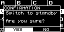
-
Turn the main knob to select "YES," and then press the main knob to confirm; the power switches to standby mode.
![]() NOTE
NOTE
-
The settings at the time the power was turned off (the state when disconnected from the AC outlet) are saved. The next time the power is turned on, the unit starts up with those settings.
![]() NOTICE
NOTICE
-
When this product is connected to an AC outlet, it is in standby mode, and a small amount of current is flowing. If you will not be using this product for an extended period of time, be sure to disconnect the power supply plug from the AC outlet.