SETUP screen
7. SETUP screen
7.1. AMP SETTINGS
Here you can make general settings for the amp.

①
MODE (PC-DI series only)
This specifies whether the connected speaker is Hi-Z (high impedance) or Low-Z (low impedance). High impedance can be selected for 70V systems or 100V systems.
②
HPF (Hi-Z) (PC-DI series only)
This specifies the HPF (high pass filter) that is compulsorily applied for Hi-Z (high impedance). The cutoff frequency can be selected as either 40 Hz or 80 Hz.
③
BRIDGE
This specifies whether adjacent odd-numbered and even-numbered channels will be bridge-connected to operate as a high-power amp. If this is ON, the amp gain is 6 dB higher than when it is OFF.
![]() NOTE
NOTE
-
If bridge-connected, only channel A and channel B of the processing parameters are used.
④
CHANNEL SLEEP
If this is ON, channels that are not being used that day can sleep in order to conserve power and prevent overheating.
⑤
SENS./GAIN (input sensitivity / amp gain)
This specifies the input sensitivity or amp gain.
The input sensitivity can be selected as either 4 dBu or +14 dBu, and the amp gain can be selected as either 26 dB or 32 dB.
| Sensitivity/Gain correspondence table | Sensitivity | Gain |
|---|---|---|
|
PC412
|
+4.0dBu |
(38.0dB) |
|
+14.0dBu |
(28.0dB) |
|
|
(+16.0dBu) |
26.0dB |
|
|
(+10.0dBu) |
32.0dB |
|
|
PC406
|
+4.0dBu |
(35.0dB) |
|
+14.0dBu |
(25.0dB) |
|
|
(+13.0dBu) |
26.0dB |
|
|
(+7.0dBu) |
32.0dB |
![]() NOTE
NOTE
-
For safety, do not input sound while switching this setting. The volume might change significantly.
-
For details on input sensitivity and amp gain, refer to " Input sensitivity and amp gain ."
7.2. CHANNEL NAME

①
Channel name
This sets and shows the channel name. The specified channel name is shown in the lower part of the HOME screen.
Press the main knob to enter character input mode.

In character input mode, turn the main knob to select the location at which you want to input a character, and then press the main knob to confirm. Turn the main knob to select the character that you want to input, and then press the main knob to confirm the character.
If you move the cursor to BS and press the main knob, the last character is deleted.
In character input mode, pressing the [
![]() ] (back) key takes you back to selecting the character position. In this state you can select OK to confirm the title, or select CANCEL to cancel input.
] (back) key takes you back to selecting the character position. In this state you can select OK to confirm the title, or select CANCEL to cancel input.
7.3. AUTO SLEEP
This function conserves power by automatically putting the unit to sleep after the specified time elapses with no input signal.
When an input signal is detected, sleep is automatically defeated.

①
ON/OFF
If this is on, the unit automatically sleeps when there has been no input signal for the specified time.
②
THRESHOLD
This specifies the threshold value in dBFS units at which the presence or absence of an input signal is determined.
③
TIME
This specifies the time from when the input signal ceases until the unit enters sleep mode.
7.4. INPUT REDUNDANCY
The PC-D/DI series has two types of redundancy function as appropriate for the situation: "backup mode" and "override mode."
![]() NOTE
NOTE
-
The INPUT REDUNDANCY function is independent of the Dante network’s redundancy function.
・Backup mode
This automatically switches to a backup circuit if the Dante input audio is interrupted due to a problem such as a malfunctioning input device (BACKUP). Subsequently, if the input audio is restored, the unit can automatically return to the original circuit.
The backup circuit can be specified in two levels.
Dante In (1-4) is the primary (main circuit), Dante In (13-16) is used as Second (2nd SOURCE), and Analog In (1-4) is used as Third (3rd SOURCE). The channel combinations are fixed.
| Primary | 2nd SOURCE | 3rd SOURCE |
|---|---|---|
|
Dante IN 1 |
Dante IN 13 |
Analog IN 1 |
|
Dante IN 2 |
Dante IN 14 |
Analog IN 2 |
|
Dante IN 3 |
Dante IN 15 |
Analog IN 3 |
|
Dante IN 4 |
Dante IN 16 |
Analog IN 4 |
・Override mode
If audio input is detected from Dante input (13–16) jacks or from the analog input jacks, the detected signal will automatically interrupt (OVERRIDE) the audio of the normally-used Dante inputs (1–4). This allows a high-priority emergency broadcast or an in-building announcement to be broadcast as an interrupt.
■ COMMON page

①
MODE (Redundant Mode)
This specifies the redundant function mode.
BACKUP:
The input signal from Dante 1-4 is the primary (main circuit), and when the input from Dante 1-4 is interrupted, the unit automatically switches to the audio from Dante 13-16 or the analog input jacks.
OVERRIDE:
The input signal from Dante 1-4 is the main circuit, and automatic switching occurs only when high-priority audio is detected.
②
AUTO RETURN
For BACKUP mode:
If this is ON, the input source returns to the main circuit when the main circuit recovers.
For OVERRIDE mode:
If this is ON, the input source returns to the main circuit when the audio from Dante 13–16 or the analog input jacks falls below the threshold value.
■ Dante 1–4 page

The backup circuit can be specified in two levels. The channel combinations are fixed.
①
ON/OFF
This specifies for each level whether the backup circuit is enabled (ON) or disabled (OFF).
②
OVR THRESH (OVERRIDE THRESHOLD)
For OVERRIDE mode, this specifies for each channel the input level threshold value at which the presence or absence of an interrupting input signal is determined.
③
OVR RTN DLY (OVERRIDE RETURN DELAY)
For OVERRIDE mode when AUTO RETURN is ON, this specifies the time from when the interrupting signal input ends until the unit switches back to the main circuit.
7.5. LOAD MONITORING
This constantly monitoring the impedance of the connected speaker, and displays an alert message if an abnormal value is shown. You can check the impedance in the LOAD MONITORING page of the HOME screen.
![]() NOTE
NOTE
-
Load monitoring does not operate in the following cases
-
For a high-impedance connection
-
When the amp is in standby mode
-
When the channel is in the Channel Sleep ON or Auto Sleep On state
-

①
ON/OFF
If this is ON, the speaker’s impedance is detected.
②
OSC ON/OFF
If this is ON, an audio signal is output for detection.
![]() NOTE
NOTE
-
Turn this OFF if a signal for detection is being sent from a device (e.g., mixer) connected before this unit.
-
If ① is OFF, a signal for detection is not output even if OSC is ON.
③
OSC LEVEL
This specifies the level of the audio signal for detection.
![]() NOTE
NOTE
-
Gradually raise the OSC LEVEL and check that the impedance value is shown in the HOME screen. However depending on the characteristics of the speaker, there might be cases in which the impedance cannot be detected even if the level is raised to the maximum.
-
If you jumped from the HOME screen’s LOAD MONITORING page directly to this LOAD MONITORING screen, you can move between them at a touch by alternately pressing the [
 ](back) key and the main knob.
④
DETECT. FREQ. (DETECTION FREQ.)
This specifies the frequency of the audio signal for detection.
![]() NOTE
NOTE
-
Adjust the frequency, and check that the impedance value is shown in the HOME screen.
However depending on the characteristics of the connected speaker, there might be cases in which the impedance cannot be detected even if the frequency is changed. Also, if the frequency is lowered too far, it might be heard as an audible sound; in this case, raise the frequency.
⑤
HIGH THRESH (HIGH THRESHOLD)
This specifies the upper limit of impedance that is considered normal.
⑥
LOW THRESH (LOW THRESHOLD)
This specifies the lower limit of impedance that is considered normal.
7.6. POWER SUPPLY

①
PwON DFLT (POWER ON DEFAULT)
When power is applied to the unit, this selects whether the unit starts up in standby mode (STANDBY) or in the same state (POWER ON or STANDBY) as when the power was last disconnected (PREVIOUS).
②
PwON DELAY (POWER ON DELAY)
Specifies the time until the amp’s power supply starts when switching from STANDBY to POWER ON. In cases such as when multiple amps start up simultaneously, you can set this to provide a time lag so that circuit breakers are not tripped.
![]() NOTE
NOTE
-
If the power is switched from the front panel, switching happens immediately, regardless of this setting.
7.7. GPI
7.7.1. About GPI
For details on connection methods and examples of use, refer to "Connections using the [GPI IN / OUT] connectors."
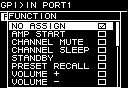
In this screen you can assign functions to the GPI IN (PORT 1–6) and GPI OUT (PORT 1–4).
The following functions can be assigned.
GPI IN
| FUNCTION | Content |
|---|---|
|
NO ASSIGN |
- |
|
AMP START |
Start the amp |
|
CHANNEL MUTE |
Turn mute on/off for the specified channel |
|
CHANNEL SLEEP |
Sleep the amp of the specified channel |
|
STANDBY |
Switch between ON/Standby |
|
PRESET RECALL |
Recall the preset of the specified number |
|
VOLUME + |
Raise the volume 1 dB at a time |
|
VOLUME - |
Lower the volume 1 dB at a time |
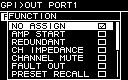
GPI OUT
| FUNCTION | Content |
|---|---|
|
NO ASSIGN |
- |
|
AMP START |
The amp is running |
|
REDUNDANT |
Output when the Input Source status of one of the channels is other than primary |
|
CH IMPEDANCE |
Output when the detected impedance of all specified channels is normal (within the specified upper/lower range) |
|
CHANNEL MUTE |
One of the specified channels is muted |
|
FAULT OUT |
One of the specified channels is in the Fault state |
|
PRESET RECALL |
The preset of the specified number is recalled |