
Names and functions of each part
2. Names and functions of each part
2.1. Front panel
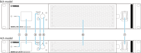
①
[POWER] indicator
This indicator displays the power supply status.
|
|
Green |
Steady light |
Power-on state |
|
|
Green |
Flashing |
Sleep state (Power-saving mode) |
|
|
No light |
Power-off state |


Sleep is a power-saving mode in which no power is supplied to the amplifier unit. You can switch between the power-on state and the sleep state through screen operation, ProVisionaire Design or the [REMOTE] connector on the back.
②
Color display
It displays the setting status of various functions and other items. You can graphically fine-tune EQ, delay, routing, and more. The display has a backlight, and you can adjust the brightness and set the display to automatically light off (
AUTO-DIMMER
).
③
[MENU/HOME] button
Press this button to switch the display (②) between the MENU screen and the HOME screen.
④
[
 ] (Back) button
Press this button to return the display (②) to the previous screen. Press and hold it for more than one second to return to the HOME screen.
⑤
Main knob
Turn this knob to move the cursor or change parameter values, and press it to confirm. You can also adjust the values in finer increments by holding down it while turning.
 NOTE
NOTE
When the front panel operations are locked, you cannot adjust the settings. Unlocking the panel before operating the panel.
⑥
Air inlet
This product is equipped with a cooling fan that takes in air from the front and exhausts it from the rear. Air is drawn in from this air inlet, so do not block the inlet with any obstacles.
 NOTICE
If the air inlet becomes clogged with dust, the device temperature may increase, potentially shutting it down. Clean this port regularly.
⑦
Power switch
Use this switch to turn the power of this device on and off.

You can also start the device in the state (on or sleep) when the power was last turned off ( POWER ON DEFAULT ).
 WARNING
To avoid loud noise from the speakers, turn on the power in the following order: audio source, mixer or processor, and then amplifier. When turning off the power, turn it off in the reverse order.
NOTICE
-
Rapidly turning the power switch on and off in succession may cause faulty operation. After turning the power switch off, wait at least five seconds before turning it on again.
-
If you change any parameters, do not turn off the power switch for three seconds after making the changes. If you turn it off within three seconds, the parameters may not be saved.
-
If this product will not be used for an extended period of time, turn off the power switch.
2.2. Rear panel
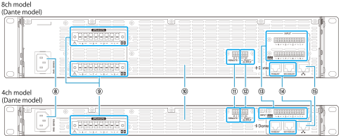
⑧
[AC IN] socket
Connect the included power cord in the following order.
 CAUTION
Turn off the power before you connect or disconnect the power cord.
-
Connect the power cord plug to the AC IN connector.
-
Connect the plug on the other end of the power cord to an AC outlet.
NOTE
When disconnecting the power cord, perform the steps in reverse.
WARNING
-
This product is designed to be connected to earth ground. To prevent electric shock and damage to the device, use the power cord included with the product to ensure a reliable earth ground connection. If you are unsure how to connect, contact the repair support center listed at the end of this manual.
-
Be sure to use the power cord included with the product. Using any other power cord may result in overheating or electric shock.
⑨
[SPEAKERS] connectors (Euroblock)
These Euroblock connectors are used to connect speakers. The 4-channel model has 8 pins, and the 8-channel model has 16 pins. Use the included 8-pin Euroblock plug.
Connecting to the [SPEAKERS] connector
WARNING
Do not touch or short the pins on unused channels. High voltage is applied even to unused pins.
⑩
Exhaust outlet
This product is equipped with a cooling fan. Air is emitted from this exhaust outlet, so do not block the outlet with any obstacles.
⑪
[REMOTE] connector (6-pin Euroblock connector on the left side)
This is a 3-pin Euroblock connector for externally controlling the mute-on/off of all channels and the sleep/power-on of the device.
For external control: [REMOTE] connector and [FAULT OUTPUT] connector
⑫
[FAULT OUTPUT] connector (6-pin Euroblock connector on the right side)
This is a 3-pin Euroblock connector used to control an external device when a fatal fault occurs in the device. When the amplifier is operating normally, NC and C are shorted. When an abnormality occurs, NO and C are shorted. If a fault occurs, the alert indicator [AL] on the HOME screen will light up red.
For external control: [REMOTE] connector and [FAULT OUTPUT] connector
⑬
[INPUT] terminal (Euroblock)
This is a Euroblock connector for analog audio input. The 4-channel model has 12 pins, and the 8-channel model has 24 pins. Each channel consists of the following three pins: hot, cold, and ground.
Connecting to the [INPUT] connector
⑭
Dante connectors [PRIMARY] and [SECONDARY] (Dante models only)
These are 1000BASE-T compatible Ethernet connectors for connecting this product to Dante devices using an Ethernet cable.
NOTE
-
Connect only Dante devices or Gigabit Ethernet-compatible devices (including computers).
-
Yamaha’s Dante-compatible devices have a built-in network switch, so the hop count is two or more. Therefore, the LATENCY setting of 0.15 msec is grayed out and cannot be selected in Dante Controller.
⑮
NETWORK connector
This is an Ethernet connector for connecting this product to a computer using an Ethernet cable.
It is primarily used to monitor and control multiple connected devices from
"Software used"
.