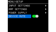
SETUP screen
5. SETUP screen
Configure the input settings, amplifier mode, and power supply settings.
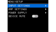
5.1. INPUT SETTINGS
Configure the input settings.
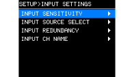
5.1.1. INPUT SENSITIVITY
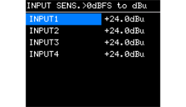
Set the analog input sensitivity and Dante input sensitivity for each channel. The sensitivity can be set in 0.5 dBu increments.
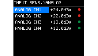
Correct the volume difference when switching from Dante to analog input using the redundant function.
For the analog output of each connected device, please refer to the respective instruction manual.
5.1.2. INPUT SOURCE SELECT
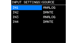
Set whether to enable analog input (ANALOG) or digital input (Dante) for each channel.
5.1.3. INPUT REDUNDANCY
The XMS series has two types of redundancy functions: “backup mode” and “override mode” that can be used according to the situation.
 NOTE
NOTE
INPUT REDUNDANCY is a function independent of the Dante network redundancy function.
-
Backup mode
If the Dante input audio is interrupted due to a problem such as an input device failure, the system will automatically switch to the backup line (BACKUP). After this switching, if the input audio returns, the original line will be automatically restored.Dante In (1-8)/(1-4) is used as the main line, and Analog In (1-8)/(1-4) is used as the backup line. The channel combinations are fixed.
Main line Backup line Dante IN 1
Analog IN 1
Dante IN 2
Analog IN 2
Dante IN 3
Analog IN 3
Dante IN 4
Analog IN 4
Dante IN 5
Analog IN 5
Dante IN 6
Analog IN 6
Dante IN 7
Analog IN 7
Dante IN 8
Analog IN 8
-
Override Mode
When audio input from an analog input connector is detected, the detected signals will automatically interrupt (OVERRIDE) the audio from the Dante inputs (1-8)/(1-4), which is normally used. This mode allows for interrupt broadcasts such as high-priority emergency broadcasts and in-house announcements.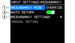
① REDUNDANCY MODE
Set the mode of the redundancy function.
BACKUP : The input signals from Dante (1-8)/(1-4) are handled as the primary (main line). If the input from Dante (1-8)/(1-4) is interrupted, the system automatically switches to the audio from the analog input connector.
OVERRIDE : The input signals from Dante (1-8)/(1-4) are handled as the main line, and the system automatically switches only when a higher-priority audio signal is detected.② AUTO RETURN
In BACKUP mode:
When this item is set to ON, the input source will return to the main line when the main line is restored.
In OVERRIDE mode:
When this item is set to ON, the input source will return to the main line when the audio from the analog input connector remains below the threshold value for the set time or longer.③ REDUNDANCY SETTINGS
You can set the redundancy function for each channel. The channel number is displayed in the upper right corner of the screen, and you can select the channel with the main knob.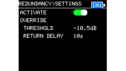
ACTIVATE REDUNDANCY
Set whether to enable (ON) or disable (OFF) the backup line for each level.OVERRIDE THRESHOLD
In override mode , set the input level threshold value for each channel, which determines whether or not an interrupt input signal exists.OVERRIDE RETURN DELAY
When AUTO RETURN is set to ON in override mode , set the time from when the input of the interrupt input signals is stopped until the input source switches back to the main line.④ MANUAL RETURN
This function is available when AUTO RETURN (②) is set to OFF. In BACKUP mode, you can manually return to the main line when the main line is restored. In OVERRIDE mode, you can manually return to the main line when the conditions for returning to the main line are met.
5.1.4. CHANNEL NAME
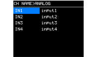
Set the channel name for the analog input. The channel name you set will be displayed in ProVisionaire Design.
Press the main knob to enter the character input mode.
How to enter characters
5.2. AMP SETTINGS
Configure the general settings for the amplifier and power sharing settings.
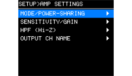
5.2.1. MODE/POWER-SHARING
Set the amplifier mode and power sharing according to the impedance of the connected speakers and the system configuration.
Settings are configured by four-channel group. Select channel 1-4 or 5-8 and press the knob to display the setting screen.
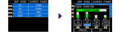
● Setting the amplifier mode
Select from 4 Ω, 8 Ω, 70 V, or 100 V according to the impedance of the speaker to be connected.
When the setting is done, select [OK] and press the main knob to confirm.
For low impedance connection
When connecting a speaker with an impedance of 8 Ω or more, set 8 Ω. When connecting a speaker with an impedance of 4 Ω or more and less than 8 Ω, set 4 Ω.
For high impedance connection
Configure the setting to match the specifications of the equipment to be installed (70 V or 100 V).
NOTE
When you set up a high-impedance connection, the HPF is automatically enabled.
● Setting up power sharing
By freely allocating the maximum output value to each channel, you can build a system with minimal excess power.
-
Set the power required for each channel.
Make sure the total output power of the four channels does not exceed the upper limit. If the upper limit is exceeded, “TOTAL” will turn red.

XMS24s8, XMS24s8-D, XMS12s4, and XMS12s4-D units
Mode Voltage condition Resistance condition Maximum output (per channel) SE/BTL Total output power of four channels 8 Ω
-
8 Ω
600 W
≦ 300 W: SE
300 W <: BTL (*)4ch model :
Total of CH1 to 4 ≦ 1200 W
8ch model :
Total of CH1 to 4 ≦ 1200 W
Total of CH5 to 8 ≦ 1200 W4 Ω
4 Ω
600 W
SE
100 V
100 V
33.3 Ω
300 W
BTL
70 V
70 V
16.6 Ω
300 W
BTL
XMS12s8, XMS12s8-D, XMS06s4, and XMS06s4-D
Mode Voltage condition Resistance condition Maximum output (per channel) SE/BTL Total output power of four channels 8 Ω
–
8 Ω
300 W
≦ 150 W: SE
150 W <: BTL (*)4ch model :
Total of CH1 to 4 ≦ 600 W
8ch model :
Total of CH1 to 4 ≦ 600 W
Total of CH5 to 8 ≦ 600 W4 Ω
4 Ω
300 W
SE
100 V
100 V
66.6 Ω
150 W
BTL
70 V
70 V
33.3 Ω
150 W
BTL
The maximum convergence value of each amplifier output is one-eighth (W) of the table above.
*If you set the output to exceed 300 W at 8 Ω, the connection will automatically switch to BTL . Note that the S/N ratio may decrease when the connection switches to BTL. -
When the setting is done, select [OK] and press the main knob to confirm.
If the setting value for the power exceeds the upper limit, [OK] cannot be selected. Adjust the setting so that the total remains within the limit.
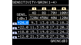
5.2.2. SENSITIVITY/GAIN
This screen lists input sensitivity settings configured in INPUT SENSITIVITY and amplifier gains based on the settings. Changing the sensitivity will also change the GAIN value.The amplifier gains are only displayed and cannot be set.
5.2.3. HPF(Hi-Z)
Set the high-pass filters that are applied in a high-impedance connection. When you select the impedance (70V/100V) in AMP MODE, the HPF is automatically set.
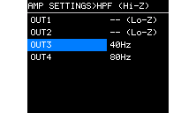
If you set the filter to 40 Hz, make sure that the speaker transformer you are using has sufficient low-frequency characteristics.
 NOTICE
Note that if low frequencies are input to a power amplifier, magnetic saturation of the speaker transformer may occur, damaging the speaker, speaker transformer, and amplifier.
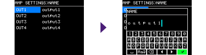
5.2.4. OUTPUT CH NAME
Set the output channel name. The channel name you set will be displayed in ProVisionaire Design.
How to enter characters
5.3. POWER SUPPLY
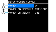
Set the power state when the power switch is turned on.
①
POWER
Switch between power-on (ON) and sleep (SLEEP) modes.
②
POWER ON DEFAULT
Select whether to start the unit always in the power-on state (ALWAYS ON) when the power switch is turned on, or to start the unit in the same state as the unit was last turned off (power-on or sleep) (PREVIOUS).
③
POWER ON DELAY
Set the time required for the amplifier to start up when this product is powered on. To simultaneously start multiple amplifiers, set their time with a time stagger to avoid a strain on the breaker.