
How to operate
4. How to operate
4.1. Front panel operations
The HOME screen/MENU screen will be displayed on the front panel display. You can check the settings and status of this product.
|
|
①
Display
|

4.1.1. Basic operations
-
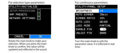
Turn the main knob ③ to select an item.
The selected item will be highlighted in blue and black on the display.
If ▶ is displayed on the right, there is a lower level.
-
Press the main knob to confirm the selection.

-
Repeat steps 1 and 2 to move to the desired parameter editing screen.
-
Edit the parameters.
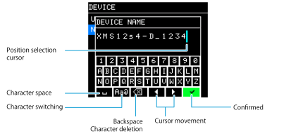
4.1.2. How to enter characters
-
Turn the main knob to select [◀] or [▶] to move the cursor.
-
Press the main knob to use the cursor to select the position to enter characters.
-
Turn the main knob to select the character you want to enter, and press the main knob to confirm the character.
Turn the main knob to select the [ ] (backspace) and press the main knob to erase the character to the left of the cursor position.
-
Turn the main knob to select [✓] and press the main knob to confirm.
 NOTE
NOTE
While entering text, press the [
 ] (Back) button to move to [✓].
4.1.3. Switching channels
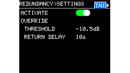
If multiple channels have the same parameter, the channel number is displayed in the top right corner of the screen.
Switch the channel number and set multiple channels.
-
Move the cursor to the channel number and press the main knob.
-
Turn the main knob to select a channel and press the main knob to confirm.
4.1.4. Alert messages
If an abnormality occurs in this product, an alert message will appear on the display.
For details on each message, refer to “Message list” in the references.
Example)
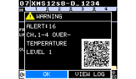
Select [OK] to return to the original screen.
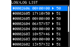
Scan the QR code with your smartphone or tablet to view a detailed description of the alert.Select [VIEW LOG] to display “LOG LIST.”
4.2. HOME screen
This screen is displayed when you turn on the power switch. Important parameters are displayed for each basic function.
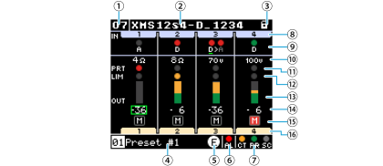
The image shows an 8-channel Dante model.
4.2.1. Main unit settings
①
UNIT ID
Set an ID that allows you to identify the individual XMS series units on the network. If the same models are present in one network, make sure that the IDs do not overlap.
Place the cursor and press the main knob to go to the
DEVICE
screen where you can set the UNIT ID.
②
DEVICE NAME
The device name of this product is displayed. By giving a descriptive name, the device will be more easily identified in ProVisionaire Design.
Place the cursor and press the main knob to go to the
DEVICE
screen where you can set the device name.
③
PANEL LOCK
When the panel is locked, a (lock) symbol is displayed.

④
AMP PRESET
The number and title of the recalled amp preset are displayed. Place the cursor and press the main knob to go to the AMP PRESET screen.
⑤
EDIT
If any parameter is changed after an amplifier preset is recalled or initialized, the
 symbol will light up.
⑥
ALERT indicator
This indicator lights up when an abnormality occurs in the device. Its color changes depending on the importance of the alert.
FAULT: Red
ERROR: Orange
WARNING: Yellow
Normal: Gray
⑦
LINK indicator (Connection status)
This indicator lights up gray if no connection is established, orange if the capacity is 100 Mbps or less, and green if the capacity is 1 Gbps or more. The lines connecting each port show the network configuration.
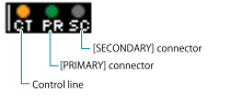
| 2nd Port | Control | Display |
|---|---|---|
|
Redundant |
Separated |
|
|
Merged |
|
|
|
Daisy Chain |
Separated |
|
|
Merged |
|


4.2.2. Channel-specific settings
⑧
INPUT CHANNEL
Unused channels will be grayed out.
⑨
INPUT SOURCE(Redundant) & SIGNAL
The indicator for the selected input signal is displayed.
Move the cursor to the indicator and press the main knob to display the INPUT SENSITIVITY screen, where you can set the input sensitivity.
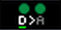
A
............. Analog
D
............. Dante
D>A
………. Redundant connection
The selected line will be underlined.
⑩
AMP MODE
Amplifier output mode
⑪
PROTECT indicator
This indicator lights up red when the protection circuit is activated to mute the channel.

⑫
LIMIT indicator
When the limiter is activated, the speaker output is attenuated and the indicator lights up orange.

⑬
OUTPUT METER
Output signal level
⑭
VOLUME (dB)
Move the cursor to select a channel, and turn the main knob to change the value.
⑮
MUTE
When the channel is muted, the indicator lights up red.

Place the cursor and simultaneously press the main knob and [
] (back) button to switch between mute and unmute.
⑯
OUTPUT CHANNEL
Output channel
4.3. MENU screen
This screen lists the setting items. This screen appears when you press the [MENU/HOME] button on the HOME screen.
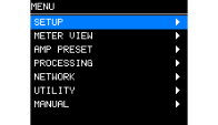
The MENU screen has the following screens: