
NETWORK screen
9. NETWORK screen
Configure network audio (Dante) and remote control settings, and view the network status.
9.1. DEVICE
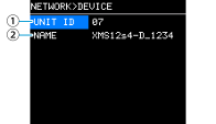
①
UNIT ID
Set an ID that allows you to identify the individual XMS series units on the network.
The set UNIT ID will become effective after this product is restarted. If the same models are present in one network, make sure that the IDs do not overlap.
 NOTE
NOTE
The setting range is from 01 to FE (hexadecimal).
Turn the main knob to select the character you want to enter, and press the main knob to confirm the character. Select YES on the restart confirmation screen. The ID will take effect after the restart.
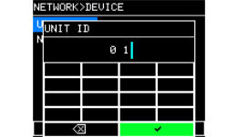
The set UNIT ID will be displayed on the HOME screen.
②
NAME
Set the device name for this product. By giving a descriptive name, the device will be more easily identified in ProVisionaire Design.
How to enter characters
NOTE
-
You can enter a name up to 32 characters long.
-
The characters you can enter are as follows:
ABCDEFGHIJKLMNOPQRSTUVWXYZ
abcdefghijklmnopqrstuvwxyz
0123456789
! “ # $ % & ‘ ( ) * + , - . / : ; < = > ? @ [ \ ] ^ _ ` { | } ~ (space) -
Other characters entered in ProVisionaire Design will be displayed as a question mark (?).
9.2. Dante
Configure the Dante network settings. You can check the status of your Dante network here.
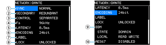
①
SYNC
This indicates "NORMAL" if the network is operating normally, or "NOT READY" if the Dante module is being prepared. Otherwise, the ID of the SYNC message is shown.
②
SECONDARY (SECONDARY PORT)
Select whether to use the two Dante connectors in a redundant connection (REDUNDANT) or a daisy chain connection (DAISY CHAIN).
③
CONTROL
Select whether to mix or separate the control lines
*
and the Dante lines.
-
MERGED : Mixes Dante lines and control lines.
-
SEPARATED : Separates the Dante lines and the control lines.
*Control line: Lines to be remotely controlled by ProVisionaire Design and other means
④
Fs (Dante Fs)
Set the sampling frequency for Dante input and output. Select from 44.1 kHz, 48 kHz, 88.2 kHz, or 96 kHz.
NOTE
Set the frequency to match the Fs of the device for which to patch the audio. If the Fs differs between devices, the audio cannot be patched.
Also, if you change the Fs while the audio is patched, the audio will be cut off.
⑤
LATENCY
Set the latency (Dante latency) of signals sent and received on the Dante network. Select from 0.25 ms, 0.5 ms, 1 ms, 2 ms, and 5 ms.
The appropriate latency setting for signals sent and received on a Dante audio network varies depending on the connection method and scale. This section explains how to set latency based on the connection status of Dante-compatible devices connected to the XMS series.
■ Relationship between switches and hop count
The latency setting for a Dante audio network depends on the hop count in the network.
The hop count represents the number of switches between the leader device and the farthest connected device in series. In addition to switching hubs, switches are also built into the XMS series and I/O devices. This hop count gives you an idea of the latency you should set.
The guideline for general latency settings based on the hop count is as follows:
| Hop count | Latency (ms) |
|---|---|
|
Up to 3 |
0.25 |
|
Up to 5 |
0.5 |
|
Up to 10 |
1.0 |
|
Up to 20 |
2.0 |
|
21 or more (or when a problem occurs) |
5.0 |
NOTE
-
If the latency settings of both patched devices are different, the slower setting takes effect.
-
Depending on the network conditions, you may need to set a higher latency even with a smaller hop count.
-
If any problem occurs, try selecting 5.0 ms to isolate whether the latency settings are the cause.
⑥ ENCODING (Display only)
⑦
LABEL
Displays the Dante device label.
⑧
LOCK
Displays the status of the Dante Device Lock. You can set the status using Dante Controller.
When the lock is set, LOCKED is displayed. When the lock is released, UNLOCKED is displayed. When the lock is set, you cannot change the Dante settings.
⑨
DDM (Dante Domain Manager)
If a DDM server is present on the network or if the device is joined to a domain, the status is displayed.
-
STATE : Displays the domain joining status.
DOMAIN Joined to a domain
DISCONNECTED Joined to a domain but not connected to the DDM server
UNMANAGED Not joined to a domain -
LOCAL : Displays the access status in the Dante settings (including Dante PATCH) of the product you are currently operating.
READ WRITE Can be changed
READ ONLY Cannot be changed
⑩
AES67
Displays the setting status of the AES67 mode (ENABLE/DISABLE).
9.3. CONTROL
Configure the remote control settings.
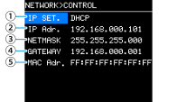
①
IP SET. (IP SETTINGS)
Select the method for setting the IP address.
-
UNIT ID : Sets 192.168.0.### (### = UNIT ID).
-
DHCP : Sets the IP address assigned by the DHCP server. The IP address, NETMASK, and GATEWAY will be obtained automatically. If no DHCP server is present on the network, the device will operate with a link local address (169.254.xxx.xxx).
-
STATIC IP : Manually set the IP address gateway.
②
IP ADR.
Displays the IP address. If you selected STATIC IP in IP SET., set the IP address here.
③
NETMASK
Displays the subnet mask. If you selected STATIC IP in IP SET., set the subnet mask here.
④
GATEWAY
Displays the default gateway.
Depending on the setting in IP SET. (①), the default gateway will be displayed as follows:
•
UNIT ID
: Default gateway disabled
•
STATIC IP
: Default gateway you manually set
⑤
MAC
Displays the MAC address. This address can only be displayed, but cannot be changed.
NOTE
For the settings for the connectors for remote control communication, refer to “NETWORK screen” - Dante .