
Installation flow
3. Installation flow
Install the product in accordance with the flow as described below.
3.1. Installation
3.2. Connection
3.3. Turning on the power
3.4. Setup
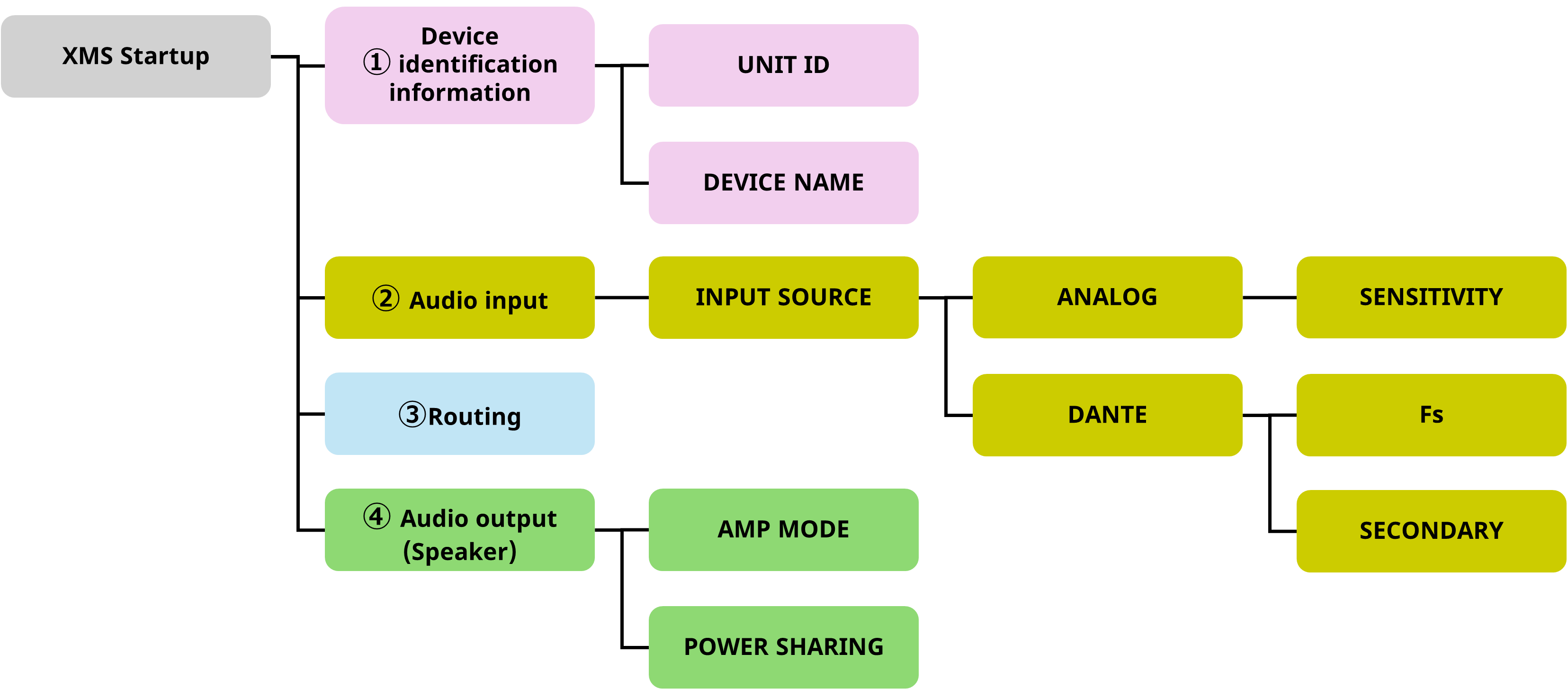
3.5. Checking the wiring
3.1. Installation
Mount the XMS device in a rack.
3.1.1. Precautions for rack mounting
The range of guaranteed operating room temperatures for this product is 0 to 40°C. If the temperature inside the rack becomes elevated, it could negatively affect performance of this product. Be sure to secure adequate ventilation and mount the product in a manner that prevents heat from building up inside the product.
-
Position the rack (in which this product is mounted) at least 10 cm away from any wall or ceiling, and leave the back side open. If the back side of the rack cannot be left open, use a commercially available fan kit or other forced air ventilation system.
*If a fan kit is installed, note that enclosing the back side of the rack can improve heat dissipation in some cases. For more information, refer to the rack and fan kit owner’s manual. -
This product is designed to intake air via the front and discharge it from the rear. Do not install this product along with other devices that intake air from the rear and exhaust it via the front.
-
If this product is mounted together with a third-party power amplifier or other devices that tend to generate heat (excluding the DME5 and DME3 units), leave at least one unit of space between this product and the other devices. To ensure adequate ventilation, install a vented panel in those spaces, or leave the space open.
-
If you are mounting this product along with DME5 and DME3 signal processors in a standard EIA rack, you can mount and operate multiple units without leaving space between units.
-
If you are mounting the product in a rack other than those of the EIA standard, or if you do not use any rack, ensure the following space around the product.
-
4-channel model: At least 10 cm above, 10 cm behind, and 5 cm on both sides
-
8-channel model: At least 10 cm above and 10 cm behind
-
3.2. Connection
3.2.1. Connecting to the [INPUT] connector

Connect the analog output of a mixer or other device to the [INPUT] connector.
For connection, be sure to use the included Euroblock plug with tabs (3.5 mm pitch, 3 pins).
Items to use
-
3-pin Euroblock plug (included)
-
Cable tie (included)
-
Flathead screwdriver
-
Cable to be connected (Handle the cable as follows.)
Cable handling
|
|
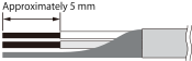
When connecting a cable to a Euroblock plug, strip the cable as shown in the illustration.
|
|
|
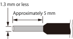
If you use portable equipment and frequently plug and unplug cables, we recommend using a rod terminal with an insulating sleeve or a ferrule terminal. Use the rod terminal whose conductor part has an outer diameter of 1.3 mm or less and a length of approximately 5 mm (such as AI 0,5 - 6 WH manufactured by Phoenix Contact). |
 CAUTION
-
If you use stranded wire, do not solder the wire.
Connection procedure
-
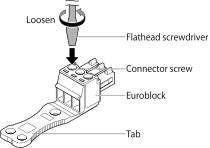
Loosen the connector screws.
-
Insert the cable.

-
Tighten the connector screws securely.
Pull the cable to make sure that it cannot be pulled out accidentally. -
Use the included cable tie to secure the cable to the tab.
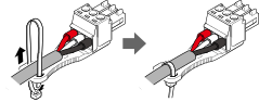
-
Attach the Euroblock plugs to the [INPUT] connectors on the unit.
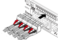
If connecting an unbalanced cable to the [INPUT] connector, connect the “−” and “G” of the Euroblock plug with a wire, such as a jumper wire.

3.2.2. Connecting to the [SPEAKERS] connector

Connect a speaker using a Euroblock connector (7.62 mm pitch, 8 pins).
For connection, be sure to use the included Euroblock plug.
Items to use
-
8-pin Euroblock plug (included)
-
Screwdriver
-
Cable to be connected
Connection procedure
|
Insert the tip of a screwdriver into the square hold located on the top of the cable insertion opening. Inserting the screwdriver and lifting the internal spring allows the cable to be inserted or removed. |
|
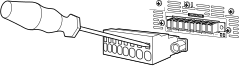
 WARNING
Do not touch or short the pins on unused channels. High voltage is applied even to unused pins.
Connecting speakers
This product is compatible with both high impedance (100 V/70 V line) and low impedance (4 Ω/8 Ω).
|
High-impedance connection |
Low-impedance connection |
|
|
|
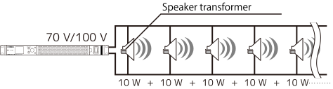
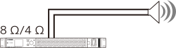
High-impedance connection
■ Number of speaker systems that can be driven
You can connect any number of speaker systems in parallel as long as the total rated input value of the speaker systems used is within the output value of the power amplifier.
For high-impedance connections, the rated input of the speaker systems is determined by the speaker system and the speaker transformer settings used.
When you use the XMS12s4-D unit with the output of 1200 W with a speaker system whose rated input is set to 20 W by installing a speaker transformer, if power is evenly distributed to each channel, theoretically (*) up to 15 speaker systems can be connected per channel, and up to 60 speaker systems in total across all four channels.
You can also connect speaker systems with different rated inputs together.
(*) We recommend that you leave a margin of about 20% to allow for deviations in the transformer’s primary impedance, future changes in the transformer tap, and the addition of speakers.
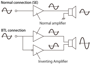
SE (SINGLE END) and BTL (Balanced Transformer Less) connections
If AMP MODE is set to 8 Ω and the power is set to more than 300 W, the connection will automatically switch to BTL. When the BTL connection is used, the output will be doubled because two amplifier channels are used as one amplifier channel. When the connection is switched to BTL, an icon will appear on the screen.
 NOTICE
Note that the amplifier output is connected to each of the positive and negative terminals, so contact with other terminals or the chassis may cause malfunction.
3.2.3. Establishing the network connection

Use an Ethernet cable to connect the [NETWORK] connector to the computer on which ProVisionaire Design is installed. It is primarily used to monitor and control multiple connected devices from ProVisionaire Design.
For Dante models, the CONTROL (MERGED/SEPARATED) setting allows for flexible design suitable for the audio system, such as sharing or distributing functions with the Dante connectors.
NOTICE
To prevent electromagnetic interference, use a CAT5e or higher STP cable (shielded twisted pair cable) for the cable to be connected to the NETWORK connector.
IP address settings
To monitor and control this product from ProVisionaire Design, set the control IP address and the IP address of your computer.
We recommend setting IP SETTINGS to DHCP to obtain the IP addresses automatically (if there is no DHCP server, a link-local address will be assigned).
For details, refer to the New CIS Ecosystem Setup Guide (Network Edition).
3.2.4. For Dante models: Dante connection

Use an Ethernet cable to connect the Dante [PRIMARY]/[SECONDARY] connector to the Dante device.
NOTICE
To prevent electromagnetic interference, use a CAT5e or higher STP cable (shielded twisted pair cable) for the cable to be connected to the network connector.
■ Overview of Dante
The Dante models use Dante as the protocol for transmitting audio signals. Dante is a protocol developed by Audinate. In a Gigabit Ethernet-compatible network environment, this protocol has the advantage of being able to simultaneously handle multiple audio signals with different sampling frequencies/bit rates, as well as device control signals.
-
For details on Dante, refer to the Audinate website.
http://www.audinate.com/ -
Additionally, the Yamaha Pro Audio website also provides a variety of information about Dante.
http://www.yamahaproaudio.com/
NOTICE
Do not use the EEE function (*) of network switches in a Dante network.
The EEE function may cause poor clock synchronization performance, resulting in audio interruptions.
Therefore, we strongly recommend that you:
-
Turn off the EEE function on all ports used for Dante traffic if you use managed switches. Do not use a switch that does not allow you to turn off the EEE function.
-
Do not to use a switch that supports the EEE function if you use unmanaged switches. These switches cannot turn off the EEE function.
* EEE (Energy Efficient Ethernet) function: A technology that reduces the power consumption of Ethernet devices when network traffic is low. This technology is also known as Green Ethernet or IEEE802.3az.
 NOTE
NOTE
-
When the XMS series Dante models are used in combination with Yamaha network switches, the switch settings optimized for Dante are configured automatically.
Settings include QoS, IGMP snooping, flow control disable, and EEE disable. For details on these settings, refer to the following.
https://www.yamaha.com/2/how-to-choose-a-network-switch/
● About connection methods
For connecting the Dante model to the Dante network, there are two methods: redundant connection and daisy chain connection. You can use these methods in combination. In addition to the CONTROL line setting (MERGED/SEPARATED), you can select from four types of network systems.
Redundant connection
The redundant connection creates an environment that is more resistant to network failures than the daisy chain network. The redundant connection is a connection method consisting of two lines: a main line (primary) and a sub-line (secondary). Normally, communication is performed over the primary line. However, if a problem such as a disconnection occurs on the primary line, communication will automatically switch to the secondary line.
■ When Control is set to Separated
NOTICE
Keep the number of connected Dante devices to less than 80 on the same network. When connecting 80 or more devices, separate the subnets.
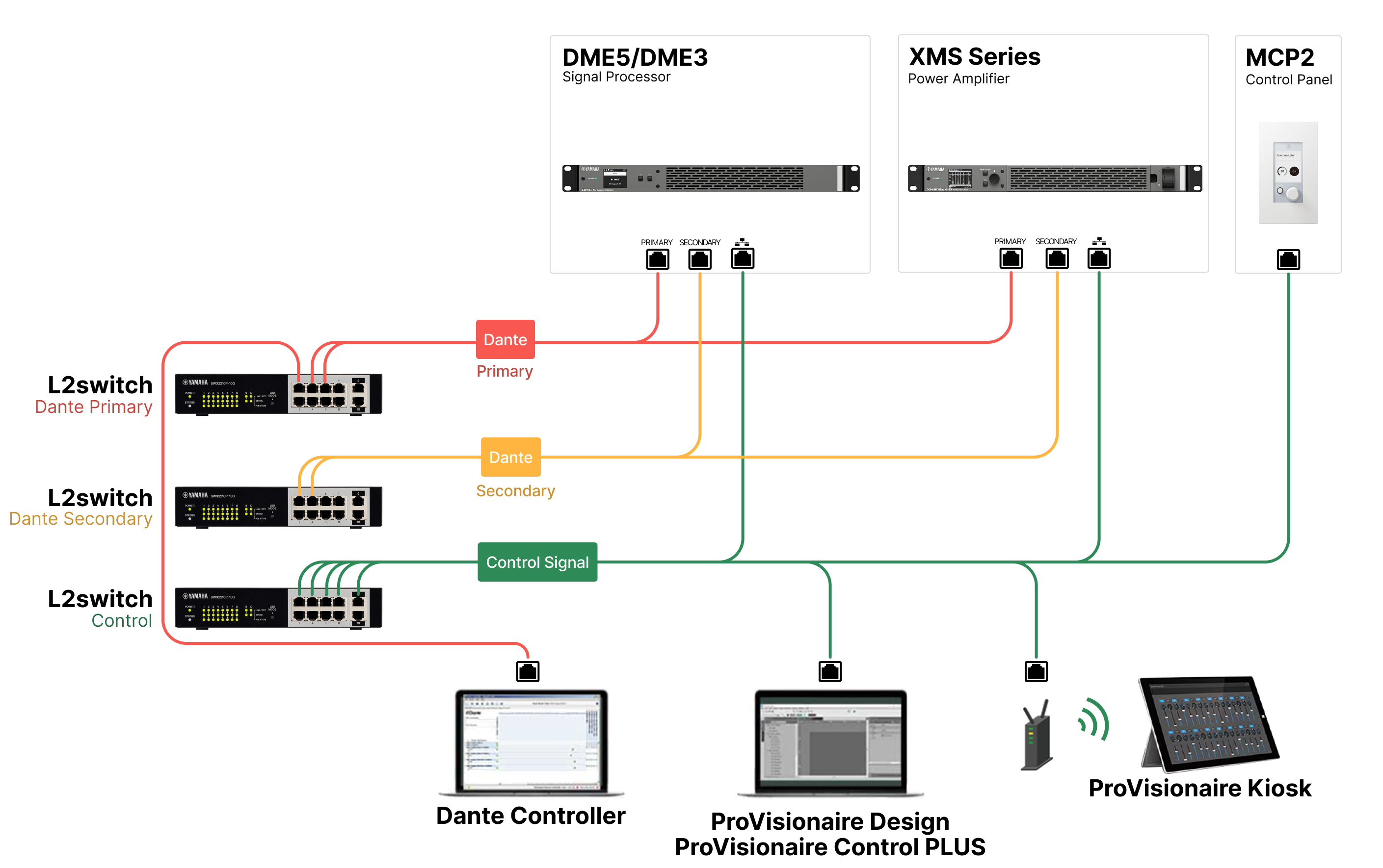
NOTICE
If you run Dante Controller and ProVisionaire Design on the same computer, use separate network interface cards for connection.
■ When Control is set to Merged
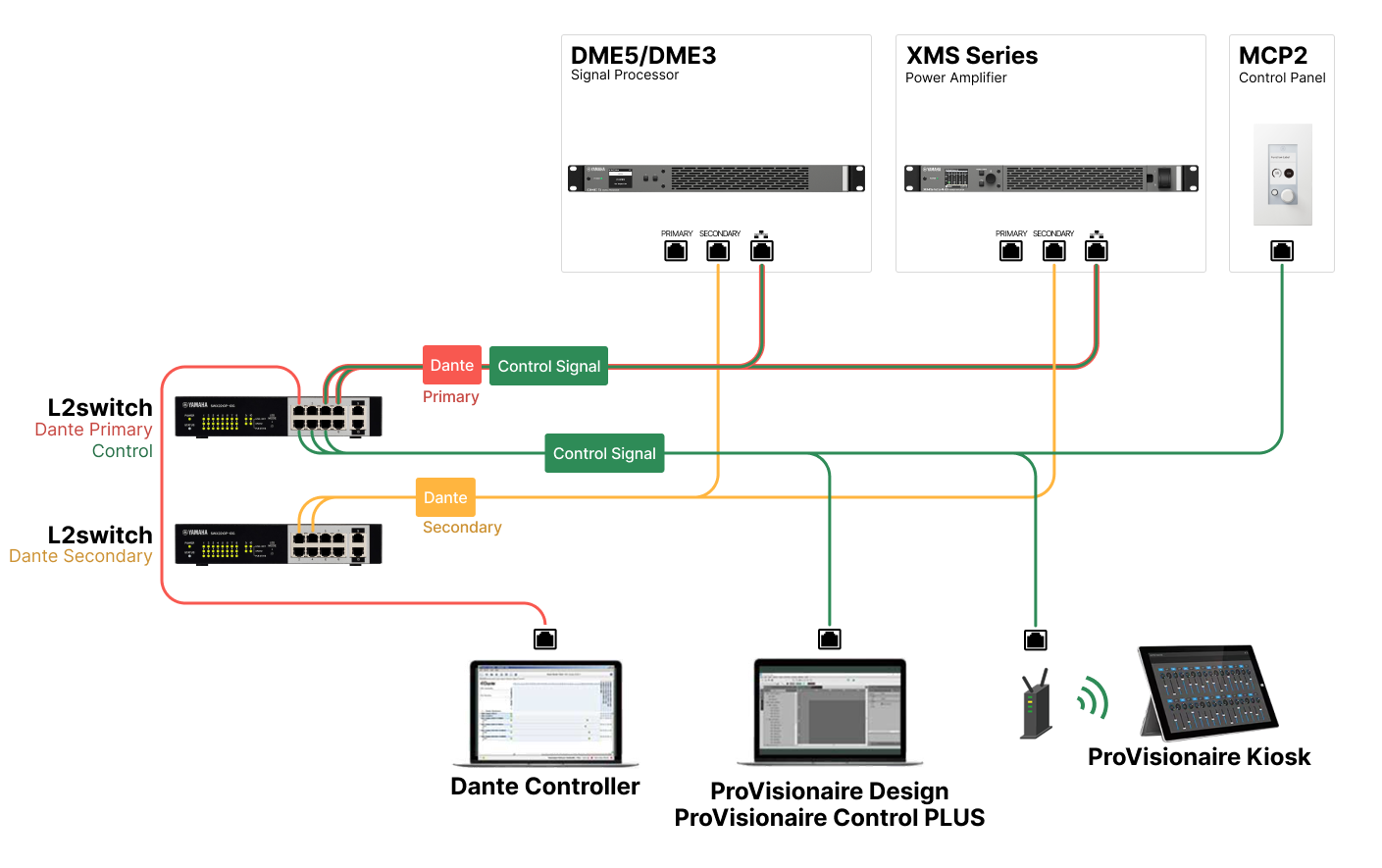
Daisy chain connection
A daisy chain is a method of connecting devices to form a chain where each device links to the next one. It can easily build a network and does not require a network switch.
As the number of connected devices increases, the transmission delay between end devices increases. To prevent audio dropouts on the Dante network, the higher latency must be set. Furthermore, if a system failure occurs due to a broken cable or other reason, the network will be divided at that point, which disables transmission to the devices beyond that point.
The number of Dante devices that can be connected in a single daisy chain should be up to five when the latency is set to the default (0.5 msec). If more than six devices are connected, communication delays within the network may increase, interrupting audio. To avoid this interruption, set Dante LATENCY to a larger value, or use an L2 switch (compatible with Gigabit Ethernet) to branch the network.
■ When Control is set to Separated
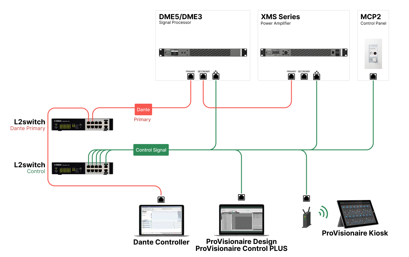
NOTICE
Do not connect multiple connectors to the same external switch, as this will create a network loop.
■ When Control is set to Merged
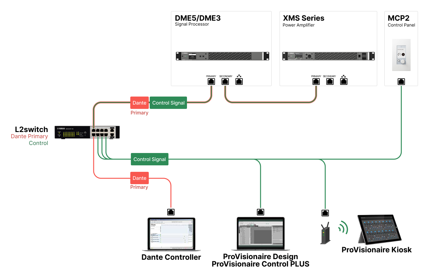
To summarize, the differences in characteristics are as shown in the table below.
|
CONTROL
|
|||
|---|---|---|---|
|
MERGED
|
SEPARATED
|
||
|
SECONDARY Port |
REDUNDANT |
|
|
|
DAISY CHAIN |
|
|
|
About Dante Controller
Dante Controller is application software for configuring Dante networks and routing audio. When connecting to a Dante device other than Yamaha digital mixers that support integration with the XMS series, or when configuring more detailed settings, use Dante Controller.
Download the latest version of Dante Controller from the following website.
https://www.audinate.com/
The computer on which to install Dante Controller must have an Ethernet connector that supports Gigabit Ethernet.
Dante Controller mainly allows you to configure the following settings:
• Input/output patch settings in the Routing tab of Network View
• Leader Clock settings in the Clock Status tab of Network View
• Sampling frequency settings in the Device Config tab of Device View
Dante Controller settings
When you start Dante Controller, Network View opens first.
Configure audio routing between Dante devices in Network View. This screen displays all Dante devices on the network. Click the cell [+] at the intersection of the transmitter and receiver devices to display all channels. Then, set the audio route. Once the route is established, a green checkbox icon will appear.
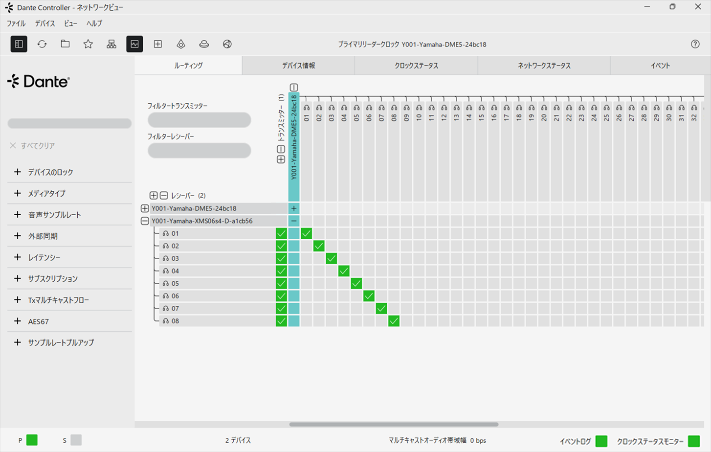
For details, refer to the Dante Controller user manual.
For information on which Dante channels the output of a transmitter device (such as a digital mixer) is assigned to, refer to the manual for the transmitter device and other references.
3.2.5. For external control: [REMOTE] connector and [FAULT OUTPUT] connector

This section explains how to use and connect the [REMOTE] connector and [FAULT OUTPUT] connector on the rear panel.
The three pins on the left are the [REMOTE] connector, and the three pins on the right are the [FAULT OUTPUT] connector.

■ How to use the [REMOTE] connector (3-pin Euroblock)
By connecting a switch to the [REMOTE] connector on the rear panel, you can remotely mute or unmute all channels and switch the power between sleep and power-on. The [REMOTE] connector consists of, from left to right, MUTE ALL, SLEEP, and GND. The [REMOTE] connector uses a Euroblock plug (3.5 mm pitch, 3-pin). For details on how to connect Euroblock plugs, refer to “ Connecting to the [REMOTE] connector and [FAULT OUTPUT] connector .”
To mute or unmute all channels
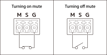
NOTE
If all channels are muted using the [REMOTE] connector, you cannot use the buttons or knobs on the front panel to mute or unmute the channels.
To switch the power between sleep and power-on
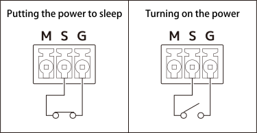
NOTE
If the power is put into sleep mode using the [REMOTE] connector, the power will go into sleep mode when you turn on the power switch on the front panel.
■ How to use the [FAULT OUTPUT] connector (3-pin Euroblock)
You can connect a lamp or other device to the [FAULT OUTPUT] connector on the rear panel to notify you of any abnormalities.
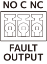
The [FAULT OUTPUT] connector consists of NO (Normally Open), C (Common), and NC (Normally Close). The [FAULT OUTPUT] connector is a relay circuit that operates as follows:
| Normal state | Abnormal state | Power-off state | |
|---|---|---|---|
|
NO |
Open |
Closed |
Closed |
|
NC |
Closed |
Open |
Open |
The [FAULT OUTPUT] connector uses a Euroblock plug. For details on how to connect Euroblock plugs, refer to “ Connecting to the [REMOTE] connector and [FAULT OUTPUT] connector .”
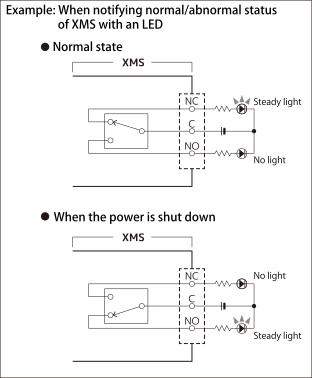
CAUTION
The rated load of the relay contact is 1 A, 30 VDC with a resistor load. Do not apply a load exceeding this value.
■ Connecting to the [REMOTE] connector and [FAULT OUTPUT] connector
Be sure to use the included Euroblock plugs to connect the [REMOTE] connector and [FAULT OUTPUT] connector. If you lose the plug, contact the repair support center or the store where you purchased the product.
Items to use
-
3-pin Euroblock plug (included)
-
Cable tie (included)
-
Cable to be connected (Handle the cable as follows.)
Cable handling
|
|
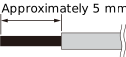
When connecting a cable to a Euroblock plug, strip the cable as shown in the illustration.
|
|
|
If you use portable equipment and frequently plug and unplug cables, we recommend using a rod terminal with an insulating sleeve or a ferrule terminal. Use the rod terminal whose conductor part has an outer diameter of 1.3 mm or less and a length of approximately 5 mm (such as AI 0,5 - 6 WH manufactured by Phoenix Contact). |
CAUTION
-
If you use stranded wire, do not solder the wire.
Connection procedure
The procedure is the same as Connection procedure for the INPUT connector.
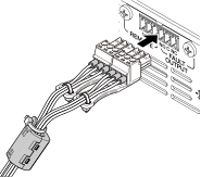
Attaching the ferrite core
To prevent electromagnetic interference, attach the included ferrite core to the cables for the [REMOTE] connector and [FAULT OUTPUT] connector by following the steps below.
Items to use
-
Ferrite core (included)
-
Cable tie (included)
Installation method
-
Pull the tabs.

-
Open the ferrite core.

-
Pass the cable through the ferrite core as shown in the illustration.

-
Close the ferrite core.
Make sure that both of the two ferrite core tabs are locked.
-
Use the cable tie to secure the cable to the tab.
Cut off any unnecessary parts of the cable tie as needed.
3.2.6. Connecting the power cord
NOTICE
Turn off the power switch before you connect the power cord.
Connect the included power cord in the following order.
-
Connect the included power cord plug to the AC IN connector.
-
Connect the plug on the other end of the power cord to an AC outlet.
WARNING
-
This product is designed to be connected to earth ground. To prevent electric shock and damage to the device, use the power cord included with the product to ensure a reliable earth ground connection. If you are unsure how to connect, contact the repair support center.
-
Be sure to use the power cord included with the product. Using any other power cord may result in overheating or electric shock.
When disconnecting the power cord, first unplug the power plug from the outlet, then unplug the power cord from the main unit.
3.3. Turning on the power
CAUTION
Before turning on the power, make sure that no audio signal is present in the analog input connector. If any audio signal is present, excessive input may be applied to the speakers when the power is turned on, which may damage the speaker system or cause ear strain due to the loud volume. Also, if any abnormality occurs in the speakers or wiring, the protection circuit will be activated immediately after the power is turned on. Check to see if there are any problems with the wiring, etc.
Turn on the power using the power switch on the front panel.

When the power switch is on, you can also change to power-saving sleep mode ( POWER SUPPLY ). To power on the device from sleep mode, press the main knob to display the confirmation screen, then select OK.
NOTE
-
You can set whether to start the unit always in the power-on state when you press the power switch, or to start the unit in the same state as the last time (power-on or sleep) ( POWER ON DEFAULT ).
The settings are saved when the power is turned off (in the state where the cord is unplugged from the power outlet). When you turn the power back on, the product will start up with the setting values saved.
3.4. Setup
NOTE
You can also set up XMS in ProVisionaire Design. For details, refer to the manuals below.
ProVisionaire Design User Guide
This guide introduces the general settings available in ProVisionaire Design.
New CIS Ecosystem Setup Guide (Workflow Edition)
This guide explains the workflow for building a system using New CIS Ecosystem products, including the XMS series, and ProVisionaire Design.
3.4.1. Device identification information
Setting the UNIT ID
When connecting to ProVisionaire Design, you need to set an ID for identifying the XMS series on the network. The factory default setting is 01. If the same models are present in one network, make sure that the IDs do not overlap. The set UNIT ID will become effective after this product is restarted.
-
Move the cursor to UNIT ID on the HOME screen and press the main knob.
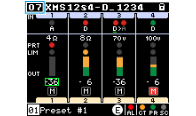
-
Select “UNIT ID” and press the main knob.
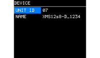
-
Turn the main knob to select the character you want to enter, and press the main knob to confirm the character.
-
Select YES on the restart confirmation screen. After the restart, the set UNIT ID will be displayed on the HOME screen.
Setting the DEVICE NAME
When connecting to ProVisionaire Design, set a device name for this product so that you can identify it in the app. The default setting is a combination of the model name and a number.
-
Move the cursor to DEVICE NAME on the HOME screen and press the main knob.
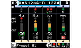
-
Select “NAME” and press the main knob.
-
Set the device name for this product.
NOTE
-
You can enter a name up to 32 characters long.
-
The characters you can enter are as follows:
ABCDEFGHIJKLMNOPQRSTUVWXYZ
abcdefghijklmnopqrstuvwxyz
0123456789
! “ # $ % & ‘ ( ) * + , - . / : ; < = > ? @ [ \ ] ^ _ ` { | } ~ (space) -
Other characters entered in ProVisionaire Design will be displayed as a “□” mark.
-
-
Select YES on the restart confirmation screen. After the restart, the set device name will be displayed on the HOME screen.
3.4.2. Audio input
Setting input switching
Open the settings screen by selecting MENU screen → SETUP → INPUT SETTINGS → INPUT SOURCE SELECT , and set the input source for each channel.
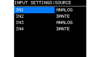
Also, check that the following settings are appropriate:
● For analog
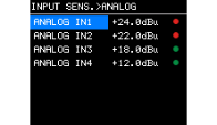
・SENSITIVITY (Input sensitivity)
MENU screen → SETUP → INPUT SETTINGS →
INPUT SENSITIVITY
● For Dante
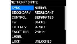
・Fs (Dante input/output sampling frequency)
MENU screen → NETWORK → Dante → Fs
The default setting is 96 kHz.
・SECONDARY (Redundant connection/daisy chain connection)
MENU screen → NETWORK → Dante → SECONDARY
The default setting is redundant connection.
3.4.3. Routing
Set the audio signal routing. You can sum multiple input signals.
For the setting, go to the MENU screen → PROCESSING → ROUTER.
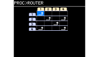
Check the input source (IN1-8 or IN1-4) and output destination (OUTPUT), and set [
 ] at the intersection point.
By default, signals from all input connectors are output from the speaker with the same channel number.
3.4.4. Audio output (Speaker)
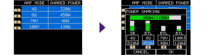
Check that the amplifier mode and power allocation (power sharing) are appropriate for the speakers to be connected.
The default setting for amplifier mode is 8 Ω. To set the value to 4 Ω or use a high-impedance connection, the setting needs to be changed.
The default power sharing settings for each channel are as follows:
・XMS24s8/-D, XMS12s4/-D: 300 W
・XMS12s8/-D, XMS06s4/-D: 150 W
For the setting, go to the MENU screen → SETUP → AMP SETTINGS → MODE/POWER-SHARING.
● Setting the amplifier mode
Select from 4 Ω, 8 Ω, 70 V, or 100 V according to the impedance of the speaker to be connected.
● Setting power sharing
Set the required power for each channel. Allocation is set by four-channel group.
For details, refer to
“POWER SHARING”
at the beginning of this manual and the explanation of the
MODE/POWER SHARING screen
.
3.4.5. Checking the wiring
This section explains how to change the volume value and mute/unmute method, which are necessary for checking the wiring. Before checking the connections, we recommend setting the volume values of all channels to the minimum to prevent speaker damage and other issues. Check the wiring while audio signals are being output from a mixer or other device connected to the analog input connector.
NOTE
Check the INPUT SOURCE(Redundant) & SIGNAL indicator on the HOME screen to confirm that the input signals are correctly received.
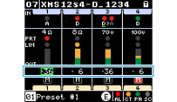
● Changing the volume
Select the volume on the HOME screen and adjust it by turning the main knob.
● Procedure for switching between mute and unmute
To switch between mute and unmute for each channel, move the cursor to the desired channel on the HOME screen and simultaneously press the main knob and [
 ] (Back) button.
When a channel is muted, the mute icon on the screen will light up red.
NOTE
Even if the signal output cannot be easily checked because the speaker is installed in a remote location, you can use OUTPUT METER on the HOME screen to check whether voltage is applied to the speaker.