Making connections
Making connections
Connecting to the [GPI] ports
Connect GPI (General Purpose Interface) devices to the [GPI] ports on the rear panel. GPI is used to input/output control signals with external devices such as controllers.
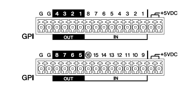
The DME7 has 16 input terminals and 8 output terminals.
-
The output voltage of the +5 V DC terminal is 5 V. The maximum total current that can be drawn from the two ports is 100 mA.
If a switch/variable resistor and an LED/relay are to be used at the same time, connect the switch/variable resistor to one port and the LED/relay to the other port. -
At [IN] terminals 1 to 15, voltages between 0 and 5 V are detected. Only at [IN] terminal 16, +24 V input is supported, and voltages between 2.5 V
and 24 V are identified as high and voltages below 2.5 V as low. -
[OUT] terminals 1 to 8 are open collector outputs, which switch between open and ground. The maximum voltage that can be applied is +12 V. The maximum allowable current is 75 mA per port.
Use ProVisionaire Design to specify settings such as parameters to be assigned to GPI controllers.
![]() NOTE
NOTE
-
Specifying input/output channels in ProVisionaire Design allows presets from a connected GPI external device to be recalled, parameters to be changed, and signals to be sent to GPI external devices. For details on specifying settings, refer to the ProVisionaire Design User Guide.
https://manual.yamaha.com/pa/pv/pvd/
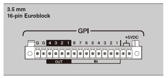
Connecting a Euroblock plug
Use the included Euroblock plugs to connect to the [GPI] ports.
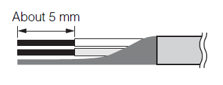
Preparing cable wires
The cable wires to be connected to the Euroblock plug should be stripped as shown and twisted.
Note that the cable wire strands connected to Euroblock plugs may easily break due to metal fatigue caused by the weight of the cable or vibration.
![]() Caution
Caution
-
Do not apply solder to stranded wires.
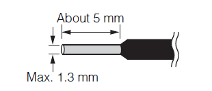
If wires will be frequently disconnected and reconnected as in a portable setup, the use of pin terminals with insulation sleeves is recommended. Use pin terminals with a conductor portion as shown below.
With an outer diameter of 1.3 mm or less and a length of about 5 mm (such as AI0, 5-6WH manufactured by Phoenix Contact)
-
Push in the Euroblock plug until it is firmly seated in the [GPI] port on this device, and then raise the left and right locks.
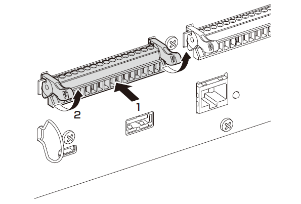
-
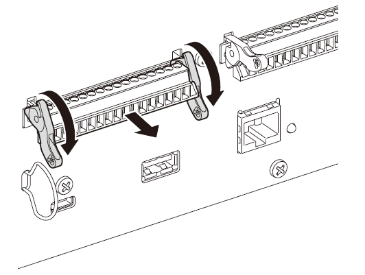
To remove a Euroblock plug, lower the left and right locks, and then pull out the plug.
Installing the cable hook
A cable hook is provided to prevent accidental disconnection of the USB cable. To attach the cable hook, follow the steps below.
-
Hook one end of the included cable hook onto the lower end of the security slot, located in the lower-left area of the rear panel.
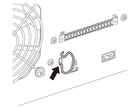
-
Insert the other end of the hook into the upper end of the security slot.
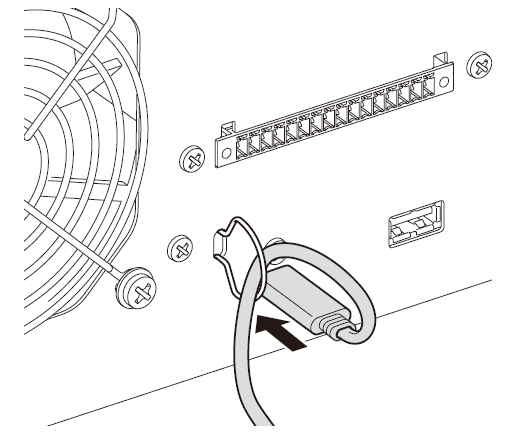
-
Insert the USB cable through the hook, and then connect it to the USB port.