Dialog boxes
10. Dialog boxes
This chapter explains the dialog boxes and windows that you can open from the menu bar or tool bar.
10.1. "Network Setup" dialog box
Here you can select the computer’s network interface card (subsequently called the "network card") used for communicating with devices.
You can also change the IP address of the network card.
|
If you’re not using a DHCP server, fix the IP address of your computer’s network card. We recommend the following settings.
IP address: 192.168.0.253 Subnet mask: 255.255.255.0 |
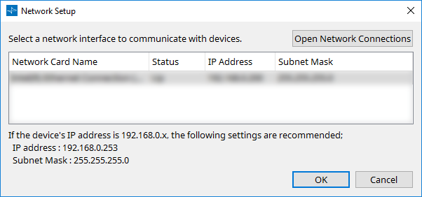
If the computer is not connected to the network, click the [Cancel] button to close the dialog box.
-
Network Card Name
Shows the name of the network card. -
Status
Shows the status of the network card (Up or Down).
A network card indicated as "Down" cannot be selected. -
IP Address and Subnet Mask
Indicates the IP address and subnet mask that are assigned to the network card.
Select a network card of the same subnet as the devices. -
[Open Network Connections] button
Opens the control panel "Network Connections." Use this when you want to change the IP address of the network card. -
[OK] button
Updates the settings and closes the dialog box. -
[Cancel] button
Closes the dialog box without updating the settings.
10.2. Startup dialog box
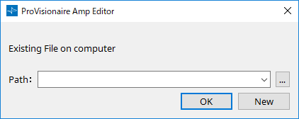
This appears when ProVisionaire Amp Editor starts.
-
[Path] pulldown menu
Lets you view and select a recently saved project file. -
[…] button
Opens the "Select File" dialog box. Select the project file that you want to load. -
[OK] button
Loads the project file that is shown in the [Path] pulldown menu. -
[New] button
Starts a new project.
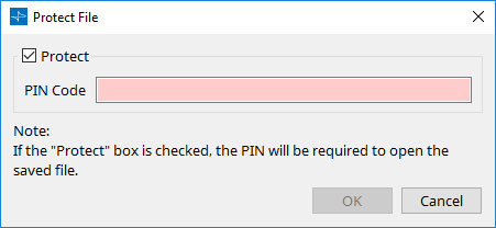
10.3. "Protect File" dialog box
In ProVisionaire Amp Editor, you can specify a PIN code (secret number) for security.
-
[Protect] check box
If this check box is selected, the "Security" dialog box will appear when the project file starts.
If this check box is cleared, all users will be able to open the project file. -
[PIN Code]
If the [Protect] check box is selected, enter the password (a secret number of four single-byte numerals).
You cannot enter anything other than single-byte numerals, nor can you enter a blank PIN code.
|
- The PIN code can be viewed in this dialog box. Make sure that it is not seen by another user.
- If you forget the PIN code, you will be unable to open the corresponding project file. |
-
[OK] button
Updates the settings and closes the dialog box. -
[Cancel] button
Closes the dialog box without updating the settings.
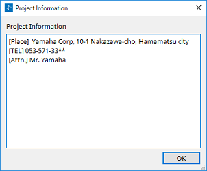
10.4. "Project Information" dialog box
Allows you to include a memo in the project file to record property information or contact information.
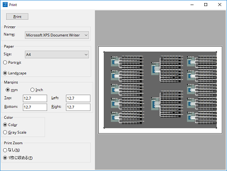
10.5. "Print" dialog box
Here you can make settings related to printing a sheet, specify the size of paper shown on the sheet, and see a print preview.
-
[Print] button
Click this to open the Windows "Print" dialog box. -
Printer
-
[Name] list box
Specifies the printer to use.
-
-
Paper
-
[Size] list box
Specifies the size of the paper. If the [View] menu item [Print Area] has a check mark, the size of paper shown on the design sheet follows this setting. -
[Portrait]/[Landscape] option buttons
Specify the orientation of the paper. The orientation of the paper shown on the design sheet follows this setting.
-
-
Margins
-
[mm]/[Inch] option buttons
Specify the units for the top, bottom, left, and right margins. -
[Top]/[Bottom]/[Left]/[Right] text boxes
Specify the top, bottom, left, and right margins.
-
-
Color
-
[Color]/[Gray Scale] option buttons
Specify whether to print in color or in gray scale.
-
-
Print Zoom
-
[None]/[Fit on one page] option buttons
Specify either that the printed content will be the region within the paper shown on the design sheet, or that the entire sheet will be reduced in size to fit on a single page.
-
-
Preview area
Shows a print preview.
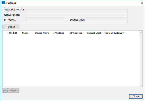
10.6. "IP Settings" dialog box
Lists the devices found on the network, allowing you to change their IP address.
-
"Network Interface"
Shows the name/IP address/subnet mask of the network card currently selected in the "Network Setup" dialog box. -
[Refresh] button
Searches again for devices on the network. -
Device list
-
Identify button
When you press this button located at the left of the UNIT ID, the indicators of the corresponding device will flash for several seconds. -
Unit ID
Shows the UNIT ID of the device.
If there is a UNIT ID conflict, an indication is shown.
-
Model
Indicates the model name of the device. -
Device Name
Shows the device name. This name can be edited in the "Project" sheet’s "Properties" area, using [Device Name]. -
IP Settings
Indicates whether the IP address setting is Unit ID mode, Static IP mode, or DHCP mode. -
IP Address/MAC Address/Subnet Mask/Default Gateway
Indicates the IP address, MAC address, subnet mask, and default gateway that are specified for the device.
-
-
[Set IP Address] button
Opens the "IP Address" dialog box . -
[Close] button
Closes the dialog box.
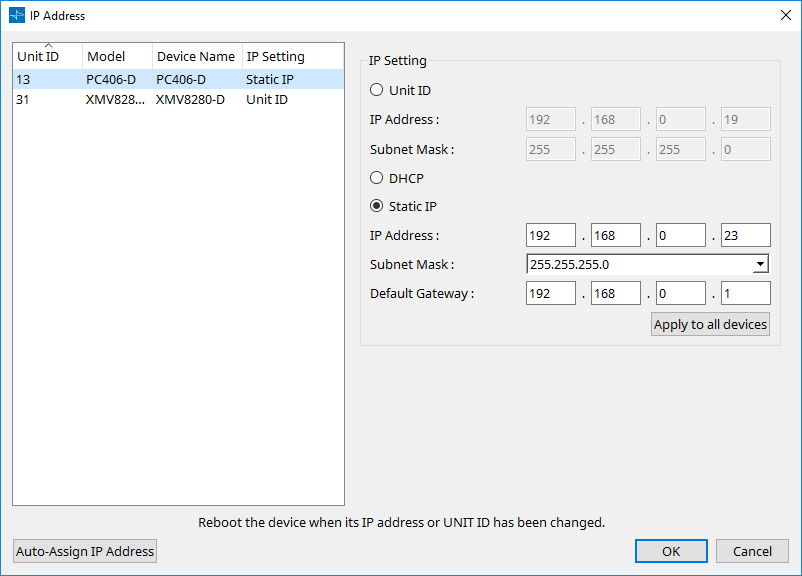
10.7. "IP Address" dialog box
Here you can set the device’s IP settings.
Set this so that there is no conflict between devices.
Editing is not possible while online.
In order to use ProVisionaire Amp Editor to control devices of differing subnets, it is necessary to operate the devices using fixed IP addresses. For details, refer to
"Settings for controlling devices across subnets"
.
10.7.1. For PC-series devices
-
Device list
Shows the devices on the network. When you select this, the settings of the current device are shown in the right, allowing you to edit them. -
IP Setting
-
[Unit ID] option button
Automatically assigns the IP address based on the UNIT ID of the device.
This assigns the IP address as 192.168.0.UNIT ID and the subnet mask as 255.255.255.0. -
[DHCP] option button
Choose this if you want the DHCP server to assign the IP address.
If there is no DHCP server, the IP address will be assigned as a link-local address. -
[Static IP] option button
Assigns a fixed IP address for the device. -
[Default Gateway] text box
Assigns the IP address of the default gateway. -
[Apply to all the devices] button
Applies the settings of the [Unit ID] option button, [DHCP] option button, and [Static IP] option button to all PC-series devices.
If the [Static IP] option button is selected, the "IP Address" setting is not applied.
-
-
[Auto-Assign IP Addresses] button
Click this to open the "Auto-Assign IP Addresses" dialog box . -
[OK] button
Transmits the settings to the device, and closes the dialog box.
If you change the IP address, the device will restart, and communication will be temporarily interrupted. -
[Cancel] button
Discards the settings and closes the dialog box.
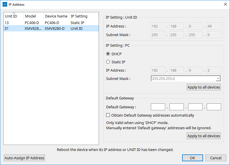
10.7.2. For XMV-series devices
-
Device list
Shows the devices on the network. When you click this, the settings of the current device are shown in the right, allowing you to edit them. -
IP Setting: Unit ID
If the device’s rear panel DIP switch IP Setting is [UNIT ID] mode, it uses the displayed IP Setting. -
IP Setting: PC
If the device’s rear panel DIP switch IP Setting is [PC] mode, use ProVisionaire Amp Editor to switch between DHCP or Static IP.-
[DHCP] option button
Choose this if you want the DHCP server to assign the IP address.
If there is no DHCP server, the IP address is not set. To solve this problem, check that the DHCP server is connected. Alternatively, use the rear panel DIP switches of the device to set IP Setting to [UNIT ID] (the mode in which the IP address will be generated from the UNIT ID]. -
[Static IP] option button
If the unit’s IP Setting is "STATIC IP," the IP address and subnet mask are shown and can be edited. -
[Apply to all the devices] button
Applies the settings of the [DHCP] option button and [Static IP] option button to all XMV-series devices.
-
-
Default Gateway
-
[Default Gateway] text box
Specifies the IP address of the default gateway. -
[Obtain Default Gateway and DNS Server address automatically] check box
If this check box is selected, the IP address of the default gateway is obtained automatically. The above IP address setting for the default gateway is ignored. -
[Apply to all the devices] button
Specifies the same default gateway for all devices shown in the device list.
-
-
[Auto-Assign IP Addresses] button
Click this to open the "Auto-Assign IP Addresses" dialog box . -
[OK] button
Transmits the settings to the device, and closes the dialog box.
If the device’s IP Setting is [Static IP] and you’ve changed the IP address, communication will be temporarily interrupted. -
[Cancel] button
Discards the settings and closes the dialog box.
| If you don’t know the network address of the unit, we recommend that you use the DIP switch to set IP Setting to [UNIT ID]. |
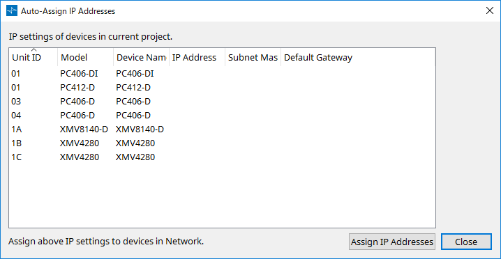
10.8. "Auto-Assign IP Addresses" dialog box
Information such as the IP address assigned to virtual devices specified in the "Match Devices by IP Address" dialog box is applied to the "IP Settings" dialog box in a single operation.
For details, refer to
"Settings for controlling devices across subnets"
.
-
Device list
Shows the devices for assignment and the IP settings to be assigned. -
[Assign IP Addresses] button
Applies the information shown in the device list to the "IP Address" dialog box. Even if the [DHCP] option button is selected in the "IP Address" dialog box, the [Static IP] option button is switched to the enabled state. -
[Cancel] button
Closes the dialog box.
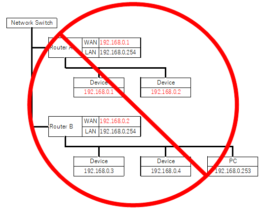
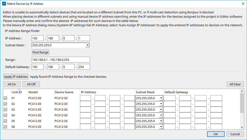
10.9. "Match Devices by IP Address" dialog box
When you assign an IP address to a virtual device in this dialog box, ProVisionaire Amp Editor searches for devices on the network by IP address.
If you want to control a system that is on a different subnet than ProVisionaire Amp Editor, make settings here.
For the procedure, refer to
"Settings for controlling devices across subnets"
.
Dante audio communication is not possible between devices that are on different subnets.
Set the IP addresses so that they are unique for the entire communication path. If devices of the same IP address exist on the communication path, they might not be distinguishable.
-
IP Address Range Finder
If it is OK for the IP addresses to be consecutive, you can use this to calculate the IP addresses for assignment.-
[IP Address:]
Enter the IP address that you want to use. -
[Subnet Mask:]
Select the subnet mask. -
[Find Range] button
When you click this, the range that can be specified is calculated from the IP address and subnet mask that you input. -
"Range"
Shows the calculated range of IP addresses. -
Default Gateway
Shows the calculated default gateway.
-
-
[Apply IP Address] button
When you click this, the IP address calculated in "IP Address Range Finder" and the default gateway are applied to the devices in the device list. -
[All On] button
Selects all devices in the device list to be affected by [Apply IP Address]. -
[All Off] button
Deselects all devices in the device list from being affected by [Apply IP Address]. -
[All Clear] button
Deletes the IP address information of the devices. -
Device list
Here you can view and edit the settings of the devices in the device list.-
Check box
If this is selected, [Apply IP Address] will apply to this device. -
[IP Address]/[Subnet Mask]/[Default Gateway]
Here you can view and edit the device’s IP address, subnet mask, and default gateway.
-
-
[OK] button
Applies the settings and closes the dialog box. -
[Cancel] button
Discards the settings and closes the dialog box.
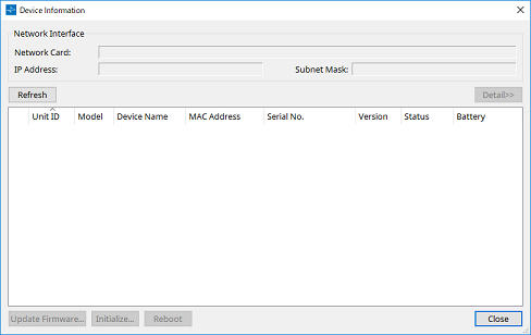
10.10. "Device Information" dialog box
This lists information for the devices on the network, allowing you to update their firmware or restart them.
-
Network Interface
Shows the name/IP address/subnet mask of the network card currently selected in the "Network Setup" dialog box. -
[Refresh] button
Searches again for devices on the network.
This cannot be clicked while an update is in progress. -
[Detail>>] button (XMV only)
Shows details about the device. -
Device list
-
Identify button
When you press this button located at the left of the Unit ID, the indicators of the corresponding device will flash for several seconds. -
Unit ID
Shows the UNIT ID of the device.
If there is a UNIT ID conflict, an
indication is shown.
-
Model
Indicates the model name of the device. -
Device Name
Shows the device name. This name can be edited in the "Project" sheet’s "Properties" area, using [Device Name]. -
MAC Address
Shows the MAC address that is specified for the device. -
Serial No.
Shows the serial number of the device. -
Version
Shows the firmware version. -
Status
Shows the online or offline status.
When updating a device, the progress is shown. -
Battery
Shows the remaining battery capacity of the XMV-series device.
-
|
EMPTY |
The remaining amount is 0–0.5V. Immediately stop using the unit, and contact a Yamaha service center. |
|
LOW |
The remaining amount is 0.5–2.5V. Contact a Yamaha service center as soon as possible. |
|
OK |
The remaining amount is 2.5–3.5V. There is no problem. |
|
N/A |
There is no internal battery. |
-
[Update Firmware] button
Updates the firmware.
Click this button to open the "Update Firmware" dialog box. -
[Initialize] button
Initializes the device. -
[Reboot] button
Reboots the device. -
[Close] button
Closes the dialog box.
This cannot be clicked while an update is in progress.
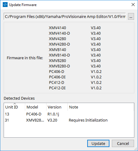
10.11. "Update Firmware" dialog box
This dialog box lets you update the firmware of a supported unit.
For details on how to update the Dante firmware, refer to the Dante Firmware Update Manager user guide "AUD-MAN-Firmware_Update_Manager-vX.Xja.pdf (vX.X is the user guide version )."
-
Files
Shows the currently selected update file (.fupd). -
[…] button
Click this button to select an update file. Clicking this button opens the "Select Folder" dialog box; select an .fupd file. -
Firmware in this file
Shows the contents of the update file. -
Detected Devices
Shows the detected devices.
|
Unit ID |
Indicates the UNIT ID of the device. |
|
Type |
Indicates the model name of the device. |
|
Version |
Shows the firmware version of the device. |
-
[Update] button
Executes the update.
If a file is not selected, this button will be unavailable and cannot be clicked. -
[Cancel] button
Closes the dialog box without updating.
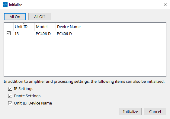
10.12. "Initialize" dialog box
Initializes the settings of the PC-series device.
-
[All On] button
Adds a check mark for all devices in the list. -
[All Off] button
Clears the check mark for all devices in the list. -
Device list
Shows the devices detected by ProVisionaire Amp Editor.-
Check box
Add a check mark to each device that you want to initialize. -
Unit ID
Indicates the UNIT ID of the device. -
Model
Indicates the model name of the device. -
Device Name
Indicates the device name. -
IP Settings
If this is checked, the IP settings of the device are also initialized. -
Unit ID, Device Name
If this is checked, the UNIT ID and device name of the device are also initialized. -
Dante Settings
If this is checked, the Dante-related settings of the device are also initialized. -
[Initialize] button
Executes initialization of the devices that have a check mark. -
[Cancel] button
Closes the dialog box without executing initialization.
-
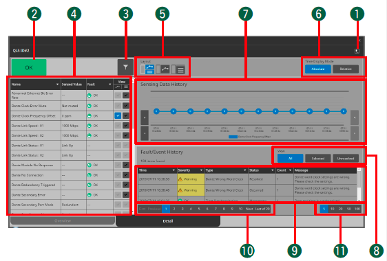
10.13. "ProVisionaire Monitoring Service" window
"ProVisionaire Monitoring Service" is software that monitors the status of compatible devices in the network, and continues collecting information.
Information from "ProVisionaire Monitoring Service" running on another computer can also be shown. In this case, settings are made in
"ProVisionaire Monitoring Service Setup" dialog box
.
You can decide whether to install "ProVisionaire Monitoring Service" when installing the following software.
* ProVisionaire Amp Editor
* ProVisionaire Control (V3.5.0 and later)
* ProVisionaire Control KIOSK (V3.5.0 and later)
For details on compatible devices, refer to the web pages for ProVisionaire Amp Editor or ProVisionaire Control.
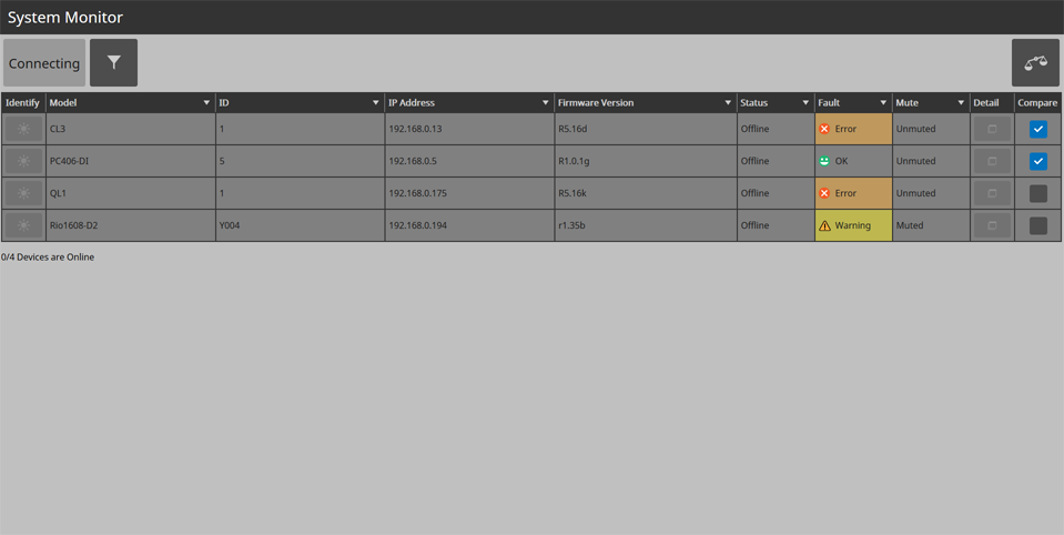
10.13.1. Device list
Lists the compatible devices that are connected.
By clicking the [▽] in each column, you can sort or filter by keyword.
-
Status indicator
This indicates the highest level of fault for all connected devices. If there is no fault, this indicates "OK." -
Filter button (
 )
)
Only the devices for which a fault has occurred are shown. -
Compare button(
 )
)
Operating information for devices whose [Compare] check box is selected in the device list is shown together in the "Compare Devices" screen. For an explanation of the "Compare Devices" screen, refer to the contents of the [Detail] tab in "Device details" below. -
Device list
-
[ Identify] button
When you click this, the indicators of the device flash for several seconds. -
[ Model]
Indicates the model name of the device. -
[ID]
Indicates the UNIT ID of the device. -
[IP Address]
Indicates the IP address of the device. -
[Firmware Version]
Shows the MAIN firmware version of the device. -
[Status]
Indicates whether the device is powered-on and whether it is online. -
[Fault]
Indicates the fault that is occurring on the device. -
[Mute]
Indicates whether the fault has caused the device to be muted. Depending on the condition of the device, it might be muted or unmuted automatically. -
[Detail] button
Shows detailed information for the device. -
[Compare] check box
Operating information for the devices whose check box is selected is shown together in the "Compare Devices" screen. To access the "Compare Devices" screen, click the compare button.
-
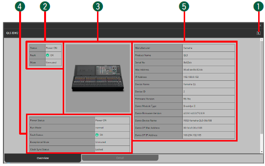
10.13.2. Device details
Shows detailed information for the device.
Overview shows information for the device, and Detail shows information about the device’s operating status.
[Overview] tab
-
Back button (
 )
)
Returns to the device list. -
Summary of device status
Shows a simplified view of the device status. -
Device image
Shows a graphic of the currently-viewed device. -
Status of entire device
Shows a simplified view of the overall status of the device. -
Device profile
Shows a profile of the device, including its firmware version.
[Detail] tab
-
Back button (
)
Returns to the device list. -
Status indicator
This indicates the highest level of fault for the device. If there is no fault, this indicates "OK." -
Filter button (
)
Only the items for which a fault has occurred are shown. -
Item list
This is a list of the operating status information that is being monitored. By clicking the [▽] in each column, you can sort or filter by keyword.-
[Name]
These are the names of the operating status items that are being monitored. -
[Sensed Value]
This shows the operating status information. -
[Fault]
Indicates the fault that is occurring on the device. -
[View]
Add a check mark to the items that you want to be shown in "Sensing Data History" or "Fault/Event History."
-
-
[Layout] button(
 )
)
Switches the layout of the "Sensing Data History" and "Fault/Event History" display. -
Time Display Mode
Selects the type of time information shown in the "Sensing Data History" graph and "Fault/Event History." [Absolute] shows absolute time expressed as a date and hours/minutes/seconds, and [Relative] shows the cumulative number of occurrences and the time elapsed since startup. -
"Sensing Data History" graph
The items that are checked in the [View] item list are shown as a graph.-
[|◁]/[◁] buttons
Shows the time span earlier than the currently shown time. -
[▷|]/[▷] buttons
Shows the time span later than the currently shown time.
-
-
View [All]/[Selected]/[Unresolved] buttons
If [All] is selected, all alerts and events saved in ProVisionaire Monitoring Service are shown.
If [Selected] is selected, the items that are checked in the [View] item list are shown.
If [Unresolved] is selected, only the unresolved faults and events are shown. -
Item list
Shows information for the faults and events that occurred. By clicking the [▽] in each column, you can sort or select the items that are shown.-
[Time]
Shows the date and time at which the faults and events occurred. -
[Severity]
Shows the severity of the faults and events that occurred. -
[Type]
Shows the type of faults and events that occurred. -
[Status]
Shows the current status of the fault. -
[Count]
Shows the number of times that the same fault or event occurred before the following fault or event occurred. -
[Message]
Shows detailed information for the faults that occurred.
-
-
Pagination button
Switches between types of faults or events shown in the item list. -
Buttons to change the number of items displayed
Specify the maximum number of faults or events that are shown in the item list.
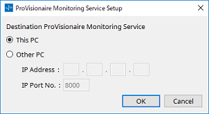
10.14. "ProVisionaire Monitoring Service Setup" dialog box
Here you can specify the computer that is running "ProVisionaire Monitoring Service."
You can also specify a computer other than the one that is running ProVisionaire Amp Editor.
-
[This PC] option button
Makes the "ProVisionaire Monitoring Service View" window show the device operating status information collected by the computer that you are currently operating. -
[Other PC] option button
Makes the "ProVisionaire Monitoring Service View" window show the device operating status information collected by another computer.-
[IP Address] text box
Enter the IP address of the computer that is used if the [Other PC] option button is enabled. -
[IP Port No.] text box
Enter the port number used by "ProVisionaire Monitoring Service" on the other computer.
If you use the [TCP port number for view of ProVisionaire Monitoring Service] spin box/text box to manually change the port number in "ProVisionaire Monitoring Service Settings" screen of the other computer, you must also change the firewall settings of the other computer.
In the case of "Windows Defender firewall," use the following procedure to change these settings.-
[Start] menu→[Windows System Tools]→[Control Panel]→([System and Security]→)[Windows Defender Firewall]→ choose [Advanced settings].
The "Windows Defender Firewall" with Advanced Security" window appears. -
[Inbound Rules]→[ProVisionaire Monitoring Service]→choose [Properties].
The "ProVisionaire Monitoring Service Properties" dialog box appears. -
In the [Protocols and Ports] tab, change the local port to a value other than 50082.
Set the numeric value to the value that was specified in the [TCP port number for view of ProVisionaire Monitoring Service] spin box/text box.
50082 is for the "ProVisionaire Monitoring Service Settings" screen, so don’t use it here. -
Click the [OK] button.
The firewall settings will change.
-
-
-
[OK] button
Enables the settings and closes the dialog box. -
[Cancel] button
Discards the settings and closes the dialog box.
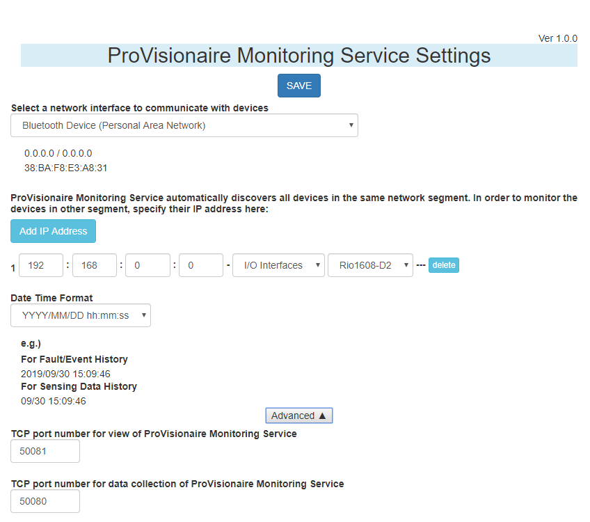
10.15. "ProVisionaire Monitoring Service Settings" screen
Here you can make settings for the ProVisionaire Monitoring Service that is installed on the computer.
Choose Windows [Start]→[Yamaha ProVisionaire Monitoring Service]→[ProVisionaire Monitoring Service Settings] to access it.
The window cannot be opened if the "Default web browser" is Internet Explorer. Specify the "Default web browser" as Microsoft Edge or Google Chrome.
-
[SAVE] button
Applies the settings to ProVisionaire Monitoring Service. -
[Select a network interface to communicate with devices] list box
Selects the network interface used to obtain device operating status information. -
[Add IP Address] button
Allows you to enter the IP address and model of a device that is on a different subnet.
If you also want to obtain information from a device that is on a different subnet, enter the device’s IP address etc. here.
If you click the [delete] button, the device information is deleted. -
[Date Time Format] list box
Selects the time format that is shown in the "ProVisionaire Monitoring Service" window’s "Sensing Data History" graph or in the "Fault/Event History" list. -
[Advanced] button
Shows or hides the detailed settings listed below. -
[TCP port number for view of ProVisionaire Monitoring Service] spin box/text box
Specifies the TCP port number used for passing the operating status information to another computer. If you change this, you must also change the Windows firewall settings. By default, this is set to "50081." -
[TCP port number for data collection of ProVisionaire Monitoring Service] spin box/text box
Specifies the TCP port number used for collecting the operating status information. If you change this, you must also change the Windows firewall settings. By default, this is set to "50080."
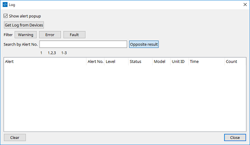
10.16. "Log" dialog box
Shows alert information communicated from the devices. The log is deleted when you exit ProVisionaire Amp Editor, or when you open another project file or create a new one.
-
[Show Alert Popup] check box
If this is selected, alert information is shown as a popup if an alert occurs. -
[Get Log from Devices] button (XMV series only)
Displays the "Get Log" dialog box. Obtains alert information from devices that store it internally, and saves it as CSV format. -
[Warning]/[Error]/[Fault] buttons
Alerts of the types whose button is on are not shown in the alert list. -
[Search by Alert No.] text box
Enter the alert numbers that you want to see in the alert list. -
[Opposite Result] button
If this is on, alerts other than those entered in the [Search by Alert No.] text box are shown in the alert list. -
Alert list
Shows a list of the alerts that were received from devices while ProVisionaire Amp Editor was running. When you click the title of a column, ∧/∨ symbols appear, allowing you to change the order in which the alerts are shown.-
Alert
Shows the contents of the alert and an icon. If an information button is shown, clicking it opens a "Solution" dialog box containing information about how to solve the problem. -
Alert No.
Shows the alert number. -
Severity
Shows the type of alert that occurred. -
Status
Shows the current status of the alert. -
Model
Shows the model name of the device. -
Unit ID
Shows the UNIT ID of the device. -
Time
Shows the time at which the alert occurred. -
Count
Shows the number of times that the alert occurred.
-
-
[Clear] button
Deletes the log shown in the alert list. -
[Close] button
Closes the dialog box.
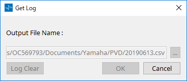
10.17. "Get Log" dialog box
Obtains fault information held within the XMV-series devices, and saves it in CSV format.
-
[Output File Name:] text box
Indicates the file selected by the […] button, as an absolute path. You can also enter this directly. -
[…] button
Opens a dialog box for the file in which the CSV format data will be saved. -
[Log Clear] button
Deletes the alert log held within the device. -
[OK] button
Writes the log to the file indicated by the [Output File Name:] text box, and closes the dialog box. -
[Cancel] button
Closes the dialog box without saving to the file.
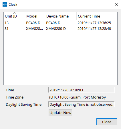
10.18. "Clock" dialog box
The date and time of the computer are transmitted to each connected device every time it goes online, automatically updating the internal clock of each device. If you transmit the computer’s date and time information from this dialog box, the date and time will be updated on the devices that are connected to the same network, regardless of the online/offline status.
-
Unit ID
Indicates the UNIT ID. -
Model
Indicates the model name of the device. -
Device Name
Indicates the device name. This name can be edited in the "Project" sheet’s "Properties" area, using [Device Name]. -
Current Time
Indicates the time information of the device. -
Time
Shows the date and time of the computer system clock that ignores the daylight saving time setting. -
Time Zone
Indicates the time zone setting of the computer. -
Daylight Saving Time
Shows the daylight saving time of the computer. If the daylight saving time setting has not been specified, this field will indicate "Daylight Saving Time has not been applied." -
[Update Now] button
When you click this, the device’s internal clock is updated according to the settings. -
[Close] button
Closes the dialog box.
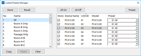
10.19. "Linked Presets Manager" window
In this window, settings for multiple devices equipped with a preset function can be stored or recalled in a single operation.
To close the window, click the [X] button in the upper right.
Basic use is as follows.
-
In the list at left, select the store-destination link preset.
-
In the list at right, add a check mark to the devices that you want to store.
-
Click the [Store] button.
The preset is stored in the number you selected in step 1 for each device that you selected in step 2.
To remove a device from being a target of linked presets, select [----] in the [Preset] column of the list at right.
If you specified presets on each device in advance, use the following procedure.
-
In the list at left, select the store-destination link preset.
-
In the list at right, clear the check box of the device on which a preset has been specified.
-
In the list at right, select the [Preset] of the device on which it was already stored.
-
Click the [Store] button.
-
[Store] button
Store the linked preset. When you store to an empty linked preset, the "Store Linked Preset" dialog box appears. -
[Recall] button
Recalls the selected linked preset. -
Link preset field
Selects the linked preset to store or recall. -
[Copy] button
Copies the selected linked preset. -
[Paste] button
Pastes the copied linked preset to the selected linked preset. -
[Clear] button
Erases the selected linked preset. -
[All On] button
Adds a check mark to the [Store] check box of all devices in the list. -
[All Off] button
Clears the check mark from the [Store] check box of all devices in the list. -
[Preset] button
Shows the device sheet of the currently-selected device. -
Device list
Shows a list of the devices with preset functionality that are registered in the project.-
[Store] check box
If this check box is selected, the preset selected in the [Preset] list box is overwrite-saved to devices whose [Store] check box is selected in the device list.
If the [Preset] list box is [----], it is overwrite-saved to the preset of the same number as the linked preset.
If settings are already stored in the preset number of the device, and that preset number is selected in the [Preset] list box, clear the check mark. -
Device Name
Indicates the device name. -
Unit ID
Indicates the UNIT ID of the device. -
Model
Indicates the model name of the device. -
[Preset] list box
Select the device’s preset that you want to link to the linked preset.
You can change the preset number after storing. If you want to exclude it from linked preset recall, select [----].
-
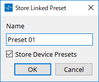
10.20. "Store Linked Preset" dialog box
In the "Linked Presets Manager" window, click the [Store] button to access this.
-
[Name] text box
Enter a name for the linked preset. By default, this will be "Preset + preset number." You can’t store if the linked preset name field is empty. -
[Store Device Presets] check box
If this check box is cleared, the check box in the list at the right of the "Linked Presets Manager" window is cleared, and the device’s preset will not be overwrite-stored.
If you previously stored settings in the device’s preset number, clear this check box to prevent overwriting. The settings are stored with the [Store] check box cleared. -
[OK] button
Specifies the linked preset and closes the dialog box. -
[Cancel] button
Closes the dialog box without specifying the linked preset.
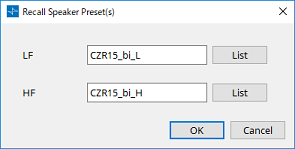
10.21. "Recall Speaker Preset(s)" dialog box
Here you can change the speaker library.
This dialog box appears when you right-click a speaker that is connected to a PC-series device and choose [Recall Speaker Preset(s)].
-
Library
For each connector, indicates the library item that is specified. Immediately after the dialog box appears, the default library item is shown. -
[LIST] button
Selects and shows library items. -
[OK] button
Specifies a library item and closes the dialog box. -
[Cancel] button
Closes the dialog box without specifying a library item.