PC-series power amps
13. PC-series power amps
When you open the device sheet for a PC-series device, the "Presets" area, the device sheet, and the "Bird’s Eye view" appear.
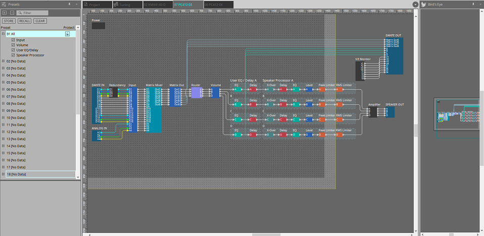
When you double-click a component in the device sheet, the component editor opens.
13.1. "Presets" area
In this area you can store the settings of multiple parameters as a preset, or recall a stored preset to apply its parameters to the current settings. The parameters of the preset that is applied are called the "current parameters."
If you want to recall presets for multiple units simultaneously, click the
 button, and make settings in the
"Linked Presets Manager" window
.
button, and make settings in the
"Linked Presets Manager" window
.
-
[STORE] button
This button stores a preset. If you select a preset in which settings have not been stored, the "Store Preset" dialog box appears. -
[RECALL] button
This button recalls a preset. -
[CLEAR] button
This button clears a preset. -
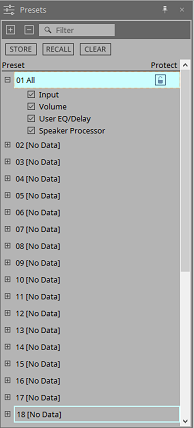
Preset list
This displays a list of the presets. Up to 32 presets can be stored.-
"Preset"
Shows the preset number and name. You can expand this and select the parameters that will be recalled.
If you select a stored preset and double-click this area, you’ll be able to edit the name.
Empty presets are shown with the name [No Data]. -
"Protect"
If you click the lock icon ( ), the icon changes to
 , protecting the preset so that it cannot be edited or cleared.
If you click the icon in the protected state, protection is removed.
-
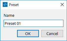
13.1.1. "Store Preset" dialog box
-
[Name]
Input the name of the preset. By default, this will be "Preset + preset number." You cannot enter a blank preset name. -
[OK] button
This stores the preset and closes the dialog box. -
[Cancel] button
This cancels the preset store operation, and closes the dialog box.
13.2. "Properties" area
Here we explain the dialog boxes related to the "Properties" area of the "Project" sheet.
An explanation of the item appears below when you click each Property.
Information such as the [Location] and [Device] for the [Display] is not saved as Style information.
For details on device settings, refer to the PC series owner’s manual.
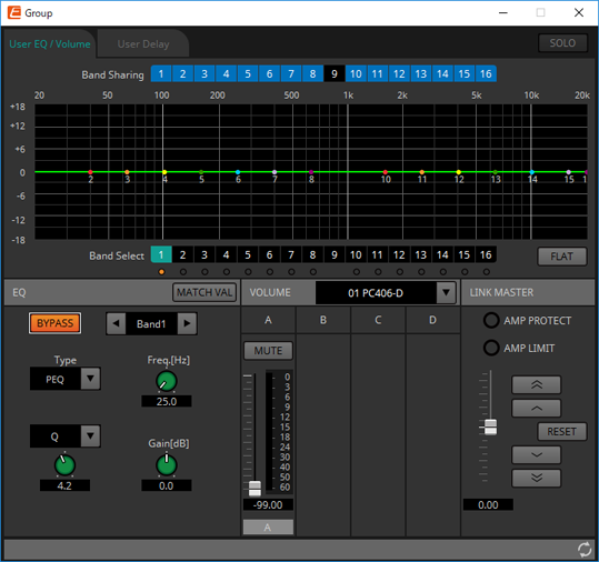
13.3. Link group editor
This appears when you double-click a link group on the "Tuning" sheet in which a channel of a PC-series unit is registered, or when you right-click and choose [Open Link Group Editor].
-
[SOLO] button
When online, this is enabled if the tool bar’s [Solo Mode] button is on.
If this is turned on, audio is output only from the channels that are registered to this link group, which is convenient when making final adjustments to the EQ, volume, and delay.
13.3.1. [User EQ/Volume] tab
Here you can make collective adjustments to the User EQ and volume of the channels registered in the group.
Use the Master fader to control the volume.
The "Volume" master fader collectively applies a relative adjustment to the volume of the channels registered in the group.
For details on EQ, refer to
"User EQ/User Delay" component editor
, and for Volume refer to
"Volume" component editor
.
-
[Band Sharing] buttons
If a channel is registered in multiple groups, click to select the bands owned by each group. An owned band is shown in blue. Bands that are not shown as white numbers on a black background are owned by other groups, and cannot be selected or operated.
Bands that you click and are colored blue are currently owned.
Ownership can be relinquished only by the link group editor that owns that band. -
[MATCHVAL] button
Copies the EQ settings of bands owned by the link group editor to the registered channels. -
LINK MASTER
Applies a relative adjustment to the volumes within the link group. -
[AMP PROTECT] indicator
This will light if the protection function of the PC unit itself is operating. -
[AMP LIMIT] indicator
This will light if the limiter of the PC unit itself is operating.-
Master fader
Applies a relative adjustment to the volumes within the link group. The adjustable range is shown above and below in gray.
When you right-click the fader and choose [Match Values], the members of the link group are set to the same volume value. -
 button
Raises the master fader by 3 dB. -
 button
Raises the master fader by 1 dB. -
[RESET] button
Moves the master fader to the 0 position. -
 button
Lowers the master fader by 1 dB. -
 button
Lowers the master fader by 3 dB.
-
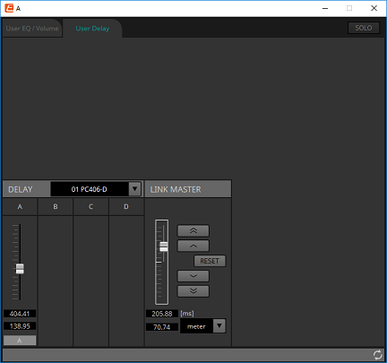
13.3.2. [User Delay] tab
Here you can collectively edit the User Delay of the "User EQ/User Delay" component editor for the linked jacks.
For details on delay, refer to
"User EQ/User Delay" component editor
.
-
LINK MASTER
Here you can apply a relative adjustment to the delay time of the channels of the devices that are registered in this link group.-
Master fader
Applies a relative adjustment to the delay times within the link group. The adjustable range is shown above and below in gray.
When you right-click the fader and choose [Match Values], the members of the link group are set to the same delay time value. -
button
Raises the master fader by 3 ms. -
button
Raises the master fader by 0.3 ms. -
[RESET] button
Moves the master fader to the 0 position. -
button
Lowers the master fader by 0.3 ms. -
button
Lowers the master fader by 3 ms. -
[ms]
Indicates the value of the master fader in ms units. -
[meter]/[feet] list box
Causes the display at left to show units of either meters or feet.
This also switches the display for individual jacks.
-
13.4. Alert list
The alerts generated by PC-series units, and their significance and the appropriate actions, are listed below.
A single alert is shown when the event occurs. A continuing alert is shown when the event occurs and when it ends.
If the problem is not solved, please contact a Yamaha service center listed at the end of the device’s operating manual.
| Number | Message | Severity | Content | Action | Single/Continuing |
|---|---|---|---|---|---|
|
05 |
Amplifier Output Muting |
Error |
The protection function operated to mute the amp output. |
Take action to clear the protection function that was the cause.
|
Continuing |
|
12 |
Mains Voltage Over 276[V] |
Error |
(at startup) The amp cannot start up because the power supply voltage exceeded the allowable operating voltage. |
Connect a stable power supply that is within the power supply requirements. |
Single |
|
The amp stopped because the power supply voltage exceeded the allowable operating voltage. |
Continuing |
||||
|
13 |
Power Supply Output Voltage |
Fault |
(at startup) The amp cannot start up because there is an abnormality in the output voltage of the power supply circuit. |
It might be that the unit has malfunctioned.
|
Single |
|
The amp was stopped because an abnormality occurred in the output voltage of the power supply circuit. |
Continuing |
||||
|
14 |
Power Supply Over-temperature |
Error |
(at startup) The amp cannot start up because the power supply circuit is too hot. |
- Lower the temperature before use.
|
Single |
|
The amp was stopped because the power supply circuit became abnormally hot. |
Continuing |
||||
|
21 |
Amplifier Ch.* DC Output |
Fault |
(at startup) The amp cannot start up because there is an abnormality in the amp output. |
It might be that the unit has malfunctioned.
|
Single |
|
The amp was stopped because there is an abnormality in the amp output of the corresponding channel. |
Continuing |
||||
|
22 |
Amplifier Ch.* Overcurrent |
Error |
The output was muted because excessive current flowed to the amp of the corresponding channel. |
- Reduce the output volume so that the current value does not become excessive.
|
Continuing |
|
23 |
Amplifier Ch.* Overtemp Level 1 |
Error |
Because the amp temperature of the corresponding channel exceeded level 1, the fan rotation speed was raised and the limiter was applied to the output. |
- Reduce the output volume so that the temperature does not become excessive.
|
Continuing |
|
24 |
Amplifier Ch.* Overtemp Level 2 |
Error |
Because the amp temperature of the corresponding channel exceeded level 2, the fan rotation speed was raised and the limiter was applied to the output. |
Continuing |
|
|
25 |
Amplifier Ch.* Overtemp Level 3 |
Error |
Because the amp temperature of the corresponding channel exceeded level 3, the fan rotation speed was raised to the maximum and the output was muted. |
Continuing |
|
|
26 |
Ch.* High Load |
Warning |
The impedance value of the corresponding channel monitored by the Load Monitoring function is higher than the specified value. |
- Check that there is no abnormality in the speaker or cable.
|
Continuing |
|
27 |
Ch.* Low Load |
Warning |
The impedance value of the corresponding channel monitored by the Load Monitoring function is lower than the specified value. |
Continuing |
|
|
31 |
Fan * Error |
Fault |
The fan of the corresponding number has stopped rotating. |
It might be that the unit has malfunctioned.
|
Continuing |
|
42 |
Input D* Change To 2nd |
Warning |
The Input Redundancy Backup function has switched the audio to the second priority circuit. |
Check whether the main audio circuit (Dante) has malfunctioned.
|
Single |
|
43 |
Input D* Change To 3rd |
Warning |
The Input Redundancy Backup function has switched the audio to the third priority circuit. |
Check whether the main or the second priority audio circuit (Dante) has malfunctioned.
|
Single |
|
61 |
Dante Module Failed |
Fault |
The internal Dante module is not working correctly. |
It might be that the unit has malfunctioned.
|
Continuing |
|
63 |
Firmware Versions Mismatch |
Error |
The version of this unit’s firmware is not compatible with the version of the Dante firmware. |
The updater provided on the web contains the firmware for this unit and the Dante firmware as a set. Update both. |
Single |
|
64 |
Dante Is Not Working By Giga Bit |
Error |
A device that does not support gigabit Ethernet is connected.
|
If you want to transmit audio via Dante, use devices that support gigabit Ethernet. |
Continuing |
|
65 |
Dante Is Working At Secondary |
Warning |
In Redundant mode, Dante audio communication is occurring on the Secondary circuit.
|
Check whether the primary circuit may have malfunctioned. |
Continuing |
|
66 |
Error Occurred At Secondary Port |
Warning |
In Redundant mode, the Dante Primary circuit is operating correctly, but the Secondary circuit is not connected.
|
If connection of the Secondary circuit is needed, check whether it may have malfunctioned. |
Continuing |
|
67 |
Wrong Word Clock |
Warning |
A problem was detected in the word clock. |
- In Dante Controller, correctly set the word clock of the entire system.
|
Continuing |
|
69 |
Dante Port Is Not Connected |
Warning |
In Redundant mode, the Dante Primary circuit is operating correctly, but the Secondary circuit is not connected.
|
Make sure that the Dante circuit is correctly connected. |
Continuing |