PC-series power amp component editors
14. PC-series power amp component editors
When you double-click a component in the device sheet, the component editor opens.
Here we explain the component editors for the PC series and the dialog boxes and windows that are closely related to the components.
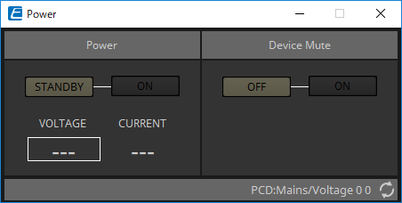
14.1. "Power" component editor
Switches the power of the device, and indicates the electrical current value of the unit.
This is available only when online.
-
Power
-
[STANDBY]/[ON] buttons
Switch the power between standby/on. -
[VOLTAGE]
Indicates the voltage value of the power supply input. -
[CURRENT]
Indicates the electrical current value of the device.
-
-
Device Mute [OFF]/[ON] buttons
Switch the device’s Device Mute on/off.
If this is on, the speaker output is muted for all channels of the amp.
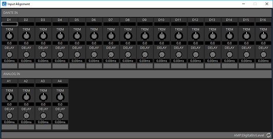
14.2. "Input Alignment" component editor
This appears when you double-click the "DANTE IN" component or the "ANALOG IN" component.
Here you can make settings for the input jacks, and view the levels of the audio signals that are being input.
-
Input level
Indicates the level after it is compensated by TRIM and DELAY. -
[TRIM] knob
Compensates for level differences between input jacks. -
[DELAY] knob
Compensates for latency differences between input jacks. -
Channel name
Shows or edits the input jack name.
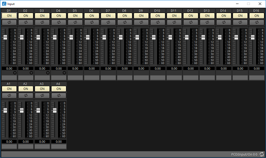
14.3. "Input" component editor
-
[ON] button
Switches the input of each channel between enabled and disabled. -
[φ] button
Inverts the phase of each channel’s input signal. -
Fader
Adjusts each channel’s input level. You can right-click the fader to access the context menu, and select [0 dB] or [-Infinity]. -
Redundancy indicator
Lit when the channel is redundant. This is lit yellow if the channel is switched to 2nd, and lit red if switched to 3rd. -
Channel name
Shows or edits the channel name.
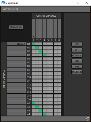
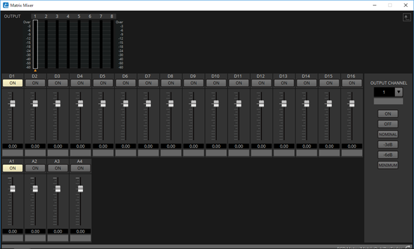
14.4. "Matrix Mixer" component editor
This is a mixer that allows input signals to be freely routed to output channels.
-
[SEND LEVEL] button
Opens the "Matrix Mixer" parameter edit window, allowing you to edit settings such as the send level to each output channel. -
[INPUT CHANNEL]
Indicates the input channels. The input channel name area lets you view and edit the name. -
[OUTPUT CHANNEL]
Indicates the output channels. The output channel name area lets you view and edit the name. -
Channel matrix
Shows the send level and delay of each channel. The horizontal axis indicates the input channel, and the vertical axis indicates the output channel. Click here to turn send on/off.
You can right-click a cross-point and choose [Open Parameter Window] (open the "Matrix Mixer" parameter setting window), [Out ON] (turn on the entire vertical axis), [Out Off] (turn off the entire vertical axis), [In ON] (turn on the entire horizontal axis), or [In OFF] (turn off the entire horizontal axis).
You can also open the "Matrix Mixer" parameter setting window by double-clicking a cross-point.
When you double-click a channel name display area located above or to the left of the matrix, a dialog box opens, allowing you to edit the name of the channel. -
[ON] button
Turns all on. -
[OFF] button
Turns all off. -
[NOMINAL] button
Sets all send levels of the matrix to 0 dB. -
[-3dB] button
Sets all send levels of the matrix to -3 dB. -
[-6dB] button
Sets all send levels of the matrix to -6 dB. -
[MINIMUM] button
Sets all send levels of the matrix to -∞ dB.
14.4.1. "Matrix Mixer" parameter setting window
Here you can adjust settings such as the send level to the output channels.
-
Meter
This displays the signal level of each output channel. The ▲ symbol indicates the currently selected output channel. -
[ON] button
Switches the send on/off. -
Fader
Adjusts the send level from the input channel. You can right-click the fader to access a context menu, and choose [0dB], [-3dB], [-6dB], or [-Infinity]. -
Channel name
Shows or edits the name of the input channel. -
[OUTPUT CHANNEL] list box
Selects the output channel. -
[OUTPUT CHANNEL] channel name
Shows or edits the name of the output channel. -
OUTPUT CHANNEL [ON] button
Turns all on. -
OUTPUT CHANNEL [OFF] button
Turns all off. -
OUTPUT CHANNEL [NOMINAL] button
Sets all send levels of the matrix to 0 dB. -
OUTPUT CHANNEL [-3 dB] button
Sets all send levels of the matrix to -3 dB. -
OUTPUT CHANNEL [-6 dB] button
Sets all send levels of the matrix to -6 dB. -
OUTPUT CHANNEL [MINIMUM] button
Sets all send levels of the matrix to -∞ dB.
14.5. "Matrix Out Level" component editor
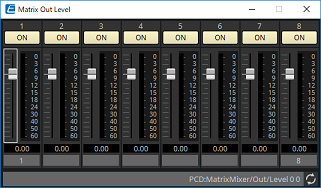
-
[ON] button
Switches the matrix out on/off. -
Fader
Adjusts the matrix out level.
You can right-click a fader knob and set the level by selecting [0 dB] or [-Infinity]. -
Channel name
Shows and edits the name of the matrix out channel.
14.6. "Router" component editor
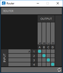
-
[INPUT]
Indicates the input channels. The input channel name area lets you view and edit the name. -
[OUTPUT]
Shows the output channels corresponding to each channel of the amp. The output channel name area lets you view and edit the name. -
Router
This is a router that distributes the signals. Click a square in the grid to switch the output on/off.
One input cannot be distributed to multiple outputs.
14.7. "Volume" component editor
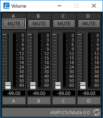
-
[MUTE] button
Switches mute on/off for the output channel. -
Volume fader
Sets the output volume to the speaker.
You can right-click a fader knob and set the volume by selecting [0 dB] or [-99 dB]. -
Channel name
Shows or edits the name of the input channel.
| The channel name is linked with the device’s jack → Properties → Label. |
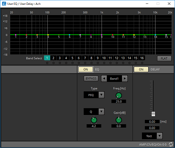
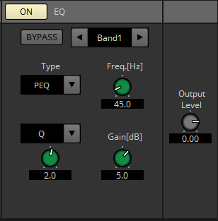
14.8. "User EQ/User Delay" component editor
-
EQ graph
Shows a graph of the EQ effect.
You can drag a control point to edit the parameters. -
[Band Select] buttons
If a button is selected, the current value is shown in "EQ," below. For bands whose "EQ" [BYPASS] button is on, the indicator below that [Band Select] button is lit. -
[FLAT] button
Sets the "EQ" [GAIN] to 0. -
"EQ"
Lets you make EQ-related settings.-
EQ [ON] button
Turns the EQ on/off. -
[BYPASS] button
Bypasses the band. -
Band slide banner
Selects the band for which to make EQ settings. -
[Type] list box
Selects the band type.
The frequency response is shown by the graph.-
PEQ (Parametric Equalizer)
Boosts or cuts the volume in the region of the specified frequency for the width specified by the Q setting. -
L.SHELF (Low Shelf)
Boosts or cuts the volume of the entire low-frequency region below the specified frequency. Use this for purposes such as bass boost.
[6dB/Oct] and [12dB/Oct] specify the amount of attenuation per octave. -
H.SHELF (High Shelf)
Boosts or cuts the volume of the entire high-frequency region above the specified frequency. Use this for purposes such as high boost.
[6dB/Oct] and [12dB/Oct] specify the amount of attenuation per octave. -
HPF (High Pass Filter)
Cuts the region below the specified frequency.
Specifies 12 dB/Oct as the amount of attenuation. -
LPF (Low Pass Filter)
Cuts the region above the specified frequency.
Specifies 12 dB/Oct as the amount of attenuation.
-
-
[Freq.[Hz]] knob
Specifies the frequency of each frequency band. -
[Gain[dB]] knob
Specifies the amount of boost or cut that will be applied to the frequency.
-
-
Delay
Here you can make delay-related settings.-
DELAY [ON] button
Turns delay on/off. -
Delay Time slider
Specifies the delay time.
-
-
Type list box
Selects the units in which to show the distance corresponding to the delay time specified by the Delay Time knob.
[meter]: Meters
[feet]: Feet
14.9. "Speaker Processor" component editor
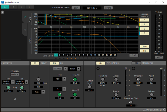
Library
information
Shows library information when a speaker library item with an FIR filter is recalled.
-
Channel switching tabs
Switch between the channels whose settings you want to edit.
Pre-installed LIBRARY

-
[LIST] button
Selects and shows library items. -
[STORE] button
Saves the settings of the selected jack as a library item [.splp]).
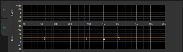
[SP] tab
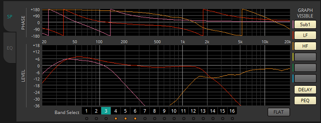
-
"PHASE"
Displays a crossover phase response curve. This display takes into account the response of the PEQ and the Delay.
Each jack is shown using a separate color. -
"LEVEL"
Displays a crossover amplitude response curve. This display takes into account the response of the PEQ and the Output Level.
Each jack is shown using a separate color. -
[Band Select] buttons
If a button is selected, the current value is shown in "EQ," below. For bands whose [BYPASS] button is on, the indicator below that [Band Select] button is lit. -
[FLAT] button
Sets the "EQ" [GAIN] to 0. -
[GRAPH VISIBLE] buttons
Switch the graph of each channel between visible and hidden. -
[DELAY] button
Shows or hides the effect of the delay response in the crossover curve that is displayed. -
[PEQ] button
Shows or hides the effect of the PEQ response in the crossover curve that is displayed.
[EQ] tab
-
"PHASE"
Displays the EQ phase response curve. -
"LEVEL"
Displays the EQ amplitude response curve.
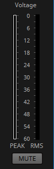
"Voltage"
-
Meter
Shows the output voltage of each channel.
PEAK and RMS are shown. -
[MUTE] button
If this is on, the output is muted, and its crossover graph is shown as a dotted line.
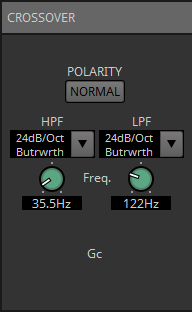
"CROSSOVER"
-
[POLARITY] button
Inverts the phase of the signal that is output from each output channel. Switch between NORMAL/INVERTED. -
[HPF]/[LPF] type list box
Specifies the amount of attenuation and the filter type. A menu will appear when you click the list box. You can combine six slopes with four filter types.
[6dB/Oct], [12dB/Oct], [18dB/Oct], [24dB/Oct], [36dB/Oct], and [48dB/Oct] specify the amount of attenuation per octave. Lower values apply more gentle attenuation; higher values apply steeper attenuation.-
Thru
No filter will be applied. There will be no attenuation; the response will be the same at all frequencies. -
AdjustGc (Adjustable Gc)
Adjusts the Gc (gain at the cutoff frequency) in a range of –6–+6dB. Setting this to –3 dB will produce a Butterworth filter, and setting this to -6 dB will produce a Linkwitz-Riley filter. The Gc knob will appear when you select this. -
Butrwrth (Butterworth)
This is the most common response. The passed region is flat, and the gain at the cutoff frequency is -3 dB. -
Bessel
This curve emphasizes the phase response; the attenuation is more gradual than Butterworth, but the waveform will not be distorted when a square wave is passed through it. -
Linkwitz (Linkwitz-Riley)
The order of this filter will be a power of two; the summed voltage of the LPF and HPF outputs will produce a gain of 0 dB across the entire frequency range. The passed region is flat, and the gain at the cutoff frequency is -6 dB.
-
-
HPF/LPF [Freq.] knobs
Specify the cutoff frequency of the HPF/LPF. -
HPF/LPF [Gc] knobs (shown only if filter type is set to [AdjustGc])
Specify the gain at the cutoff frequency.
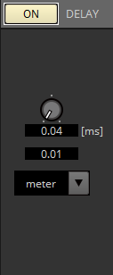
"DELAY"
-
DELAY [ON] button
Turns delay on/off. -
Delay Time knob
Specifies the delay time. -
Type list box
Selects the units in which to show the distance corresponding to the delay time specified by the Delay Time knob.
[meter]: Meters
[feet]: Feet
"EQ"
-
EQ [ON] button
Turns the EQ on/off. -
[BYPASS] button
Bypasses the band. -
Band slide banner
Selects the band for which to make EQ settings. -
[Type] list box
Selects the band type.
The frequency response is shown by the graph.-
PEQ (Parametric Equalizer)
Boosts or cuts the volume in the region of the specified frequency for the width specified by the Q setting. -
L.SHELF (Low Shelf)
Boosts or cuts the volume of the entire low-frequency region below the specified frequency. Use this for purposes such as bass boost.
[6dB/Oct] and [12dB/Oct] specify the amount of attenuation per octave. -
H.SHELF (High Shelf)
Boosts or cuts the volume of the entire high-frequency region above the specified frequency. Use this for purposes such as high boost.
[6dB/Oct] and [12dB/Oct] specify the amount of attenuation per octave. -
HPF (High Pass Filter)
Cuts the region below the specified frequency.
Specifies 12 dB/Oct as the amount of attenuation. -
LPF (Low Pass Filter)
Cuts the region above the specified frequency.
Specifies 12 dB/Oct as the amount of attenuation. -
APF 1st/2nd (All Pass Filter)
Passes the signals of the entire frequency range, affecting only the phase. It is used to correct the phase of the crossover region.
APF 1st rotates the phase 0˚–180˚, and APF 2nd rotates the phase 0˚–360˚. APF 2nd allows you to set the Q. -
Horn EQ
A horn speaker is characterized by a high frequency level roll-off. Horn EQ compensates for this tendency.
-
-
[Freq.[Hz]] knob
Specifies the frequency of each frequency band. -
[Q]/[B/W] list box/knob
Use the list box to select the type of width for each frequency band, and use the knob to specify the width. For [B/W], the setting is in Octave units. -
[Gain[dB]] knob
Specifies the amount of boost or cut that will be applied to the frequency. -
[Output Level] knob
Specifies the output level of each jack. This is reflected in the "LEVEL" graph of the [SP] tab.
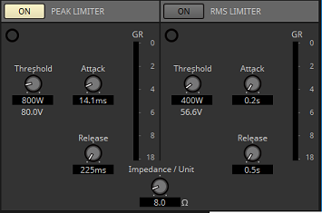
"PEAK LIMITER"/"RMS LIMITER"
This is not shown if the corresponding jack is set as a high-impedance connection such as 70V or 100V.
-
[ON] button
Turns the limiter on/off. If the button is off, the limiter will be bypassed. -
Gain Reduction indicator
This will light when the threshold value is exceeded. -
[Threshold] knob
This specifies the threshold value at which the limiter applies, in terms of output power (W). -
[Attack] knob
Specifies the speed at which the limiter will take effect. -
[Release] knob
Specifies the speed at which the limiter will release. -
"GR" meter
Indicates the amount of gain reduction. -
[Impedance / Unit] knob
Specifies the nominal impedance of the speaker.
Even when connecting multiple speakers in parallel, specify this as the impedance of one unit.
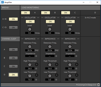
14.10. "Amplifier" component editor
-
BRIDGE [ON] button
If this is enabled, the amp will be in BRIDGE output mode.
In BRIDGE mode, adjacent odd-numbered and even-numbered channels are bridge-connected to operate as a high-power amp. -
CHANNEL SLEEP [ON] button
If this is enabled, the amp of that channel will sleep. By putting unused channels to sleep, you can conserve electrical power and reduce excessively high temperatures.
This is different than the Auto Sleep setting in the "Properties" area of the "Project" sheet. -
"LOAD MONITORING"
Here you can make settings for monitoring the speaker output impedance in order to determine whether the output has been interrupted by an electrical short, breakage, or speaker malfunction. By outputting a pilot tone, the impedance can be detected in a stable manner without relying on the audio signal output.
This is not shown for channels that are specified as a Hi-Z connection.-
[ON] button
Switches LOAD MONITORING on/off. -
OSCILLATOR [ON] button
Specifies whether a pilot tone is output.
A pilot tone from an external input can also be used to detect the impedance. -
OSCILLATOR [Level] knob
Specifies the output level of the pilot tone. -
IMPEDANCE [Detection Freq.] knob
Specifies the frequency for which impedance is detected. The [Impedance] field below shows the measured impedance. -
IMPEDANCE [High Threshold] knob/indicator
Specifies the upper threshold of impedance that is measured. If the specified value is exceeded, it is determined that the speaker has malfunctioned, and the indicator will light.
If the specified value is exceeded, it might be that the connection is open, such as due to a broken cable. -
IMPEDANCE [Low Threshold] knob/indicator
Specifies the lower threshold of impedance that is measured. If the measurement drops below the specified value, it is determined that the speaker has malfunctioned, and the indicator will light.
If the measurement drops below the specified value, it might be that the resistance has dropped due to a shorted coil, etc.
-
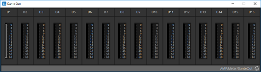
14.11. "Dante Out" component editor
This shows the signal level that is output via Dante.
-
Meter
This shows the signal level that is output via Dante.
| The speaker jack’s output voltage and output current are also output as the audio signal. You can calculate the impedance to detect a speaker fault, or check whether dropouts occur. This is also output from channels D9–D16 as an audio signal. |
14.12. "Speaker Out" component editor
This shows the speaker output jack’s output voltage and output current.
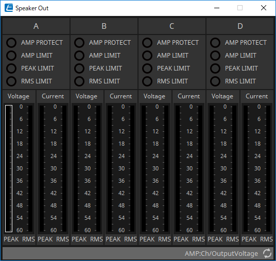
-
[AMP PROTECT] indicator
This will light if the protection function of the PC unit itself is operating. -
[AMP LIMIT] indicator
This will light if the limiter of the PC unit itself is operating. -
[PEAK LIMIT] indicator
This is lit if the peak limiter within the speaker processor of the PC unit is operating. -
[RMS LIMIT] indicator
This is lit if the RMS limiter within the speaker processor of the PC unit is operating. -
[Voltage] meter
Shows the output voltage as Peak and RMS. -
[Current] meter
Shows the output current as Peak and RMS.