

Front side
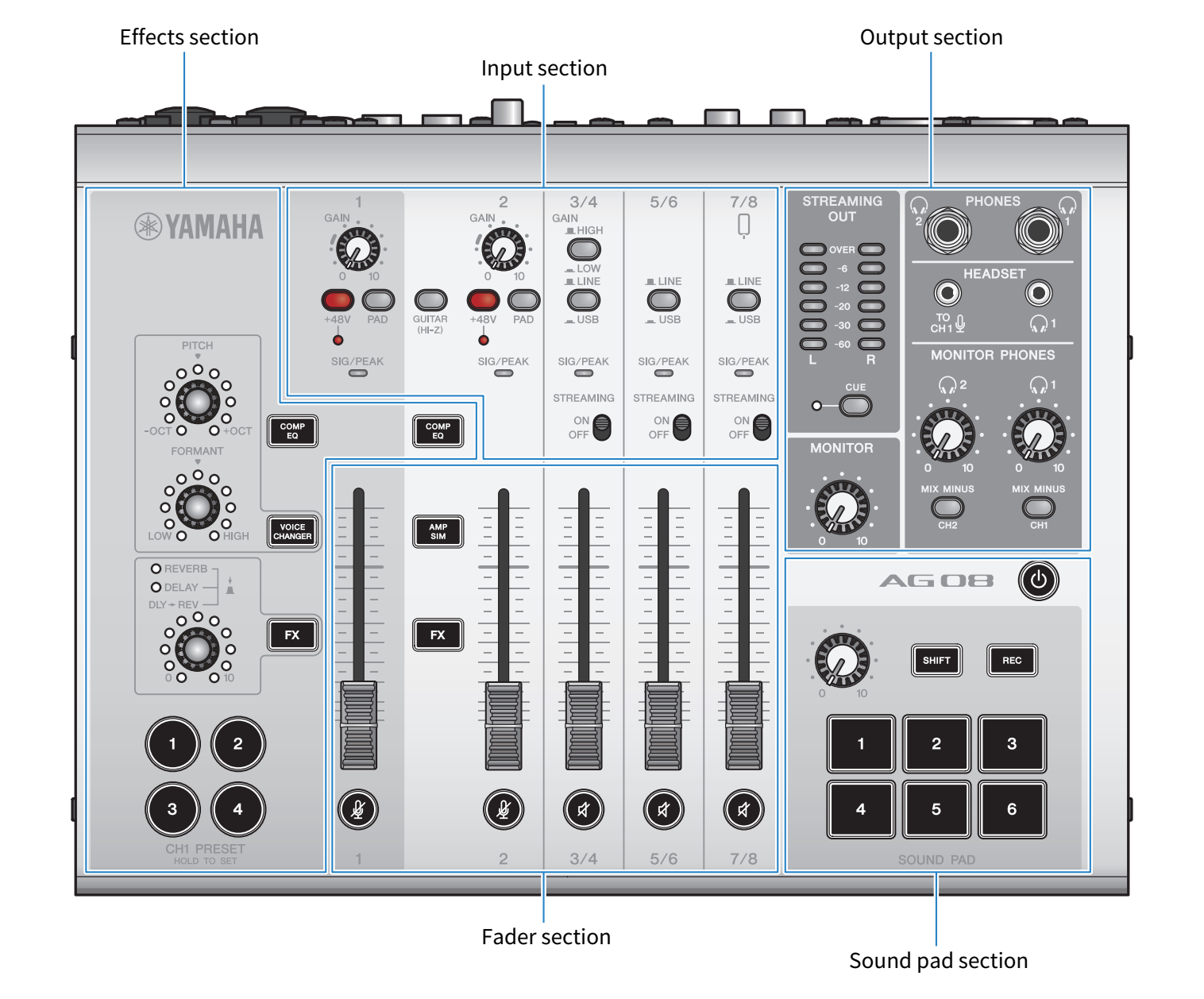
Top panel input section
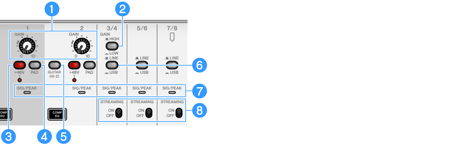
a | [GAIN] knobs Determines the base volume for the respective channel. Adjust the knobs so that the [SIG/PEAK] LED lights up red only briefly when you sing loudly or play strongly. |
b | [GAIN HIGH/LOW] selector switch Determines the base volume for channels 3/4. Set this to LOW (O) if the [SIG/PEAK] LED keeps lighting up red or if the sound is distorting. |
- Turn the channel faders to the minimum setting before you toggle the [GAIN HIGH/LOW] selector switch. This is because you may hear a noise when the switch is toggled.
c | Phantom [+48V] switch/[+48V] LED When this switch is turned on (O), the [+48V] LED lights, and DC +48V phantom power is supplied to the XLR plug connected to the mic/line input connectors for channels 1 and 2. Turn this switch on when you are using a condenser mic. |
- Turn the switch off if you don’t need phantom power.
- To prevent this product or your external device from malfunctioning and to prevent noise, turn this switch off before connecting a device that does not support phantom power to channels 1 or 2.
- To prevent this product or your external device from malfunctioning and to prevent noise, do not unplug or insert a cable into channel 1 or 2 while the switch is still on.
- To prevent this product or your external device from malfunctioning and to prevent noise, turn phantom power on/off only when the channel 1/2 faders are at minimum setting.
d | [PAD] switch These switches attenuate the input signal level. Turn these switches on if the input audio sounds distorted or if it seems too loud. |
e | [GUITAR (HI-Z)] switch Use this switch to change the input impedance for channel 2, either on (O) or off (N). Set this to on when directly connecting an instrument with high output impedance like an electric guitar or bass guitar to channel 2. If you will use the “on” setting for this switch, connect your instrument to this product with an unbalanced phone connector. The product will not work correctly if you use a balanced cable. |

- Set the output controls such as the [MONITOR] knob and the [MONITOR PHONES] [H] knob to their minimum setting before toggling this switch. This is because the levels may suddenly get loud, which could damage your hearing or cause external devices to malfunction.
f | [LINE/USB] selector switches These switches toggle between the audio source from the analog input connectors of channels 3/4, 5/6 and 7/8 and the input audio from the USB port. For details on what happens when this is switched to USB, see “Settings on the computer” in “Connecting to your computer and configuring the settings (Windows)” or “Settings on the computer” in “Connecting to your computer and configuring the settings (Mac)”. |
- Adjust the volume before you toggle these switches. This is because the levels may suddenly get loud depending on the device you’ve connected, which could damage your hearing or cause external devices to malfunction.
g | [SIG/PEAK] LED Use these indicators to check the input signal levels. To send audio at an appropriate volume to your computer, adjust the levels for each channel so that the green LEDs light up but the red LEDs only briefly light up when a loud sound is input. |
h | [STREAMING ON/OFF] switch These switches toggle the output to the livestream bus (STREAMING bus) of the input from channels 3/4, 5/6 and 7/8. |
Fader section
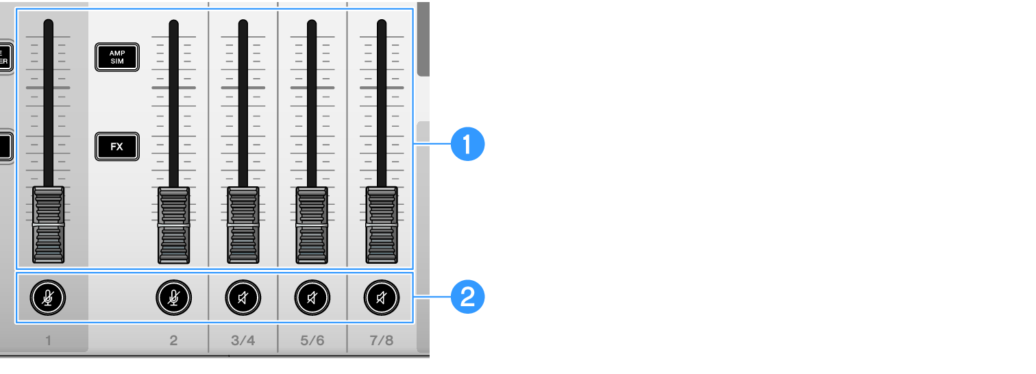
a | Channel faders Adjusts the output level of the audio input from channels 1–8. |
b | (m) (s) Mute buttons Toggles the mute feature on (the LED lights up red) or off (the LED goes dark). You can use this to silence the sound when you take a short break or in similar situations while livestreaming. |
Effects section
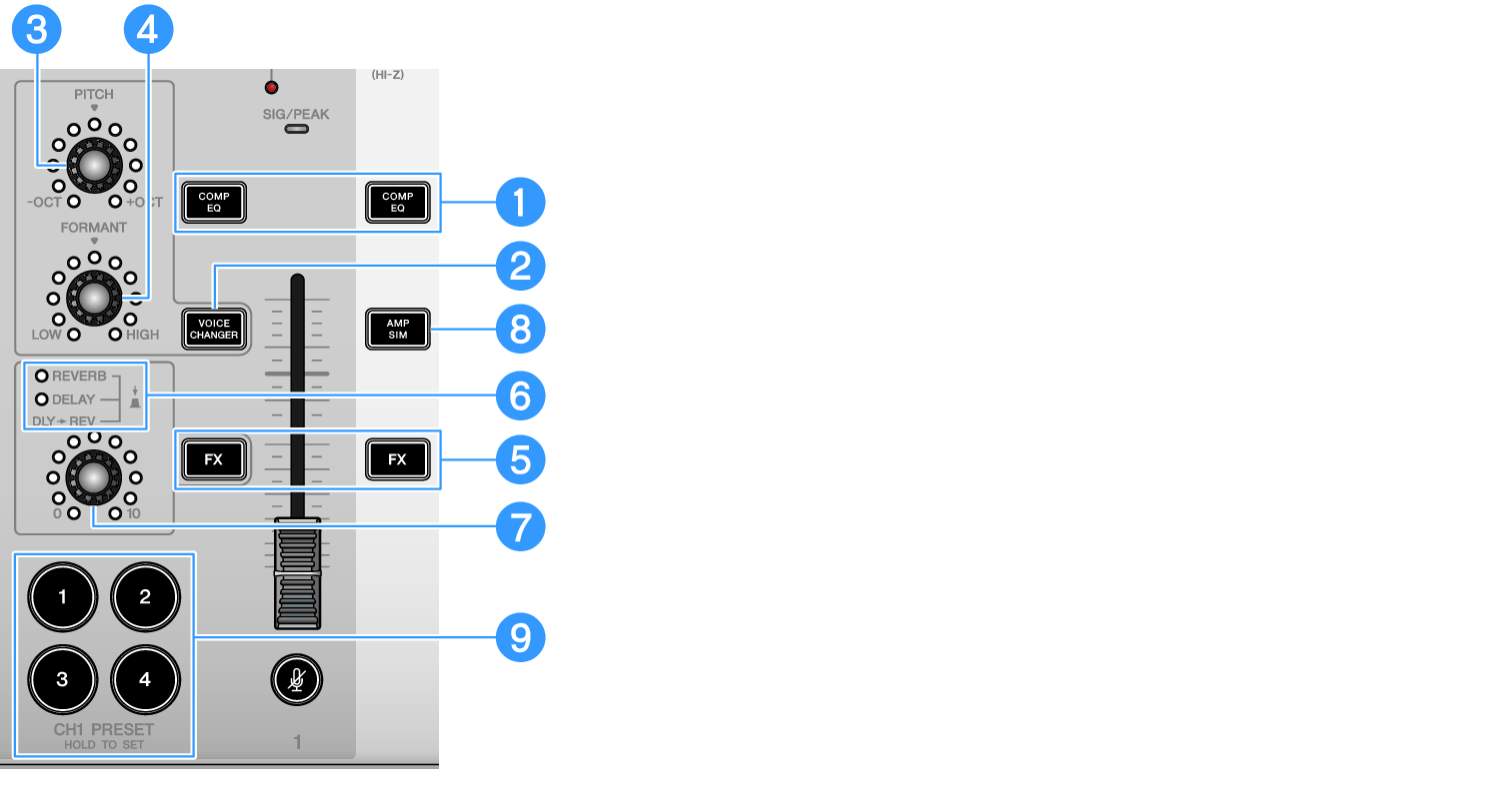
a | [COMP EQ] buttons These buttons toggle the gate/compressor/equalizer on or off for channels 1 and 2. This is set at the optimal setting for livestreaming by default. This keeps down unnecessary noise in the low end and helps smooth out differences in the input levels. |
b | [VOICE CHANGER] button Toggles the voice changer function for channel 1 on/off. |
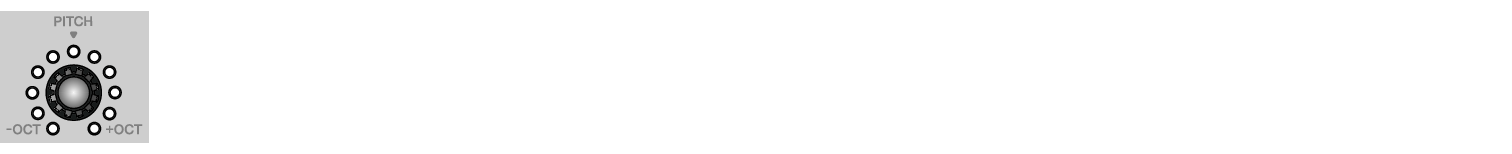
c | [PITCH] knob Turn this knob to adjust the pitch for the channel 1 voice. You can change the pitch within a range of one octave up or down. When the parameter value is at zero, only the center LED lights up. |
d | [FORMANT] knob Turn this knob to adjust the formant for the channel 1 voice. Turn this towards LOW for a more masculine voice, and turn this towards HIGH for a more feminine voice. |
e | [FX] buttons Toggles the send on/off to FX 1 from channel 1 and to FX 2 from channel 2. |
f | FX TYPE ([REVERB]/[DELAY]/[DLY→REV]) LEDs Use these indicators to check the FX effect type for channel 1. When REVERB is selected, the REVERB indicator lights up; when DELAY is selected, the DELAY indicator lights up; and when DLY→REV (DELAY→REVERB) is selected, both indicators light up. |
g | FX SEND knobs Use these knobs to control the send level for FX1 of channel 1. Push these knobs to toggle the effect type for FX1 of channel 1. |
h | [AMP SIM] button Toggles the amp simulator function for channel 2 on/off. The amp simulator recreates the sound of playing an electric guitar through an amplifier. This simulates the characteristic “distorted” amp sound that’s heard when you directly connect an electric guitar. |
i | [CH1 PRESET] [1]–[4] buttons Use these buttons to register effect combinations for channel 1 as a preset, and recall them later. The button lights up for the preset you recall. You can store four presets. With AG08 Controller, you can select from six different colors for the button LEDs. Use AG08 Controller to change the LED colors. See “Using the presets” for how to register the presets. |
Top panel output section
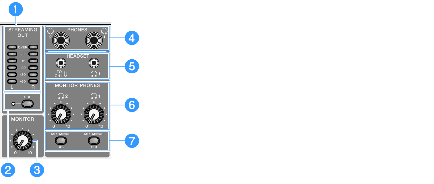
a | [STREAMING OUT] LED level meters These meters display the level of signal used for the streaming bus (STREAMING bus). Each horizontal meter lights up when its signal level (shown in the middle, in units of dB) is exceeded. When the signal level exceeds 0 dB, the OVER LED lights up red. |
b | [CUE] switch When this is turned on, the STREAMING OUT signal is output to both MONITOR PHONES 1 and 2, and the indicator to the left of the switch lights up. Turn this on when you want to check the streaming signal in headphones. |
c | [MONITOR] knob Adjusts the volume of audio sent to the device connected to the [MONITOR OUT] connectors. |
d | [PHONES 1 (H)/PHONES 2 (H)] connector (phone type) Connect your headphones here. Compatible with stereo phone plugs. When using headphones or earphones with a stereo mini-plug, you can also use the [HEADSET] headphones [H] output connector. |
e | [HEADSET] mic [ Connect a headset mic here. Normally, the plug is pink. The audio input from this connector is sent to channel 1. |
- When you connect a mic plug into the [HEADSET] mic [
 ] input connector, the audio from the device connected to the [CH1 MIC/LINE] connector is muted.
- Use AG08 Controller to set the gain for the signal input from the [HEADSET] mic [] input connector, instead of using the channel 1 [GAIN] knob on the top panel. Press the menu [
 ] button on the AG08 Controller app, and select Settings → HEADSET MIC Gain to configure the settings.
[HEADSET] headphones [H] output connector Connect the headset’s headphones here. Normally, the plug is light green. The audio that is output is the same as that of the headphones [H] output connector. |
f | [MONITOR PHONES 1 (H)/MONITOR PHONES 2 (H)] knobs These knobs adjust the volume for the headphones connected to the headphones [PHONES 1(H)/PHONES 2(H)] connectors or the [HEADSET] headphones [H] output connector. |
g | [MIX MINUS CH1/MIX MINUS CH2] switch When this is turned on (O), the sound inputted to channels 1 and 2 is not output to the [PHONES 1(H)/PHONES 2(H)] connectors (monitoring OFF). Use this when you don’t want to hear your own voice during monitoring. For example, turn the [MIX MINUS] switch on when there is no need to hear your own voice or your own playing in headphones during a livestream or when recording. |
- You can use the AG08 Controller app to add channels that are not outputted during monitoring. Press the menu [] button on the AG08 Controller, and select Settings → MIX MINUS to make the settings.

Top panel sound pad section
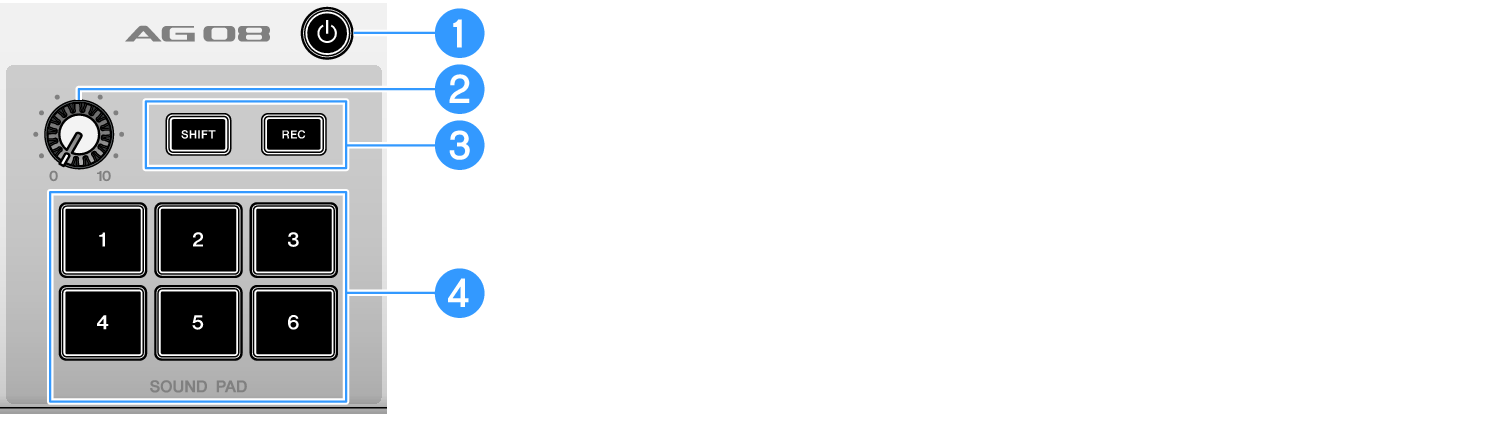
a | [z] (standby/on) switch Toggles between power standby and on. To set this to standby while the power is on, long-press the switch for at least two seconds. It takes about eight seconds to completely switch to standby. |
- Rapidly toggling this switch between standby and on may cause the product to malfunction. After you toggle the switch to standby, make sure to wait for at least six seconds before toggling the switch on again.
- The switch flashes when there is not enough power supplied from the computer.
b | Sound pad level knob Adjusts the output level of the audio from the sound pad. |
c | [SHIFT]/[REC] buttons Use the [SHIFT]/[REC] buttons in combination with the [SOUND PAD] buttons to record with the sound pad. See “Recording to the sound pad” for details. |
d | [SOUND PAD] [1]–[6] buttons These buttons play back/record audio files such as sound effects that you have previously registered. You can use these to record the sound pad data on this unit, or use the AG08 Controller app to import audio files. With AG08 Controller, you can select from six different colors for the button LEDs. Use AG08 Controller to change the LED colors. See “Using the sound pad” for how to register the sound pad data. |