Basic process
4. Basic process
Using the creation of a simple page as an example, this section explains the process from startup to controlling a device. In this example, we control the level and on/off for input channel 1 of a DM7 (console ID=1).
In the case of an MRX7-D/DME Series, this procedure cannot be used to place a widget; refer to
"Adding parameters and meters from apps other than ProVisionaire Control."
4.1. Start up, and register devices
Here’s how to start ProVisionaire Control, create a controller and page, and register a device to control.
-
Start ProVisionaire Control.
To start, choose [Start] button → [All Programs] or [All Apps] → [Yamaha ProVisionaire Control PLUS]→[ProVisioniare Control PLUS Vx.x] (x.x is the version number). -
If you want to create a new project, click [New Project] button
 .
.
If you want to load an existing file, choose the [File] menu command [Open Project File], and select the file that you want to load.
In this example, we explain the procedure when you click [New Project] button.
-
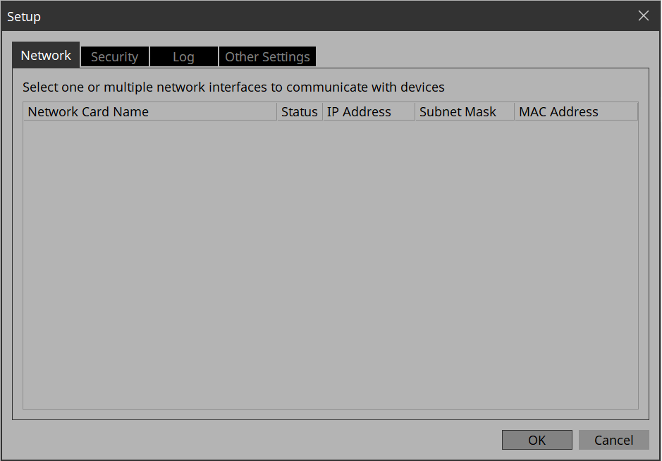
When the “Setup” dialog box appears, click [OK] or [Cancel].
ProVisionaire Control transitions to design mode, and the “New Project Wizard” dialog box opens.In the “Setup” dialog box, when you select a network adapter in “Network” and click [OK], the device will be recognized by connecting the computer on which ProVisionaire Control is installed to the network. Register a device by right-clicking on the relevant device in the “Devices” area and selecting [Add]. Up to eight network adapters can be selected at the same time.
-
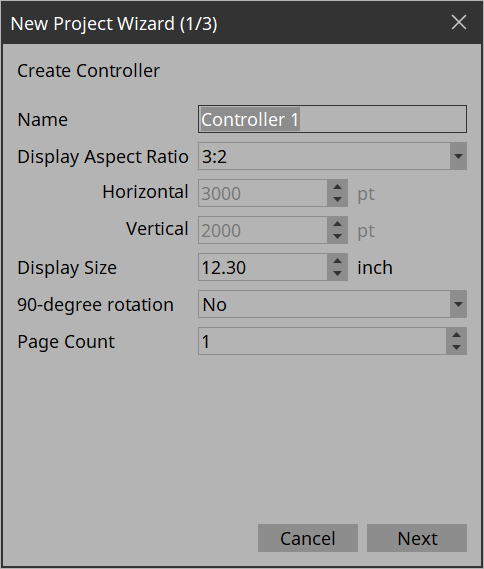
Configure the settings to match the terminal screen for operating the controller (the device where Kiosk will be installed), then click the [Next] button.
In this example, we keep the default settings.
All settings can be changed later in Properties under Controller.Tips
If you don’t know the aspect ratio of the screen, select [3:2] and place the widgets accordingly.
Once the aspect ratio has been finalized, reconfigure the screen size in Properties under Controller.
-
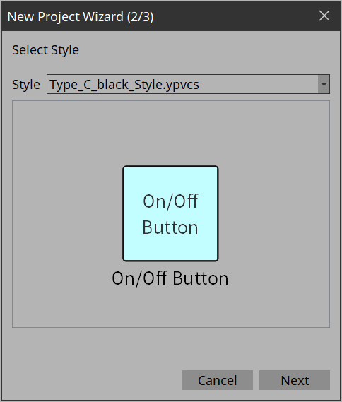
Select the Style file to be used when creating the controller and click the [Next] button.
-
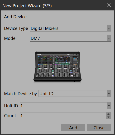
Make the following settings, and click the [Add & Close] button.
-
Match Device by
Unit ID: Matches the device by using the Unit ID/Device ID as a key.
IP Address: Matches the device by using the IP address as a key. -
Count
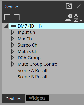
If “Match Device by” is set to “Unit ID”, you can register multiple devices at once. The devices are registered sequentially starting from the Unit ID.The DM7 whose Unit ID is 1 is added to the “Devices” area, and the dialog box closes.
To register other devices to control, click the [Add] button and add all the necessary devices.
4.2. Placing widgets on a page
Here’s how to place widgets in the work area so that the parameters of the DM7 can be controlled.
This section describes how to drag and drop widgets from the parameter list.
-
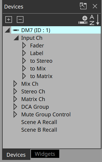
In the “Devices” area, in the “Device List,” click the triangle
 located at the left of DM7.
The parameter group is expanded.
-
Click the triangle
located at the left of the parameter group containing the parameter that you want to assign.
The parameters are expanded.
In this example, we want to control the level and on/off of input channel 1, so you’ll expand [Input Ch].
-
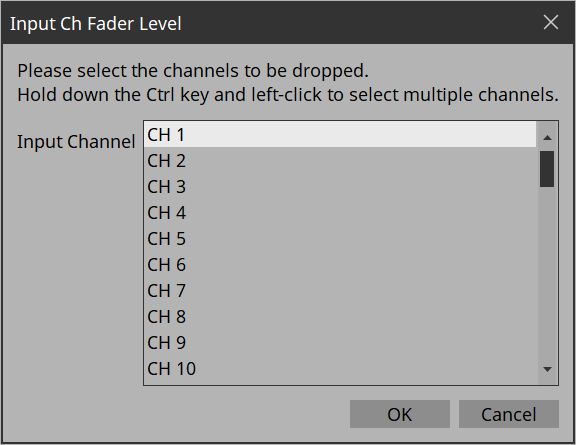
Drag and drop [Level] in the work area.
The “Input Ch Fader Level” dialog box opens.
Tips
By holding down the < Ctrl > key or < Shift > key while you make a selection, you can select multiple channels and place multiple sliders simultaneously.
Tips
When you drop a parameter onto a blank area in the work area, a default widget is placed.
If you drop a parameter onto an already placed widget, you can replace (or add, depending on the widget type) the parameter to be controlled.
-
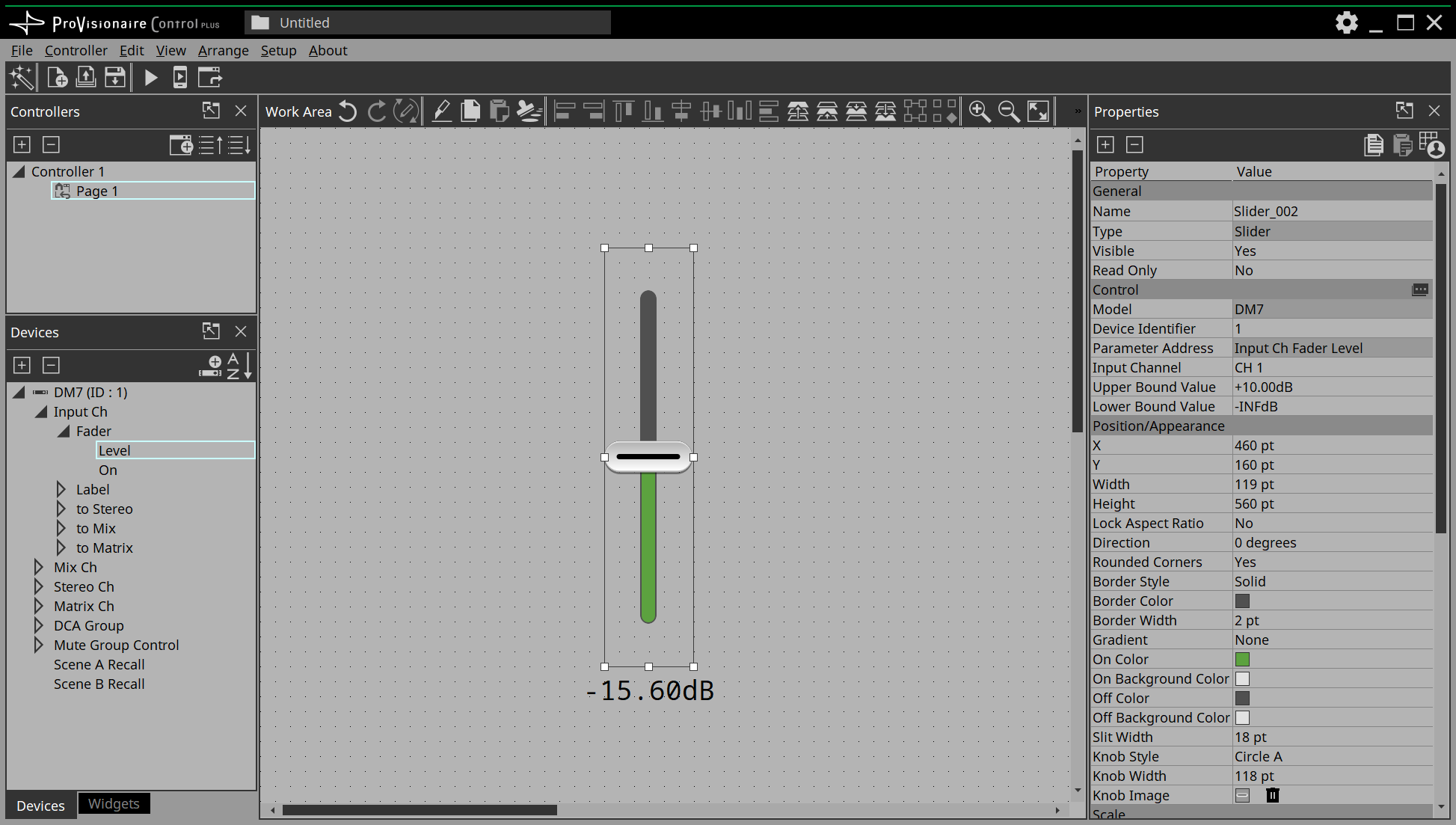
Select [CH1] and click the [OK] button.
The slider is placed in the work area.
-
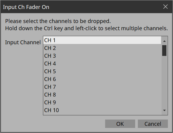
Drag and drop [On] into the work area.
The “Input Ch Fader On” dialog box opens.
-
Select [CH1] and click the [OK] button.
The button is placed in the work area.
-
Drag and drop the slider and button to place them as you like.
Tips
There are other ways to place widgets:
・Drag and drop a widget from the widget list displayed in ProVisionaire Control. Then, drag and drop a parameter onto the widget.
・Drag and drop a widget displayed in ProVisionaire Design or MTX-MRX Editor onto the page of ProVisionaire Control to place it.
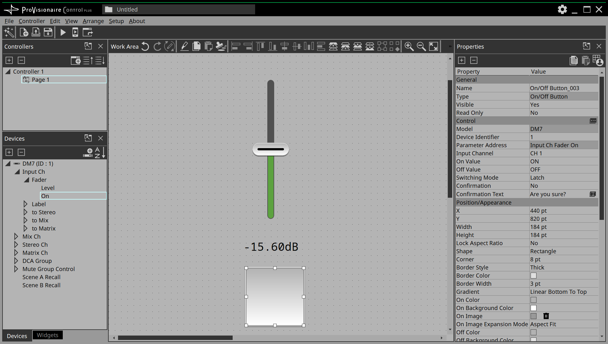
4.3. Labeling widgets for easier recognition
If you simply place a widget, Kiosk will not provide any indication as to what that widget does; here’s how to add a label that will be shown in Kiosk.
-
Click the slider.
The slider is selected. -
「In the “Properties” area’s “Label,” click the column at the right of “Text.”
The “Edit Text” dialog box opens. -
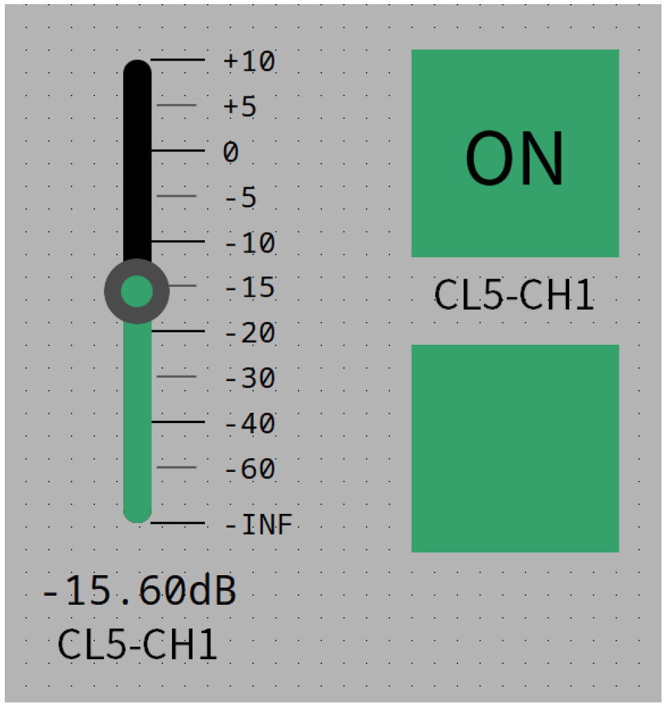
Enter a name for the slider.
For this example, specify “DM7-CH1.”

-
Click the [OK] button.
The input is confirmed, and the name is shown below the slider. -
In the same way, assign the label “DM7-CH1” to the button.
-
In the button’s “Properties” area, in “Text,” click the column at the right of “On Text.”
-
Enter the text for when the button is on.
For this example, specify “ON.” -
In the “Text” area, click the column at the right of “Off Text.”
-
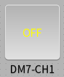
Enter the text for when the button is off.
For this example, specify “OFF.” -
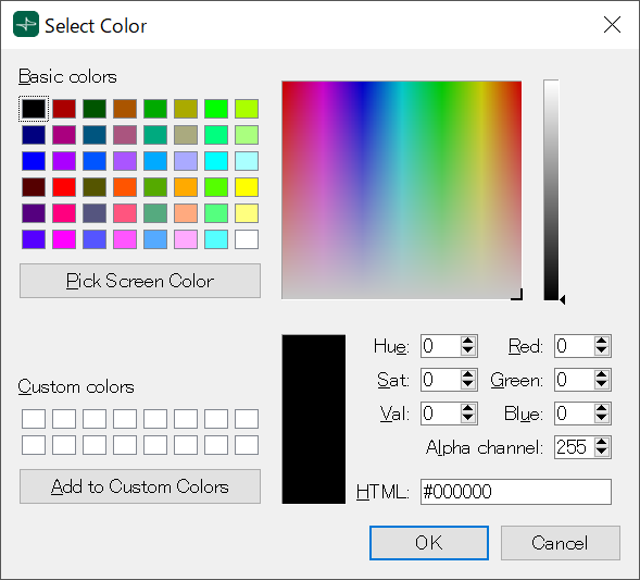
In the “Text” area, click the column at the right of “Off Color.”
The “Select Color” dialog box opens.
-
Select a different text color for when the button is off.
For this example, select yellow.
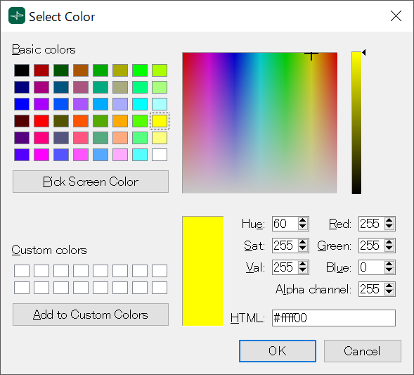
-
Click the [OK] button.
The dialog box closes, and the text color when off will be yellow.
-
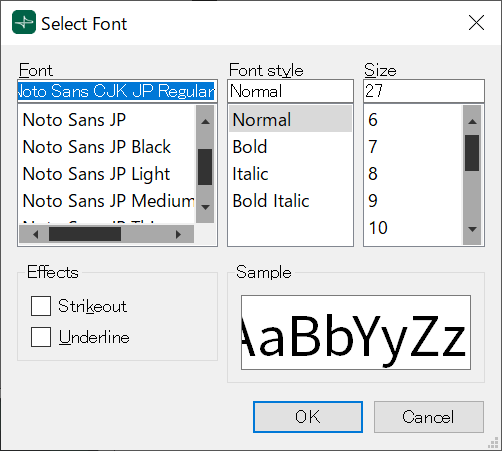
In the “Text” area, click the column at the right of “Font.”
The “Select Font” dialog box opens.
-
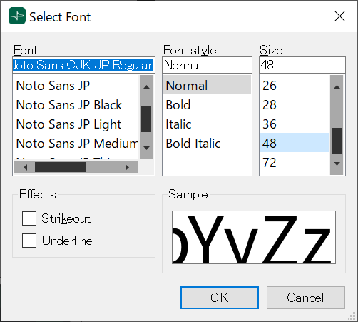
Adjust the font used for the text when the button is on/off.
For this example, set the font size at 48 points.
-
Click the [OK] button.
The dialog box closes, and the text size when the button is on/off will change.
4.4. Adding a page
Let’s add a page to the controller, and add buttons for switching between pages.
-
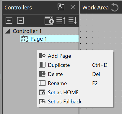
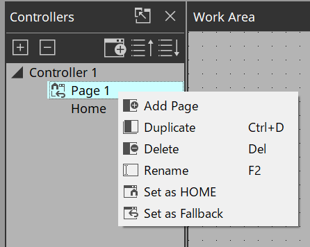
In the “Controllers” area, right-click any location.
The context menu appears.
-
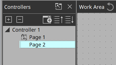
Select [Add Page].
A page is added to [Controller 1], and the work area switches to the page that was added.
-
Right-click the added page.
The context menu appears.
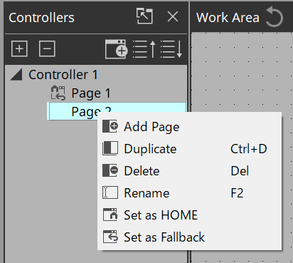
-
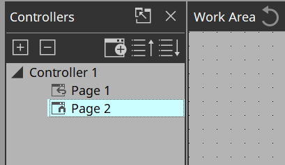
Select [Set as HOME].
The added page becomes the home page.Home Page and Fallback Page can also be set in Properties > Auto Page Change under Controller.
-
Right-click the added page.
The context menu appears.
-
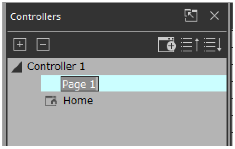
Select [Rename].
Now you can rename the page.
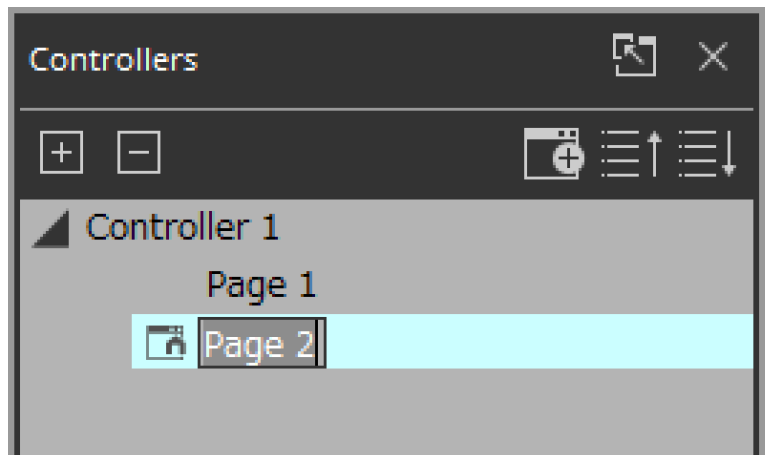
-
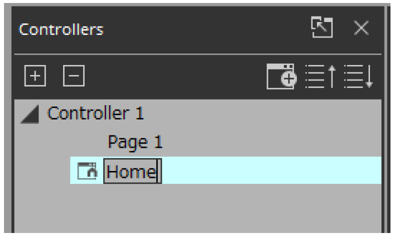
Enter a name for the page.
Since this is the home page for this example, specify “Home.”
-
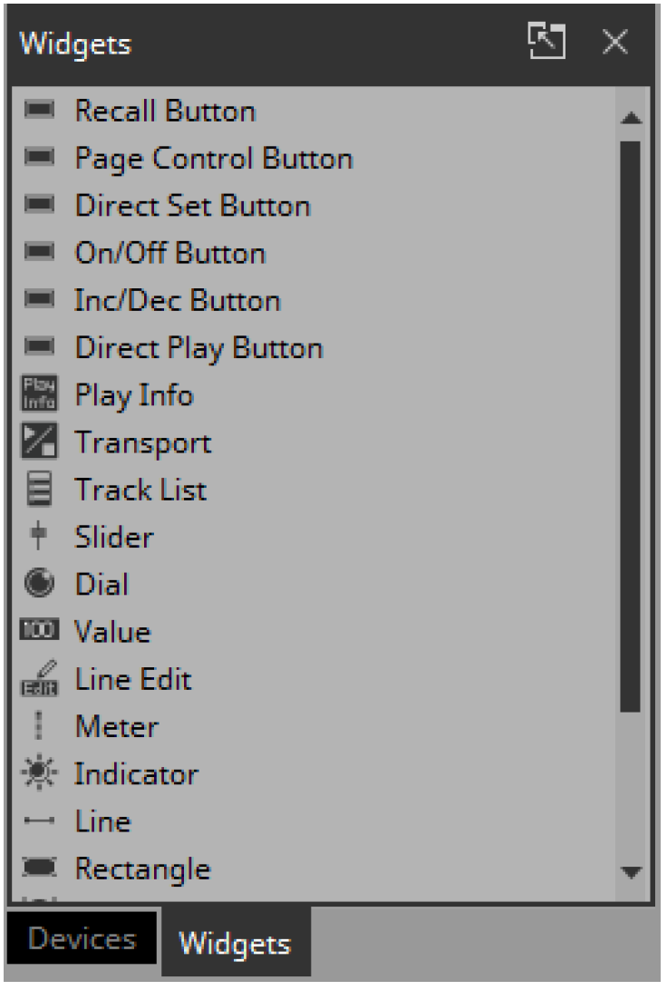
In the “Devices” area, click the [Widgets] tab.
The area switches to the “Widgets” area.
-
Drag and drop [Page Control Button] into the work area.
A button for switching pages is placed in the work area.
-
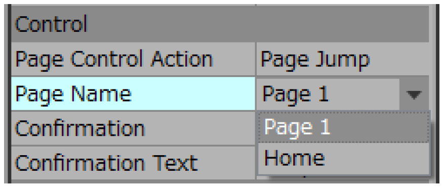
In the “Properties” area’s “Control,” click the column at the right of “Page Name.”
When you click the button, the pages that can be switched are shown as a list.
-
Select [Page 1].
When in control mode, clicking the button will now switch to “Page 1.”
-
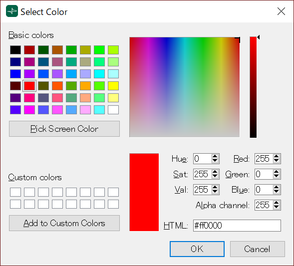
In the “Position/Appearance” area, click the column at the right of “Color.”
The “Select Color” dialog box opens.
-
Select the color for when the button is clicked.
For this example, select red.
-
Click the [OK] button.
The dialog box closes, and the button turns red.
-
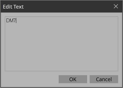
In the “Label” area, click the column at the right of “Text.”
The “Edit Text” dialog box opens.
-
Enter a name for the button.
For this example, specify “DM7.”
-
Click the [OK] button.
“DM7” is shown below the button.
-
In the “Controllers” area, right-click [Page 1].
The Page 1 work area appears, and the context menu appears.
-
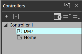
Select [Rename].
Now you can enter a name for “Page 1” from the keyboard.
-
Enter a name for the page.
In this example, this page is specifically for the DM7, so specify “DM7.”
-
From the “Widgets” area, drag and drop [Page Control Button] into the work area.
A button for switching pages is placed in the work area.
-
In the “Properties” area’s “Control,” click the column at the right of “Page Name.”
When you click the button, the pages that can be switched are shown as a list.
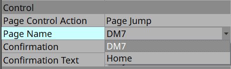
-
Select [Home].
When in control mode, clicking the button will now switch to “Home.”
-
In the “Position/Appearance” area, click the at the right of “Image.”
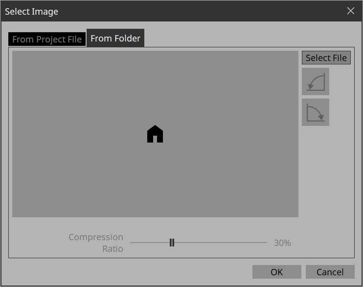
The “Select Image” dialog box opens.

-
*Go to the Form Folder tab, click the [Select File] button, and select any image file on your computer. *
In this example, we use an icon of a house.SVG images are installed in the ImageFile folder. Feel free to use them.
SVG images cannot be displayed as thumbnails in File Explorer of Windows. Click on the image to view it in the preview window of File Explorer.
-
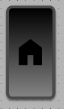
Click the [OK] button.
The dialog box closes, and the image is applied to the button that moves to the “Home” page.
4.5. Specifying a background for the page
If you want to specify a background, you’ll save time by specifying the background before you adjust the placement of the widgets.
-
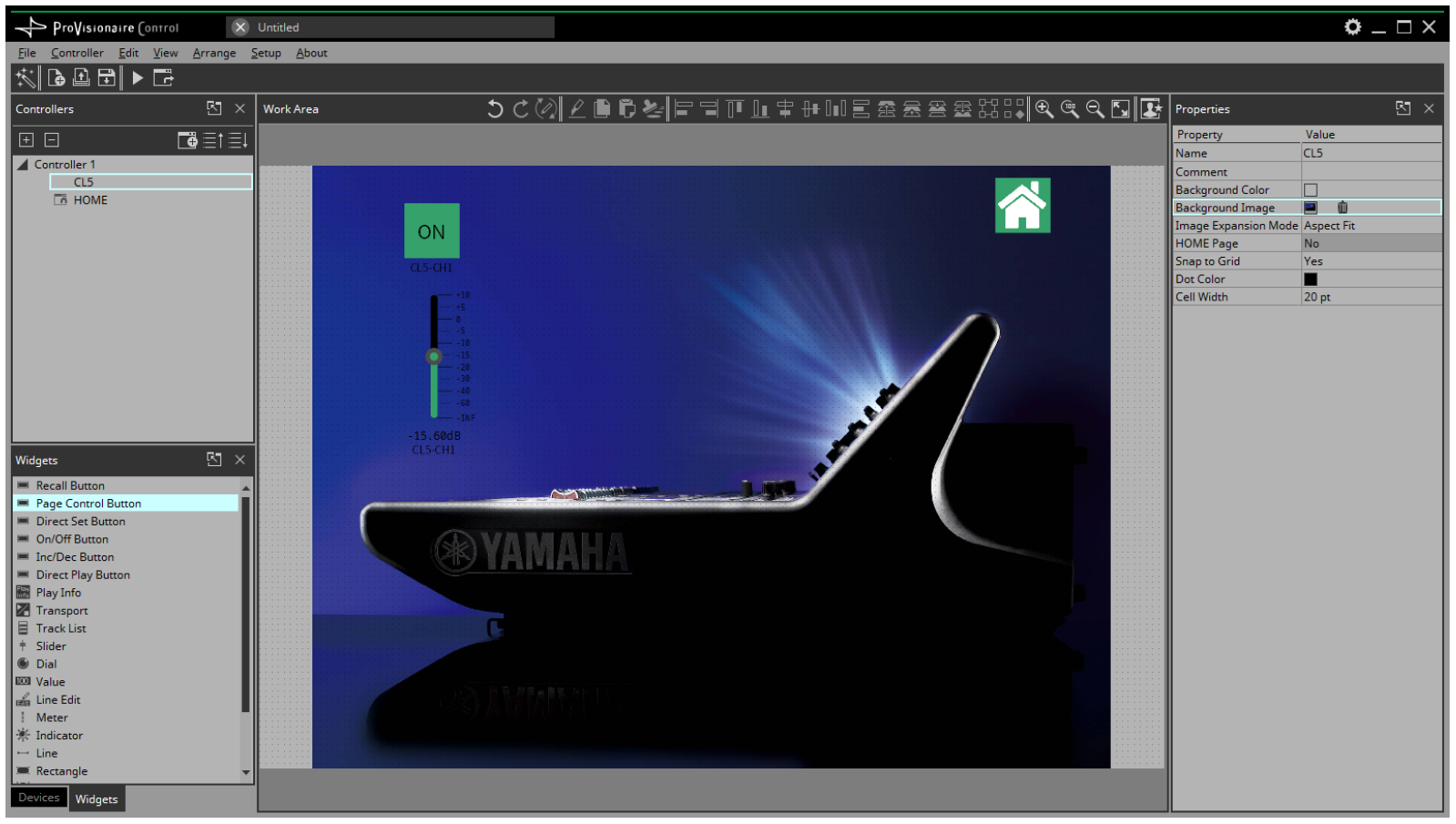
Click somewhere in the work area where there is no widget.
“Properties” shows the settings of the page.
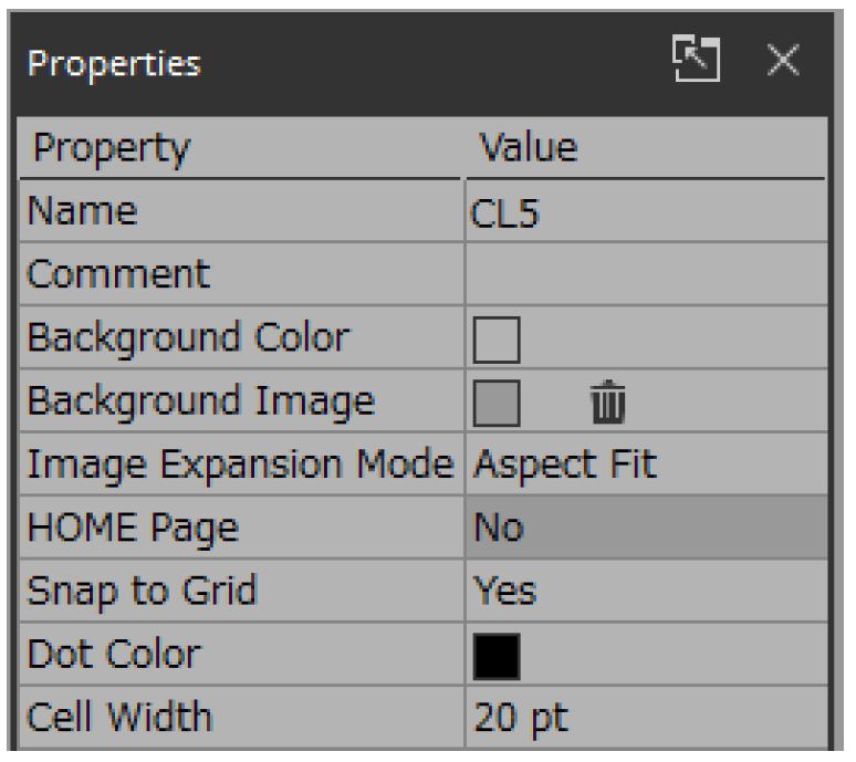
-
Click the □ at the right of “Background Image.”
The “Select Image” dialog box opens.
-
Click the [From Folder] tab.
-
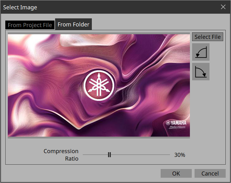
Click the [Select File] button, and select an image.
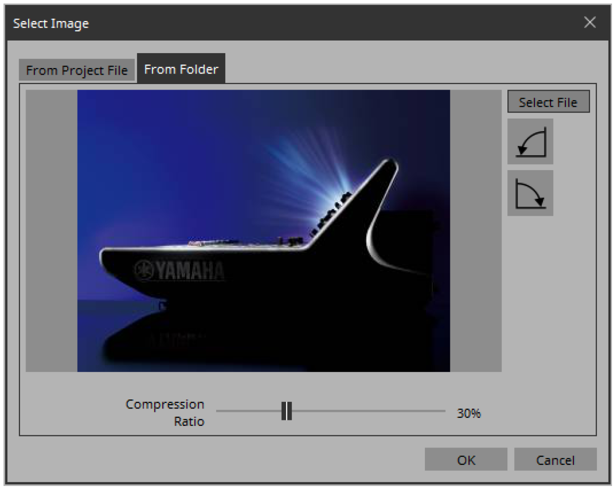
-
In the “Select Image” dialog box, use the [Compression Ratio] slider to change the compression ratio.
Since this image data is embedded in the project file or controller file, a lower compression ratio will increase the size of the file.
A large file size will affect the operation of the overall application, so we recommend that you compress the image a certain amount to decrease the file size. -
Click the [OK] button.
4.6. Adjusting the placement of the widgets
Now we’ll make adjustments while watching the widgets that we placed.
-
On the menu bar, click the [Fit to Screen] button
 so that the entire page is visible.
-
To change the size of the widget, and then adjust its size by clicking and dragging the white squares □ that are shown around its edges.
-
Drag and drop the widget to adjust its position.
-
As necessary, use the “Properties” area to adjust the text size etc. of the label.
Perform these steps for each page.
4.7. Saving the project file
Let’s save the project that we created so far.
-
On the menu bar, click the [Save] button
 .
.
The “Save File” dialog box appears.
If file was saved, it is overwritten by the saved data. -
If the “Save File” dialog box appears, specify a save location for the file, assign a file name, and save it.
4.8. Testing operation
Let’s operate the widgets on each page to verify that they work. We assume that there is a device that is being controlled.
-
Power-on the device.
-
Connect the computer to the network that is connected to the device’s NETWORK port.
-
On the title bar, click the [Setup] button
 .
.
The “Setup” dialog box opens.
-
Select the network interface card that is connected to the network that is connected to the device’s NETWORK port.
Up to eight network adapters can be selected at the same time. -
Click the [OK] button.
The dialog box closes. -
In the “Controllers” area, select the controller that you want to operate.
-
On the tool bar, click the [Run] button
 .
.
Kiosk starts.
The operation when a controller file is loaded in Kiosk can be checked. -
Note that the indication “All Devices are ONLINE” is shown in the upper right.
If this indicates “All Devices are OFFLINE,” then Kiosk has not detected the devices. Make sure that the network settings of the devices and the computer are correct. -
Click the button labeled “DM7.”
The page changes.
-
Operate the fader and button, and verify that they are linked with the device.
If you want to edit the placement etc., exit Kiosk and proceed as described in “Adjusting the placement of the widgets.” The changes are not applied if Kiosk is left running. -
Exit Kiosk.
4.9. Making security settings
You can set a screen lock to prevent unauthorized persons from making inadvertent changes to a system in operation.
Now we’ll specify the screen lock settings and the various pass codes used to unlock restricted functions.
-
On the title bar, click the [Setup] button
.
The “Setup” dialog box opens.
-
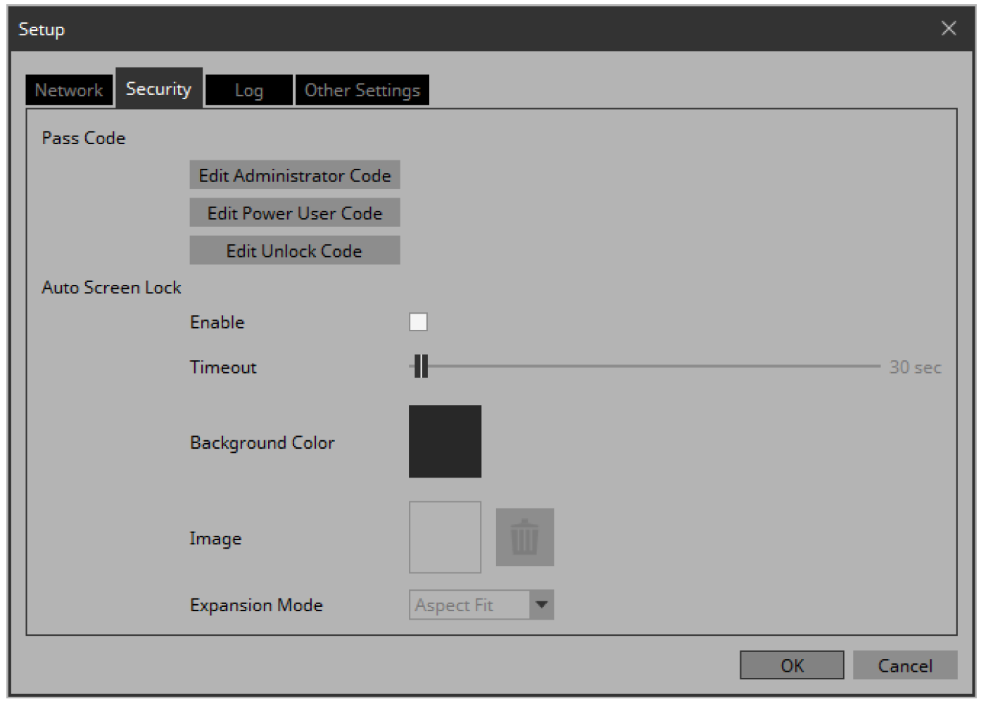
Click the [Security] tab.
The security settings screen appears.
-
Click the [Edit Administrator Code] button.
The “Edit Pass Code” dialog box appears, with “Administrator” shown in the upper left.
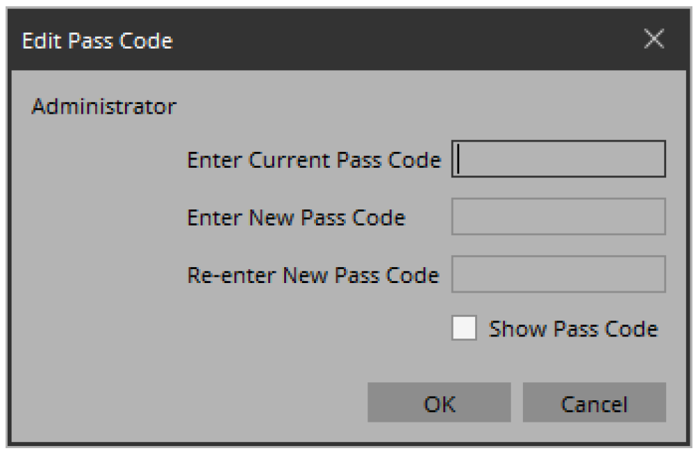
-
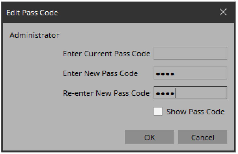
Enter the same four-digit number into the [Enter New Pass Code] text box and the [Re-enter New Pass Code] text box.
The number that you entered will be the administrator pass code.
Since a pass code is not specified by default, leave the [Enter Current Pass Code] text box blank.
-
Click the [OK] button.
The administrator pass code is confirmed. -
In the same way, click the [Edit Power User Code] button or the [Edit Unlock Code] button to specify pass codes for power users or for staff.
Since the staff pass code can be changed by the power user, you don’t need to specify the staff pass code if the power user will specify it. -
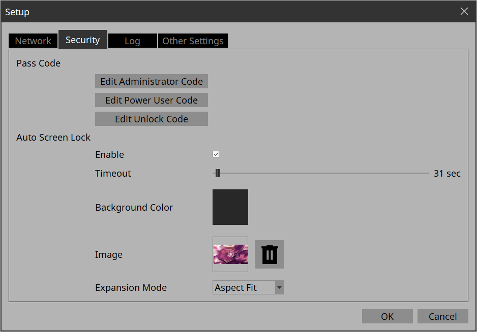
In the Screen Lock area, select the [Enable] check box.
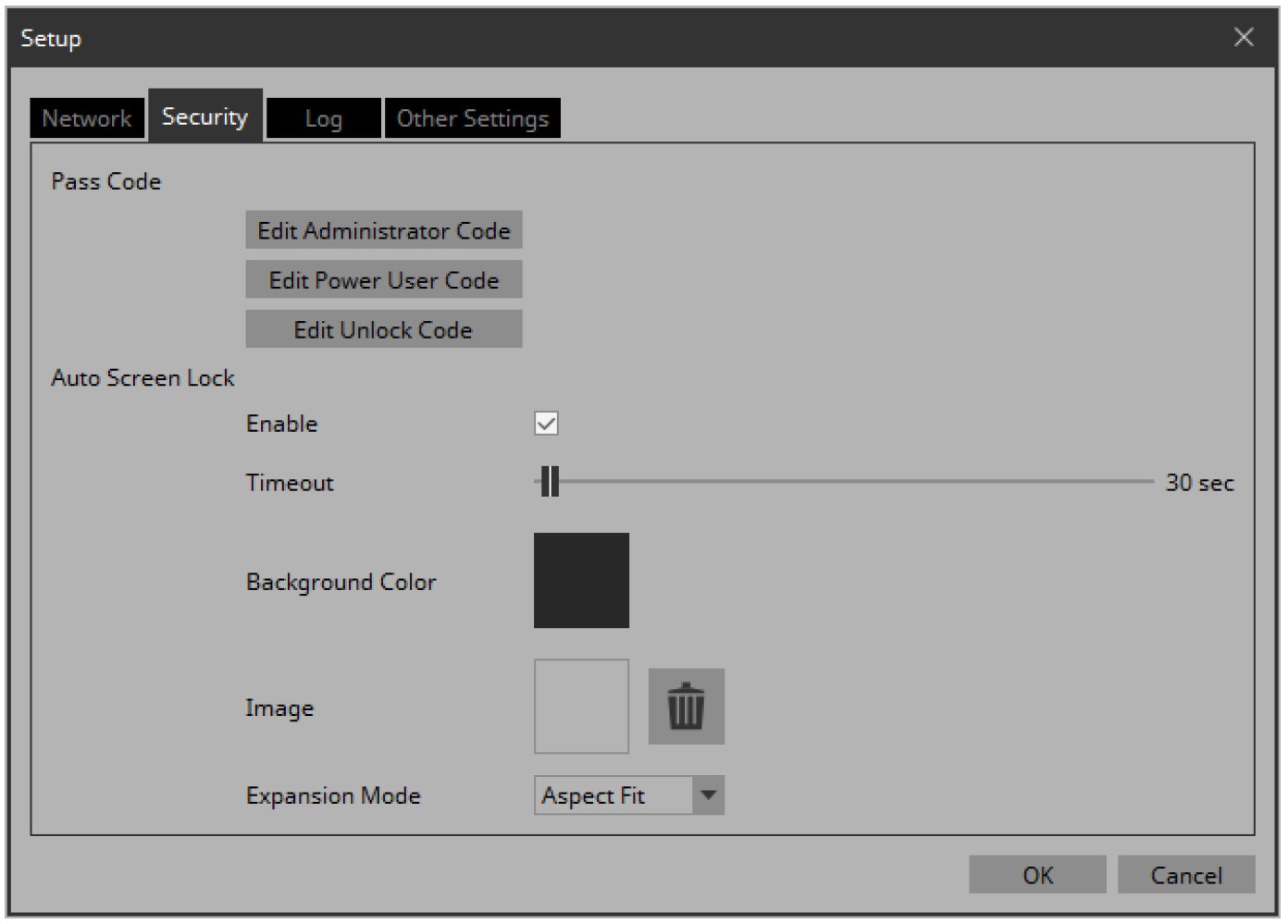
-
Use the [Timeout] slider to specify the number of seconds since the last operation until the screen is locked.
-
Specify the display when the screen is locked.
If you want to specify a solid color, click the [Background Color] field. The color selection screen appears.
If you want to specify an image, click the □ at the right of [Image]. In this example we will specify an image, so click the □. -
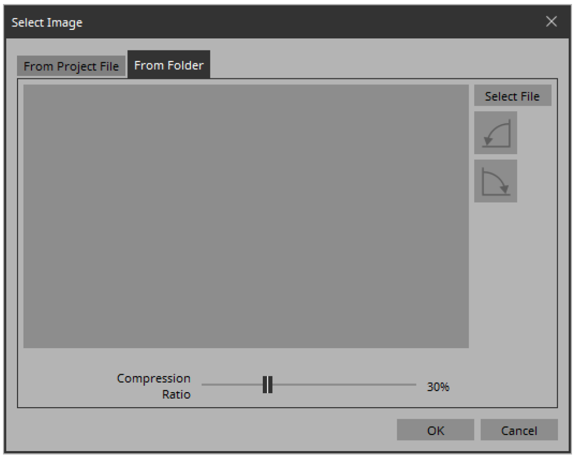
Click the [From Folder] tab.
A screen appears, allowing you to apply an image file from the computer.
-
Press the [Select File] button, and select the image file that is shown when the screen is locked.
-
In the “Select Image” dialog box, use the [Compression Ratio] slider to change the compression ratio.
Since this image data is embedded in the project file or controller file, a lower compression ratio will increase the size of the file.
| For SVG files, Compression Ratio is disabled. |
-
Click the [OK] button.
Close the dialog box to return to the “Setup” dialog box.
-
Click the [OK] button.
The dialog box closes. -
On the tool bar, click the [Run] button
.
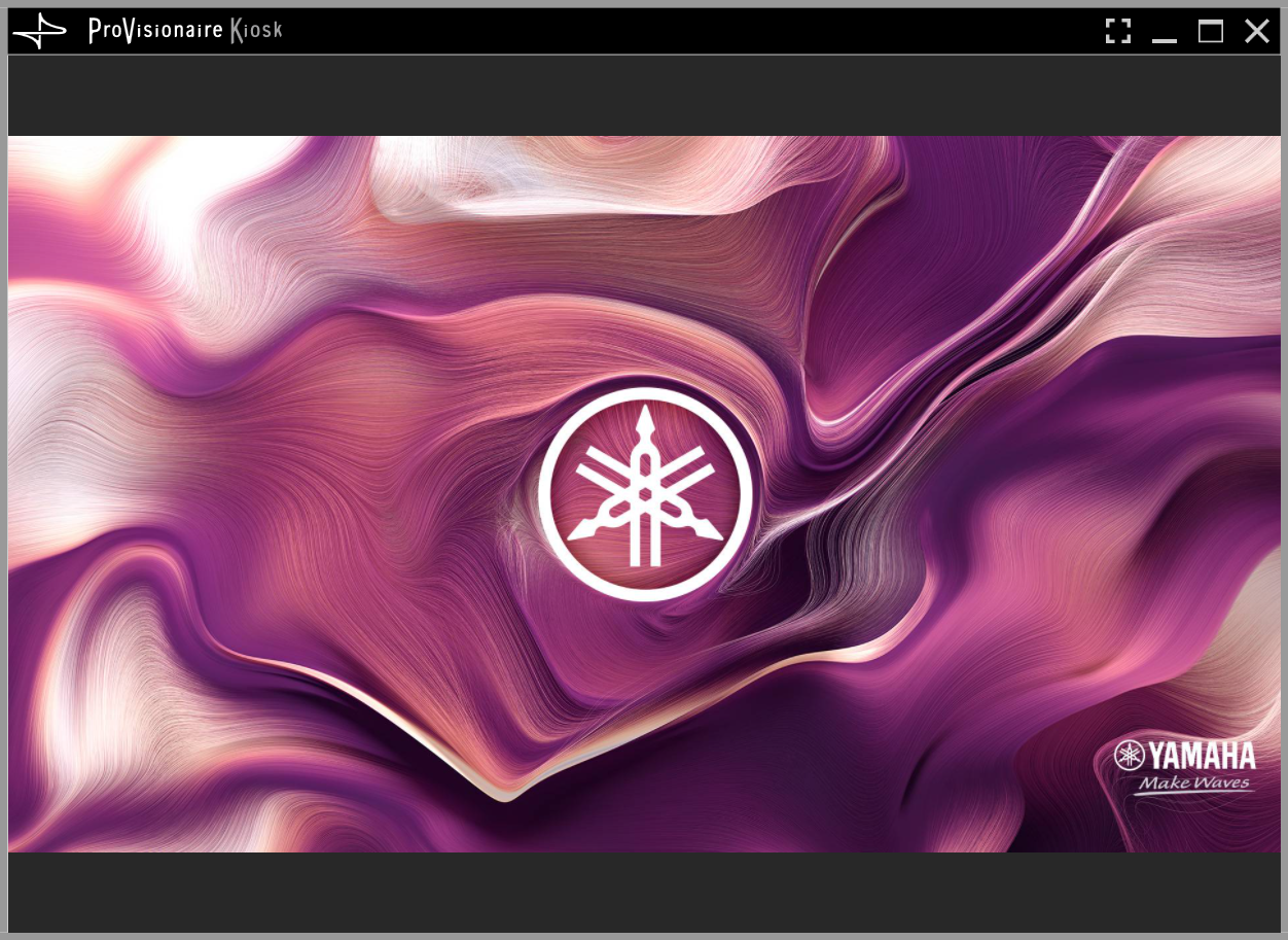
Kiosk starts.
-
Refrain from performing any operation for the length of time specified by the [Timeout] slider.
The lock screen appears.
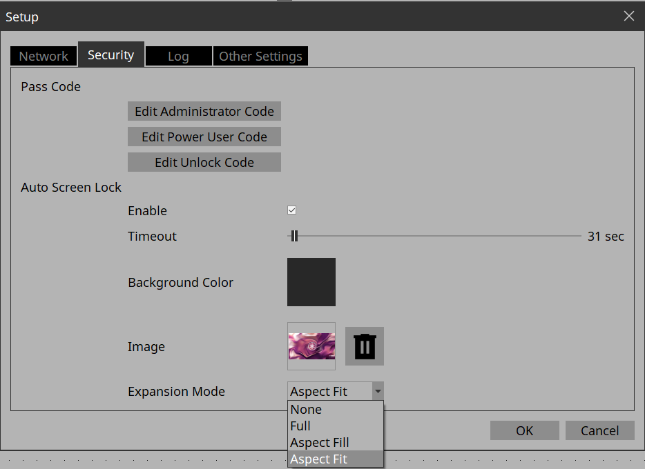
If you want to change the appearance of the image, exit Kiosk, and in the “Setup” dialog box’s [Security] tab, use [Expansion Mode] to change the appearance.
-
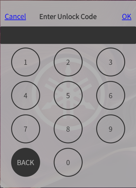
Click the lock screen.
The screen indicates “Enter Unlock Code,” allowing you to unlock the screen.
If you did not specify an “Edit Unlock Code” in step 6, you return to the screen without any “Enter Unlock Code” indication. -
Click to enter the Unlock Code that you specified in step 6.
4.10. Creating a controller file
Here’s how to create a controller file for Kiosk installed on the actual operating terminal.
-
In the “Controllers” area, select the controller for which you want to create a controller file.
-
On the tool bar, click the [Export] button
 .
.
The “Export Controller File” dialog box opens. -
Assign a file name, and click [Save].
Select the [To Your Computer] tab and click [Select Destination Folder]. A file save dialog box opens.
Select a save location and click [Save] to save the controller file.
| To send controller files to your iPad/iPhone, refer to “Export Controller File” dialog box . |