Dialog boxes and windows
17. Dialog boxes and windows
Here we explain the dialog boxes and windows.
17.1. “Setup” dialog box
In this dialog box you make settings for the entire project or controller.
You can open this dialog box from the [Setup] menu or [Setup]
![]() on the title bar.
on the title bar.
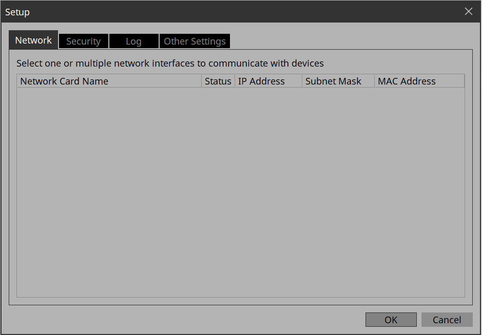
[Network] tab
Here you can select the computer’s network interface card (subsequently called the “network card”) used for communicating with devices.
|
You can select up to eight network cards.
When using more than one network card, each card must have a unique network address. |
If the computer is not connected to the network, click the [Cancel] button to close the dialog box.
-
[Network Card Name]
Indicates the name of the network card. -
[Status]
Indicates the status of the network card (Up or Down). -
[IP Address]/[Subnet Mask]
Indicates the IP address and subnet mask that are assigned to the network card.
You cannot use network cards for which "0.0.0.0" is displayed for reasons such as not being physically connected. -
[MAC Address]
Indicates the MAC address of the network card. -
[OK] button
Updates the settings and closes the dialog box. -
[Cancel] button
Closes the dialog box without updating the settings.
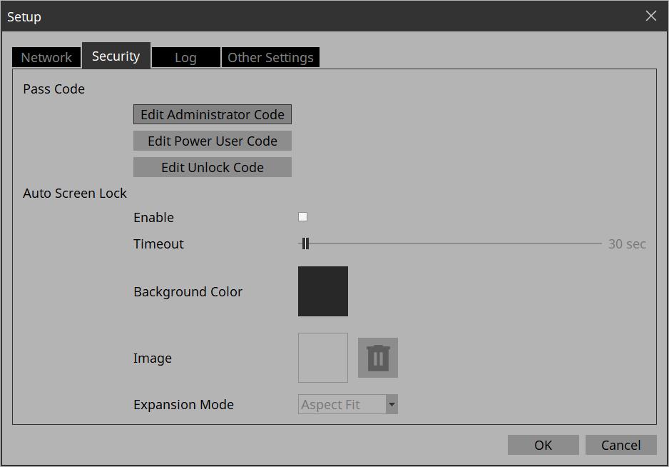
[Security] tab
Here you can make security settings.
-
Pass Code [Edit Administrator Code]/[Edit Power User Code]/[Edit Unlock Code] buttons
Click a button to open the “Edit Pass Code” dialog box.
When entering a pass code for the first time, leave the [Enter Current Pass Code] field empty when you specify the pass code. -
Auto Screen Lock [Enable] check box
If this is selected, you can make screen lock settings. -
Auto Screen Lock [Timeout] slider
Specifies the time until screen lock occurs. -
Auto Screen Lock [Background Color] button
Click this to open the “Select Color” dialog box. Specify a background color that is used when the image is not shown in the full screen. -
Auto Screen Lock [Image] button
Click this to open the “Select Image” dialog box. Select an image file that is shown when the screen is locked. -
Auto Screen Lock Image trash can button
Cancels the selection of the image specified by the Screen Lock [Image] button. Even if this selection is canceled, the image remains embedded into the project file. -
Auto Screen Lock [Expansion Mode] list box
From the list, select how the image will be shown in the display area. For details on these choices, refer to About the Expansion Mode -
[OK] button
Updates the settings and closes the dialog box. -
[Cancel] button
Closes the dialog box without updating the settings.
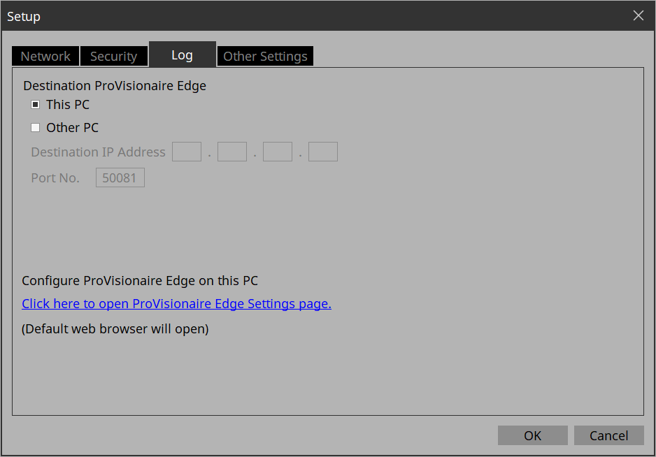
[Log] tab
Specify the ProVisioniare Edge to be connected.
-
[This PC] radio button
Displays device operation information collected by the ProVisionaire Edge installed on the computer you are currently operating in the “System Monitor” window. -
[Other PC] radio button
Displays device operation information collected by the ProVisionaire Edge installed on another computer in the “System Monitor” window. -
[Destination IP Address] text box
If the [Other PC] radio button is enabled, enter the IP address of the computer. -
[Port No.] text box
Enter the port number used by “ProVisionaire Edge” on the other computer. The default value at installation is 50081.
If you manually change the port number that is used by “ProVisionaire Edge” on the other computer, you must also change the firewall settings of the other computer. -
[Click here to Open PV Monitoring Service Configuration page] link
Click here to display the “ProVisionaire Edge Settings” screen of the “ProVisionaire Edge” installed on the computer you are currently using in your default web browser.
This cannot be displayed if Internet Explorer is specified as the default web browser, so you must specify a different web browser as the default web browser. -
[OK] button
Updates the settings and closes the dialog box. -
[Cancel] button
Closes the dialog box without updating the settings.
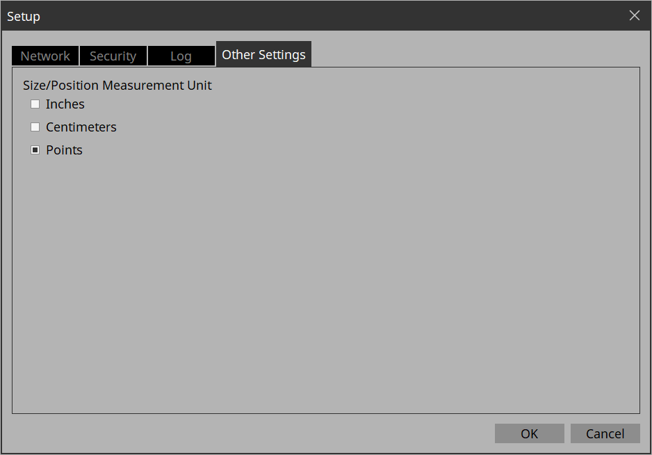
[Other Settings] tab
Here you can specify the units for the size and position information of the widgets.
This setting is saved in the computer, not in the project file.
-
「Size/Position Measurement Unit」radio buttons
Here you can select the units for the size and position information of the widgets. -
[OK] button
Updates the settings and closes the dialog box. -
[Cancel] button
Closes the dialog box without updating the settings.
17.2. “New Project Wizard” dialog box
Use this dialog box to create a new project.
Open it from [New Project] under the [File] menu.
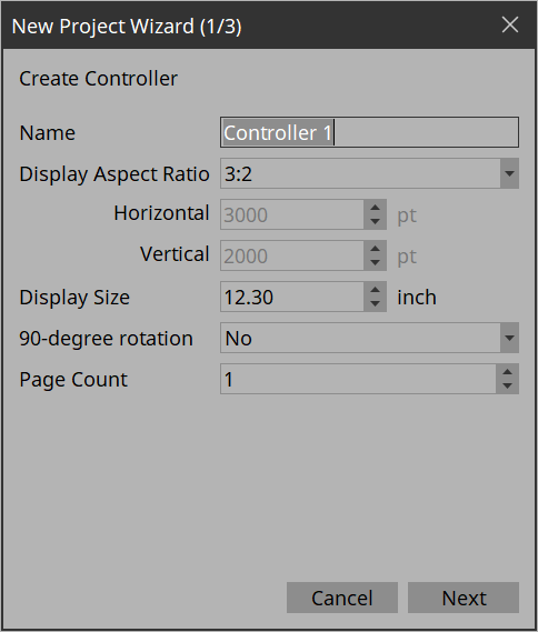
1/3: Create Controller
Here you can make settings for a new controller.
-
[Name] text box
Specifies the name of the controller. -
[Display Aspect Ratio] spin box
The screen ratio (horizontal:vertical).
Adjust the screen ratio to match that of the device where Kiosk will be installed.
When you select Custom, directly enter the Horizontal and Vertical values.
You can change the screen ratio later in “Properties” of the controller.-
[Horizontal] spin box
Specifies the horizontal size of the controller when Display Aspect Ratio is set to Custom. -
[Vertical] spin box
Specifies the vertical size of the controller when Display Aspect Ratio is set to Custom.
-
-
[Display Size] list box
The diagonal length of the controller.
Adjust the display size to match that of the device on which Kiosk will be run.
This is the basis for displaying the widget size and position in centimeters or inches. -
[90-degree rotation] list box
Select (Yes) to swap the vertical and horizontal dimensions of the controller. -
[Page count] list box
Specifies the number of pages for the controller. -
[Cancel] button
Discards the settings and closes the dialog box. -
[Next] button
Moves to the next settings page.
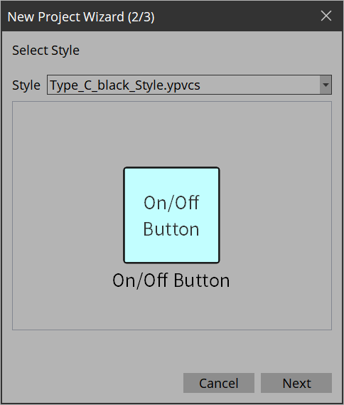
2/3: Select Style
Selects which style file to use when creating a controller.
-
[Style]
Select a style.
The style can also be changed later in [Style] under the [Setup] menu.
Select “User” to open the file selection dialog box. You can select an individually-created style file. -
[Preview]
Displays a sample of the widget. -
[Next] button
Moves to the next settings page.
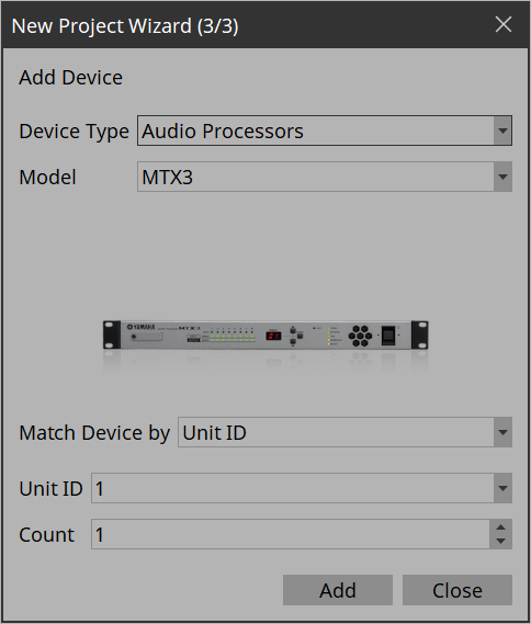
3/3: Add Device
Select the device you want to register to the project.
-
[Device Type] list box
Selects the type of device. -
[Model] list box
Selects the device. -
[Match Device by] list box
Selects the search method for devices on the network.
If you select [Unit ID], the [Unit ID] list box and [Count] spin box are shown below.
If you select [IP Address], the [IP Address] text box is shown below.
If you want to control a device that is on a different subnet than Kiosk, select [IP Address]. -
[Unit ID] list box
Selects the starting unit ID of the devices that you want to register. -
[Count] spin box
Specifies the number of units of the devices that you want to register. -
[IP Address] text box
Specifies the IP address of the device that you want to register. -
[Add] button
Registers the device(s). -
[Add & Close] button
Registers the device(s) and closes the dialog box. -
[Close] button
Closes the dialog box without registering a device.
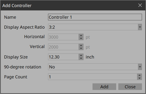
17.3. “Add Controller” dialog box
Here you can add a controller to the project.
Open this dialog box from “Add”
![]() in the “Controllers” area.
in the “Controllers” area.
For details on the settings, refer to “New Project Wizard” dialog box .
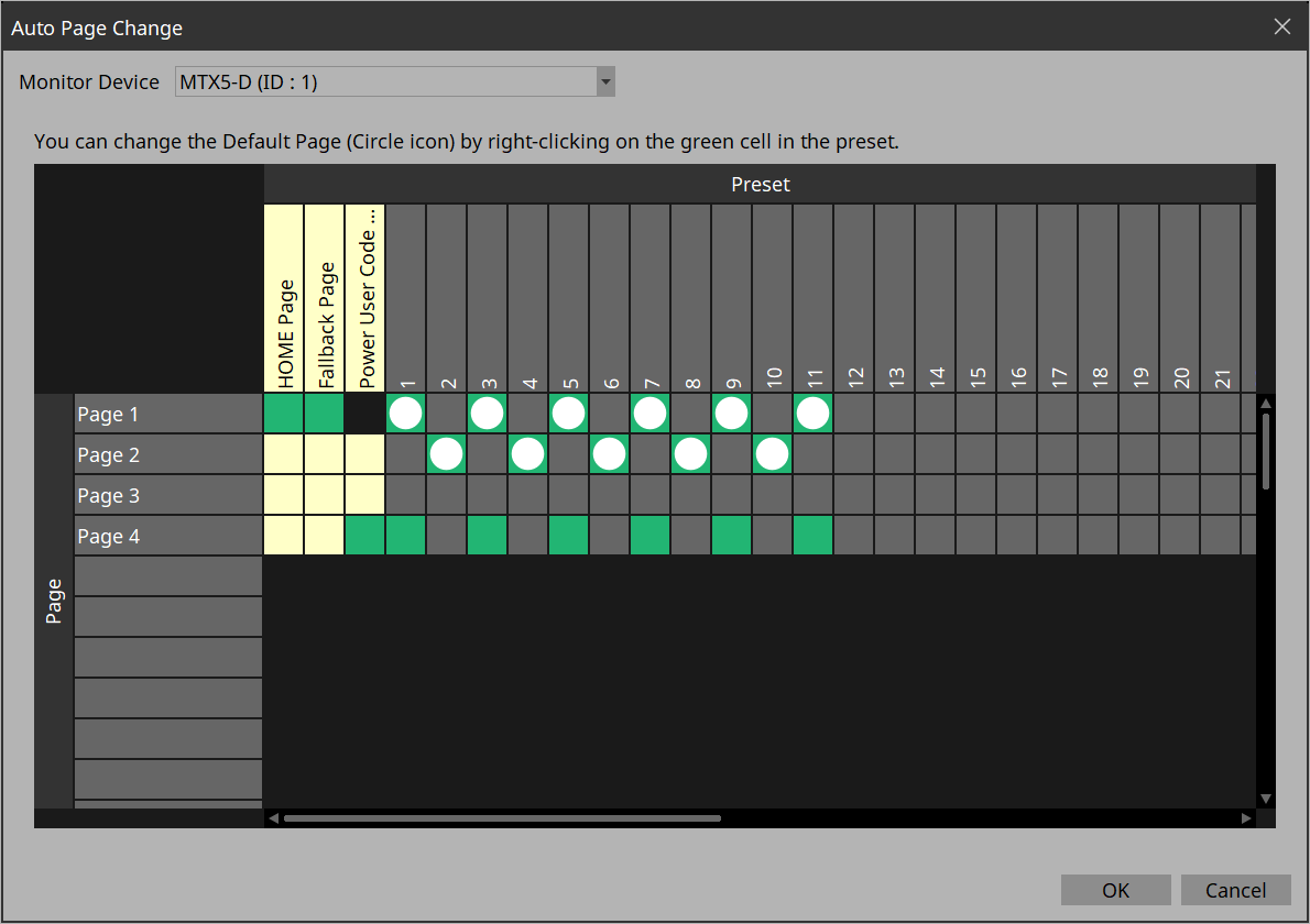
17.4. “Auto Page Change” dialog box
You can switch the page set to be displayed on Kiosk according to the preset numbers recalled on any device.
Open this dialog box from [Auto Page Change] under the [Controller] menu or from Properties > Auto Page Change under Controller.
-
Monitor Device
Selects which device will be the target of page changes when presets are recalled.
Select from the devices registered in Devices. Target devices are MTX3/MTX5-D/MRX7-D/DME Series/RM-CR.
Once the device is set, when you recall a preset on a device, you will be able to select only the specific pages in the Kiosk title bar > Page List.
For DME Series, snapshots must be registered in advance.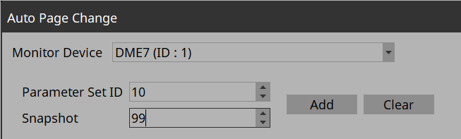
Click the [Clear] button to delete the snapshot selected in the Preset field.
-
Page lines
Displays the pages added to Controller. -
Home Page column
Click a cell to select a page to be specified as Home. -
Fallback Page column
Click a cell to select a page to be specified as Fallback. -
Power User Code Required column
Before moving to a page where this cell is turned on, authentication with a Power User code is required.
You cannot select pages for which Home Page or Fallback Page is turned on.
-
Preset columns
Displays the Monitor Device presets.
You can select multiple pages for one preset.
The selected pages will be displayed on the Page List button on the title bar when the preset is recalled.
Right-click on the selected page to set it as the Default Page.
The Default Page is the page that is first displayed when a preset is recalled.
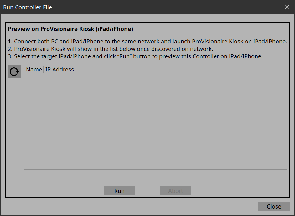
17.5. “Run Controller File” dialog box
Preview the controller you are creating on Kiosk (iPad/iPhone) on the same network.
Open the dialog box from [Run Controller File] under the [Controller] menu.
-
 (Refresh) button
Re-searches for Kiosks on the network and updates the list. -
[Name]/[IP Address]
Displays information about iPads/iPhones that are connected to the same network as the network card selected in the Network tab of the “Setup” dialog box.
Select the transfer destination for the controller file. -
[Run] button
Transfers the controller file to the iPad that is selected. The receiving ProVisionaire Kiosk shows a confirmation screen. -
[Abort] button
Cancels controller file transfer. -
[Close] button
Closes the dialog box.
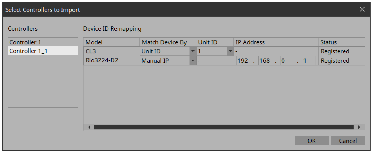
17.6. “Select Controllers to Import” dialog box
This dialog box imports controller files from other projects.
Open it from [Import] under the [Controller] menu.
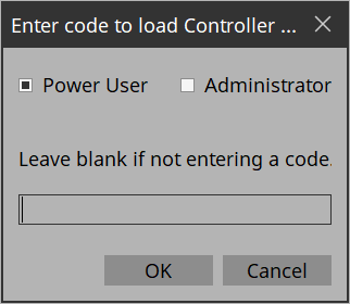
When a file is selected, a dialog box opens to allow you to select a passcode.
-
Leave blank if not entering a code.
If a passcode is set to the file to be imported, enter the passcode.
If a passcode is not set, simply click OK.
Click the [OK] button to open the “Import Controller File” dialog box.
-
Controllers
Displays a list of the controllers contained in the project file. Select a controller to be imported. When a controller is selected, Device ID Remapping on the right side lists the devices used in the controller. -
Device ID Remapping
When importing controllers, you can collectively convert the identification information of the devices in use.
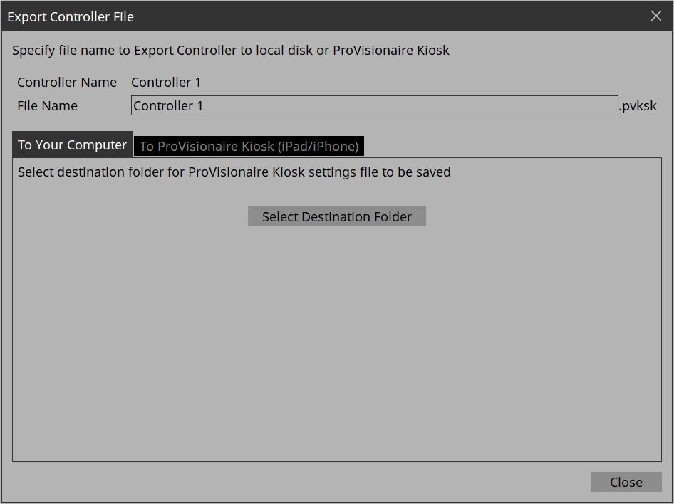
17.7. “Export Controller File” dialog box
Save controller files to a computer or send them to your iPad/iPhone or DME.
Open this dialog box from [Export] under the [Controller] menu or from Export
![]() on the toolbar.
on the toolbar.
| As of ProVisionaire Control PLUS V3.1, files can be sent only to DME5/3. |
-
[Controller Name]
Displays the name of the controller currently selected in the Controllers area. -
[File Name] text box
Enters the name of the controller file. -
[Close] button
Closes the dialog box.
17.7.1. [To Your Computer] tab
Select this when you want to save the control file to the computer.
-
[Select Destination Folder] button
Selects the save-destination for the controller file and save the controller file.
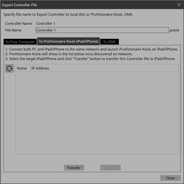
17.7.2. [To ProVisionaire Kiosk] tab
Sends a controller file directly to an iPad/iPhone where Kiosk is running.
-
(Refresh) button
Updates the iPad list. -
[Name]/[IP Address]
Displays information about iPads/iPhones that are connected to the same network as the network card selected in the Network tab of the “Setup” dialog box.
Select the transfer destination for the controller file. -
[Transfer] button
Sends a controller file to the selected iPad/iPhone. -
[Abort] button
Cancels controller file transfer.
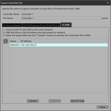
17.7.3. [to DME] tab
Send controller files to a DME on the same network.
| As of ProVisionaire Control PLUS V3.1, files can be sent only to DME5/3. |
-
(Refresh) button
Updates the list of DMEs that exist on the network. -
[Name]/[IP Address]
Displays information about DMEs that are connected to the same network as the network card selected in the Network tab of the “Setup” dialog box. Select the transfer destination for the controller file. -
[Transfer]button
Sends a controller file to the selected DME. -
[Abort]button
Cancels the controller file transfer. -
[Edit CCP Code]button
Changes the Custom Control Panel Code (CCP Code) of the selected DME.
If you set a CCP Code, you must enter the CCP Code when transferring a controller file to the DME.
| One DME can hold only one controller file. If the DME is already holding a file, sending another file will overwrite it. |
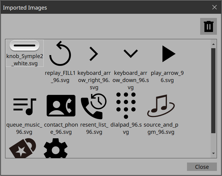
17.8. “Imported Images” dialog box
Here you can view or delete image data embedded in the project file.
Open the dialog box from [Imported Images] under the [Edit] menu.
-
Image tile
Shows the image data embedded in the project file.
To delete data, select the tile of the file that you want to delete. -
Trash con button
Deletes the data whose image tile is selected from the project file. -
[Close] button
Closes the dialog box.
| The data includes images used in the style. |
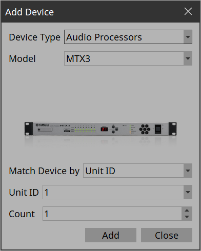
17.9. “Add Device” dialog box
Here you can add a device to the project.
Open this dialog box from [Add Device]
![]() in the “Devices” area.
in the “Devices” area.
-
[Device Type] list box
Selects the type of device. -
[Model] list box
Selects the device. -
[Match Device by] list box
Selects the search method for devices on the network.
If you select [Unit ID], the [Unit ID] list box and [Count] spin box are shown below.
If you select [IP Address], the [IP Address] text box is shown below.
If you want to control a device that is on a different subnet than Kiosk, select [IP Address]. -
[Unit ID] list box
Selects the starting unit ID of the devices that you want to register. -
[Count] spin box
Specifies the number of units of the devices that you want to register. -
[IP Address] text box
Specifies the IP address of the device that you want to register. -
[Add] button
Registers the device(s). -
[Add & Close] button
Registers the device(s) and closes the dialog box. -
[Close] button
Closes the dialog box without registering a device.
| The data includes images used in the style. |
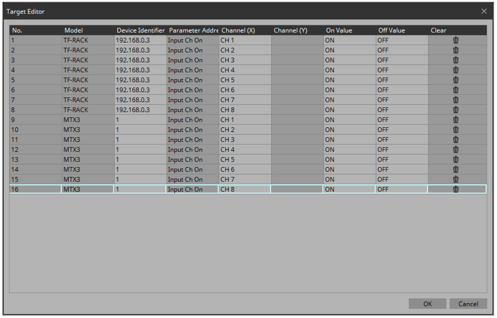
17.10. “Target Editor” dialog box
Here you can show or modify parameter information for buttons (multi buttons) to which are assigned parameters of multiple devices or multiple parameters of a single device.
Open this dialog box from Recall Button, Direct Set Button, or On/Off Button of a widget or from the
![]() button in the “Properties” area > Control of a Slider.
button in the “Properties” area > Control of a Slider.
-
[Model]
Shows the model name of the assigned parameter. -
[Device Identifier]
Shows or changes the UNIT ID or IP address of the assigned parameter. -
[Parameter Address]([On/Off] button、[Direct Set] button、Slider)
Shows the type of the assigned parameter. -
[Channel(X)]/[Channel(Y)]([On/Off] button、[Direct Set] button、Slider)
Shows or changes the channel number of the assigned parameter. -
[On Value]/[Off Value] ([On/Off] button)
Shows or changes whether the assigned parameter is turned on or off when the button is on or off. -
[Preset/Scene/Snapshot]([Recall] button)
Shows the type of the assigned parameter. -
[No.] ([Recall] button)
Displays/changes the preset, scene, and snapshot numbers. -
[Press Value]([Direct Set] button、Slider)
Shows or changes the value that is specified when the button is pressed. -
[Clear]
Clears the assigned parameter. -
[OK] button
Applies the settings and closes the dialog box. -
[Cancel] button
Closes the dialog box without applying the settings.
17.11. “Edit Text” dialog box
Here you can edit the text of a label, etc.
Open this dialog box from the “Properties” area > Text of each widget.
-
Text box
Enter or edit text here. You might or might not be able to enter a line-return, depending on the item. -
[OK] button
Applies the text and closes the dialog box. -
[Cancel] button
Closes the dialog box without applying the entered or edited text.
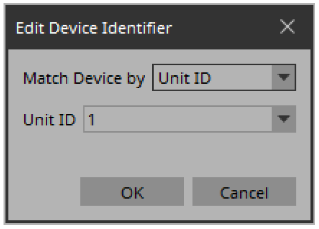
17.12. “Edit Device Identifier” dialog box
Here you can edit the identifying information of a device.
Open this dialog box from the “Properties” area > Identifier of a widget.
-
[Match Device by] list box
Specifies the search method for devices on the network.
If you select [Unit ID], the [Unit ID] list box is shown below.
If you select [IP Address], the [IP Address] text box is shown below.
Devices are searched directly via their IP addresses.If you cannot find the device when you select “Unit ID,” select “IP Address.” -
[Unit ID] list box
Selects the starting unit ID of the devices that you want to register. -
[IP Address] text box
Specifies the IP address of the device that you want to register. -
[OK] button
Applies the settings and closes the dialog box. -
[Cancel] button
Closes the dialog box without applying the settings.
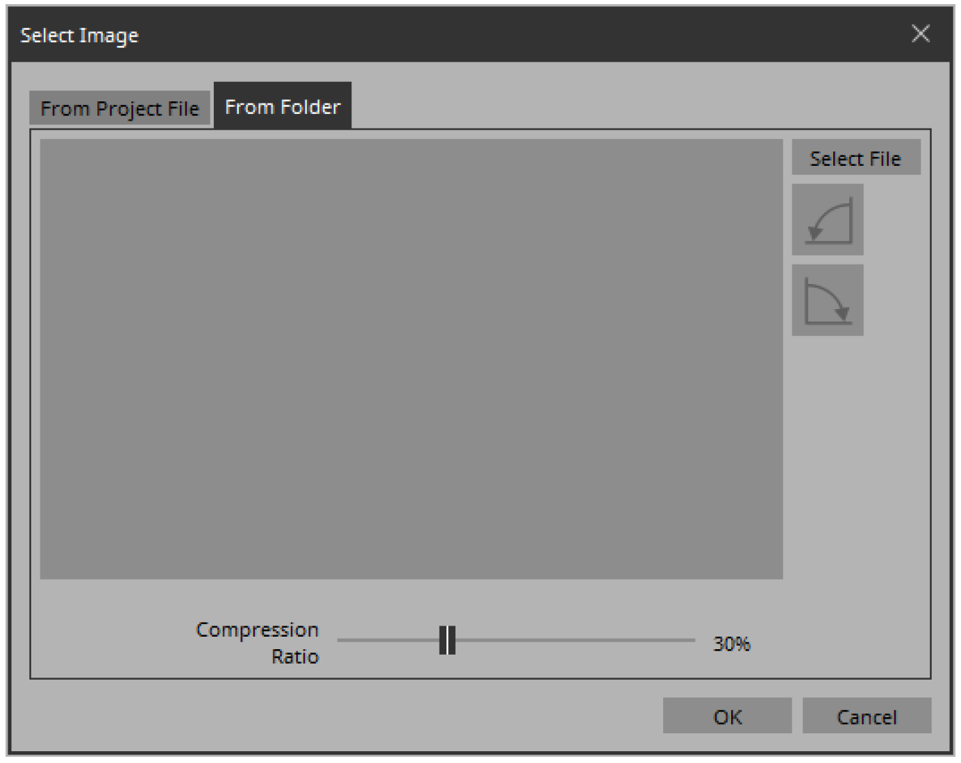
17.13. “Select Image” dialog box
Here you can select image data to use.
Open this dialog box from the “Properties” area > Image, On Image, Off Image, etc., of each widget.
[From Folder] tab
Here you can select an image file from a folder of the computer.
-
[Select File] button
Clicking this button opens a dialog box where you can select an image file.The file selection dialog box cannot display thumbnails of SVG files. Use the preview window of File Explorer. 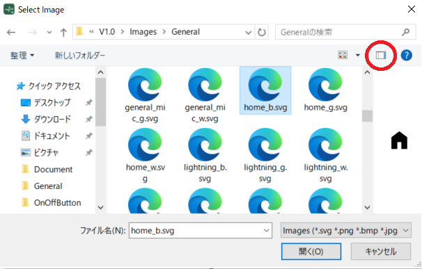
-
Rotate counterclockwise button
Rotates the displayed image 90 degrees counterclockwise. -
Rotate clockwise button
Rotates the displayed image 90 degrees clockwise. -
[Compression Ratio] slider
Specifies the compression ratio when embedding the image in the project file. This slider is disabled when an SVG image is selected. -
[OK] button
Applies the image and closes the dialog box. -
[Cancel] button
Closes the dialog box without applying the image.
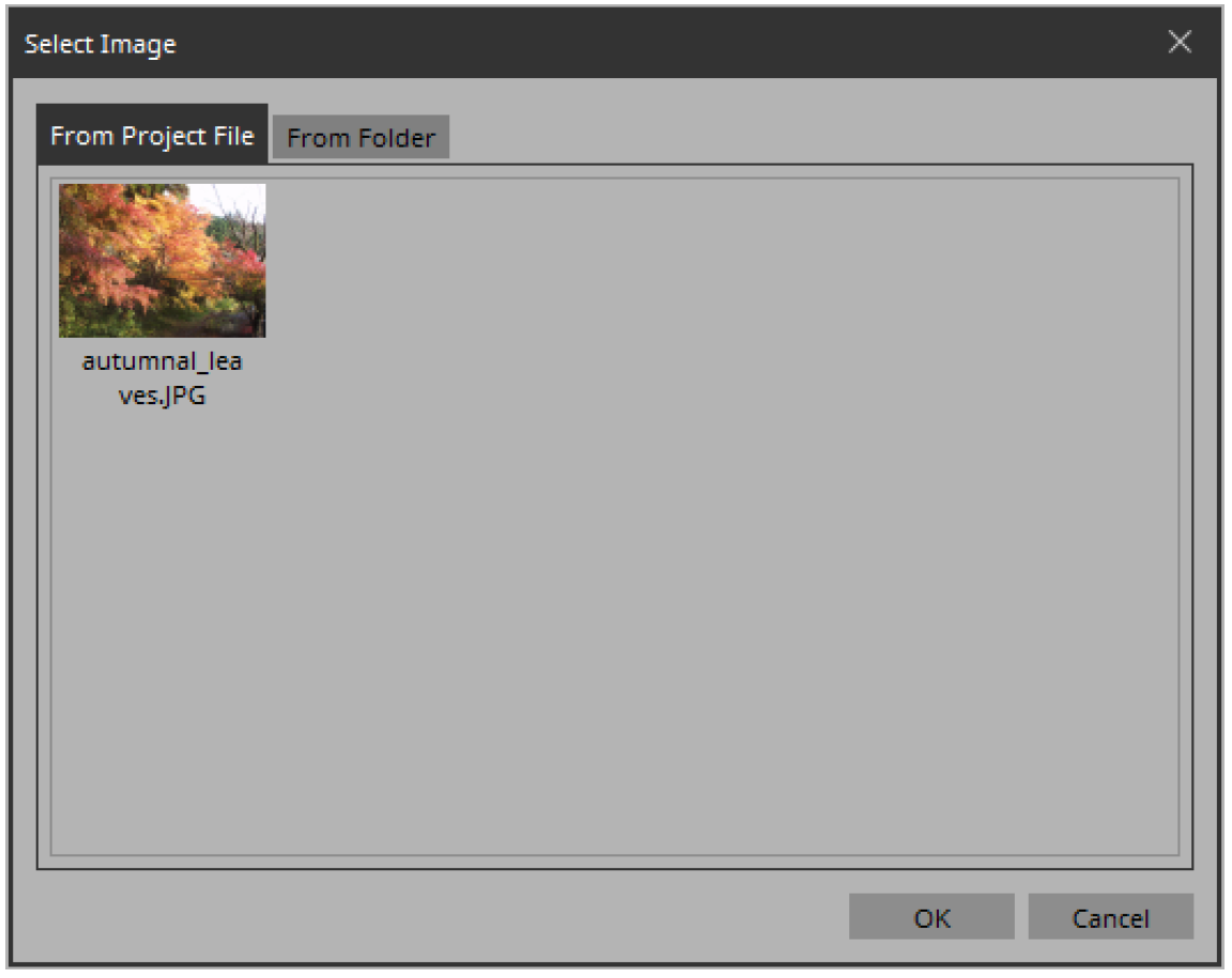
[From Project File] tab
Here you can select image data from the project file.
-
Image tile
Shows the image data embedded in the project file. Select the image that you want to use. -
[OK] button
Applies the selected image and closes the dialog box. -
[Cancel] button
Closes the dialog box without applying the selected image data.
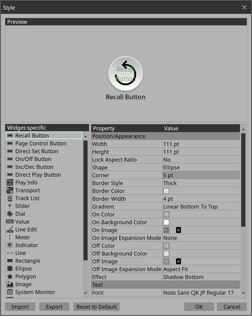
17.14. “Style” dialog box
Check/edit the appearance (style) of the widget when it is placed.
Open this dialog box from [Style] under the [Setup] menu.
-
[Preview]
Displays the style of the widget selected in Widget-specific. -
[Widget-specific]
When you select a widget, the Preview widget is switched, and style information for that widget is shown at the right. -
[Property]/[Value]
Style information of the selected widget. This can also be edited. -
[Import] button
Loads a style file. Changing the style changes how the widget will look when it is placed. -
[Export] button
Saves the current style information as a file. -
[Reset to Default] button
Returns to the style immediately after installation. -
[OK] button
Applies the settings and closes the dialog box. -
[Cancel] button
Closes the dialog box without applying the settings.