The basics of using ProVisionaire Design
3. The basics of using ProVisionaire Design
3.1
Connecting the devices
3.2
Procedure
3.1. Connecting the devices
The connector on the device that will be used to connect to ProVisionaire Design varies depending on the device model. Refer to the connectors listed in the following table.

| Model | Connector |
|---|---|
|
DME series |
Network connector or Dante [PRIMARY] connector |
|
MRX7-D/MTX5-D |
Dante [PRIMARY] connector |
|
MTX3 |
Network connector |
|
EXi8/EXo8 |
Network connector |
|
Rio-D2 series/Tio series/RSio series |
Dante [PRIMARY] connector |
|
Rio-D3 series |
Network connector or Dante [PRIMARY] connector |
|
PC-D/DI series |
Network connector |
|
XMV-D series |
Dante [PRIMARY] connector |
|
XMV series |
Network connector |
|
RM-CG/RM-TT |
Dante/PoE connector |
|
DZR/DXS-XLF series |
Dante connector |
|
VXL1-16P |
Dante/NETWORK connector |
|
VXC2P |
Dante/NETWORK connector |
3.2. Procedure
To use ProVisionaire Design, proceed as described below, depending on whether the power amp is accessible nearby.
If you are constructing a Dante network, also install Dante Controller, and do the patching in Dante Controller.
For more about Dante Controller, refer to the links on the Yamaha Pro Audio website.
https://www.yamahaproaudio.com/
3.2.1. If you can connect the device(s) to the computer
If you are near the power amp(s), you’ll start by setting up the network before you make settings.
The default settings for a PC-series amp are as follows, and assume that you are constructing a redundant network.
| Item | Default value |
|---|---|
|
UNIT ID |
1 |
|
Dante Secondary Port |
Redundant *star connection |
|
IP Setting |
DHCP (if there is no DHCP server, the IP address 169.254.x.x is specified) |
-
Make connections.
Connect the power cords and network cables of the devices.
If you’re using a daisy chain connection, change the "Dante Secondary Port" setting to [Daisy Chain]. -
Turn on the power of all connected devices.
Initialize or update the firmware as needed.
If you want to use ProVisionaire Design to initialize or update the firmware, choose [System] menu → [Device Information], and perform these actions in the "Device Information" dialog box that appears. -
Start ProVisionaire Design.
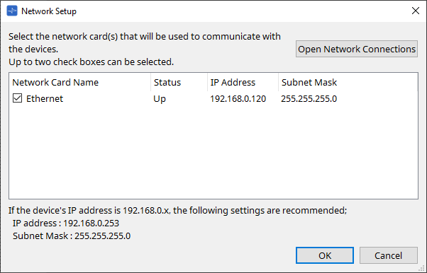
The "Network Setup" dialog box will appear.
Add a check mark to the check box for the network card that will be used to communicate with the devices, and then click the [OK] button.
You can select up to two network cards at a time. In that case, set a different subnet for each network card.
-
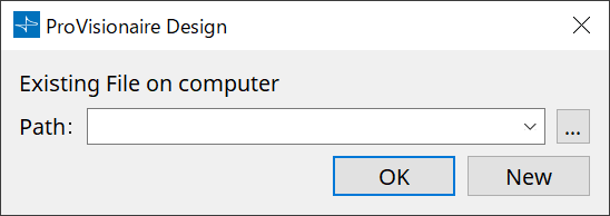
When the startup dialog box appears, click the [New] button.
-
Verify that the devices are shown in the "Network" area.
If they are not shown, check the connections with the devices, and use the "Network Setup" dialog box to verify that the correct network card is connected to the devices. -
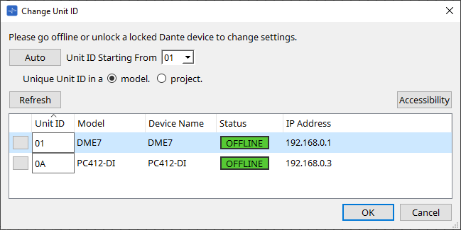
In the "Network" area, click the [Unit ID] button.
The "Change Unit ID" dialog box will appear.
-
Click the [Auto] button.
The UNIT ID of each device is set automatically so that they do not conflict.
| This operation does not apply to the MTX series or XMV series units. Use the dip switches on the rear panel to set the Unit ID. |
-
Click the [OK] button.
The devices will restart, so wait until the devices amps reappear in the "Network" area. -
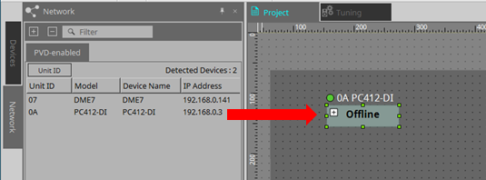
Drag and drop a device from the "Network" area into the "Project" sheet.
The device is registered in the project.
If you hold down < Shift >, click the top device, and then click the bottom device, you can drag and drop all these devices in a single operation.
-
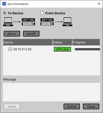
On the tool bar, click the [Online] button.

The "Synchronization" dialog box will appear.
For details on synchronization, refer to
"Online and synchronization"
.
-
Choose [To Device], and then click the [Online] button.
ProVisionaire Design’s settings are sent to each device. -
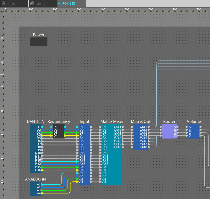
Double-click a device.
The device sheet appears.
-
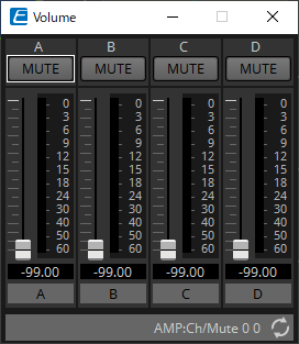
Double-click the component that contains the parameter you want to edit.
The component editor appears.
There are two component editors in each device. One is common and the other is unique to the device. For common component editors, refer to
"ProVisionaire Design Component Guide"
.
For device-specific items, refer to the description of the "Component Editor" for each device.
-
Edit the parameters.
If you want to make the same settings multiple times, right-click and choose [Copy] in the "Project" sheet for the device that you’ve finished editing. On the device to which you want to apply the same settings, choose [Paste Parameters] to apply the copied settings. -
When you are finished editing, save the project file.
You can save by clicking the button.
If you want to protect the file, you can specify a PIN code in the "Protect File" dialog box which you can open from the [File] menu.
|
With the DME, saving the project file while working online will save the file not only on the computer but also on the device.
For more information, refer to the "File Storage" dialog box . |
3.2.2. If you cannot connect the device(s) to the computer
This method lets you virtually place power amps, and then synchronize with the power amps later.
-
Start ProVisionaire Design.
The "Network Setup" dialog box will appear.
Since you will be working offline, click the [Cancel] button in this case.
-
When the startup dialog box appears, click the [New] button to create a new project file.
If you want to edit a project file, click the […] button, select the project file, and click the [OK] button.
-
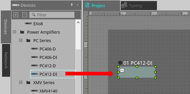
Drag and drop a device from the "Devices" area into the "Project" sheet.
The device is registered in the project.
Register the number of devices that you require.
-
Double-click a device.
The device sheet appears.
-
Double-click the component that contains the parameter you want to edit.
The component editor appears.
There are two component editors in each device. One is common and the other is unique to the device. For common component editors, refer to "ProVisionaire Design Component Guide" .
For device-specific items, refer to the description of the "Component Editor" for each device.
-
Edit the parameters.
-
Save the project.
You can save by clicking the
button on the toolbar.
-
Make settings for the device’s UNIT ID and Dante [SECONDARY] port.
For details on making these settings, refer to the Owner’s Manual of each device.
-
Make connections.
Connect the power cords and network cables of the actual devices. -
Turn on the power of all connected devices.
Initialize or update the firmware as needed.
For details on initialization or updating the firmware, refer to the owner’s manual of each device. -
From the [System] menu on the menu bar, open "Network Setup."
The "Network Setup" dialog box will appear.
-
Select the network card that will be used for communication with the devices, and click the [OK] button.
-
The UNIT ID specified for the devices in the "Project" sheet is applied to the devices.
You can use the following methods to change the UNIT ID of a device.-
Drag and drop a device from the "Network" area onto the "Project" sheet.
-
In the "Network" area, click the [Unit ID] button; then while clicking the Identify button in the "Change Unit ID" dialog box to identify the specific unit, change the UNIT ID manually.
-
Change the Unit ID using the device. Refer to the Owner’s Manual for the corresponding device.
-
| When you change the UNIT ID, the device restarts. |
-
On the tool bar, click the [Online] button.
The "Synchronization" dialog box will appear.
-
Choose [To Device], and then click the [Online] button.
ProVisionaire Design’s settings are sent to each device. -
Use ProVisionaire Design to edit the parameters.
-
When you are finished editing, save the project file by overwriting.