Audio Processor MRX7-D
14. Audio Processor MRX7-D
14.1
Overview
14.2
Project Sheet
14.3
Device Sheet Screen Configuration
14.4
Basic Use
14.5
Tool Buttons
14.6
Components Area
14.7
Design Sheet
14.8
Non-Audio Components
14.9
Parameter Sets Area
14.10
Presets Area
14.11
Parameter Link Group Area
14.12
Gang Edit Group Area
14.13
Properties Area
14.14
Parameters Area
14.15
Context Menu
14.16
Dialog
14.17
Component Editor
14.18
Alert List
14.19
Flow of Paging Configuration
14.1. Overview
The MRX7-D is a free-configuration type processor that allows you to easily and freely design your system by arranging the components you want.
The MRX7-D can be operated using an external controller such as the DCP or MCP1.
PGM1 can be used to build a paging system.
The MRX7-D device sheet allows you to freely place
components
, wire the components together, and
compile
.
After that, communicate with the MRX7-D main unit to set parameters using the
component editor
or other software.
Parameters are stored and recalled in snapshot format.
The parameters that you want to store and recall can be grouped
(parameter set)
, and ten parameter value patterns can be stored as snapshots for each parameter set.
Snapshots can be registered to
presets
and recalled from the front panel of the main unit along with DCP and other equipment.
Multiple snapshots can be grouped together
(snapshot group)
and registered in a single preset. Snapshots and snapshot groups can be recalled from the remote controller.
Multiple parameters can be linked
(parameter link groups)
.
They can be linked for each component
(gang edit group)
.
Information such as the initial values of components, components, and wires between components can be stored in the computer in the form of user styles . Remembering user styles frees you from having to change settings each time you place a component. User styles can also be exported to other computers.
The wires between components can be converted to blocks as a User Defined Block . By combining multiple components into a single block, you can clean up the look of the stylesheet and easily create the same functionality for different channels by copying blocks. By setting "View Only" mode or "Protect" mode for each block, you can protect the block when you run "Protect User Defined Block".
14.2. Project Sheet
This is the sheet on which devices are placed. When placing devices, the Settings screen shown below is displayed.
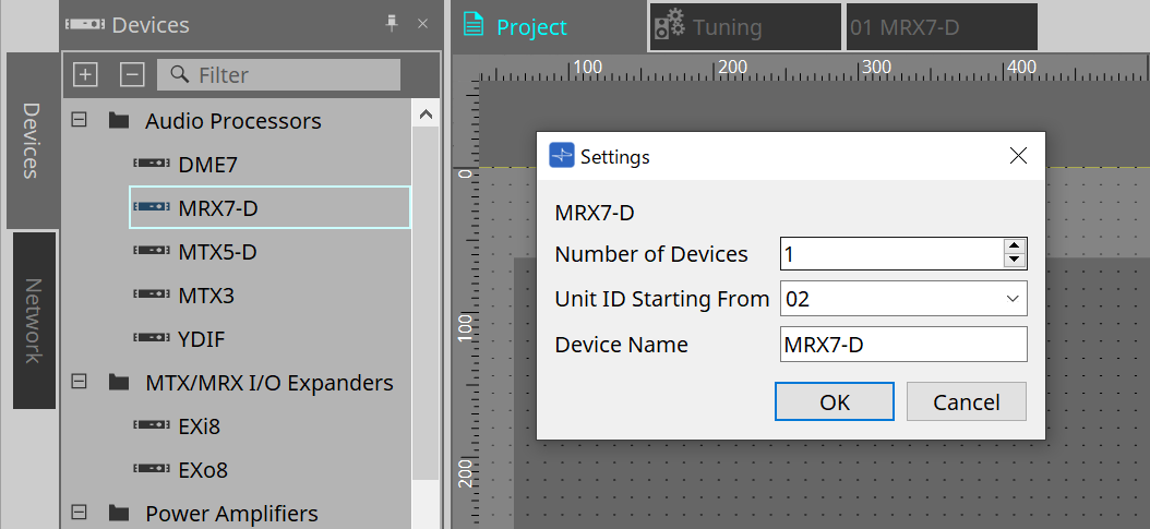
-
Number of Devices
Selects the number of MRX7-D units to be placed on the sheet. -
Unit ID Starting From
The starting number for the device Unit IDs can be selected. -
Device Name
The device name can be displayed and edited.
14.2.1. Toolbar
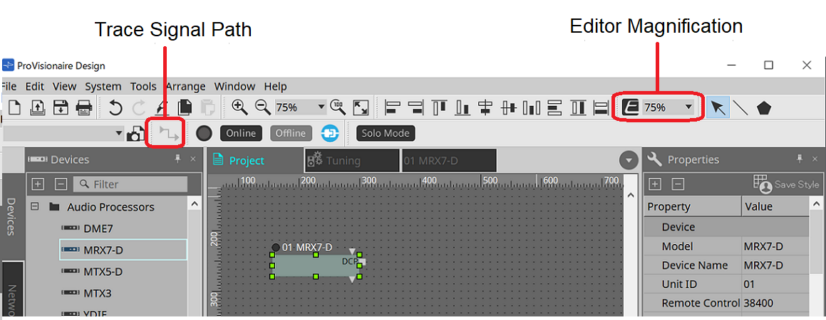
-
Editor Magnification
Changes the magnification of the component editor. -
Trace Signal Path
When this is turned on, when a port or wire is selected, the signal path will be searched in the output and input directions starting from the selected point.
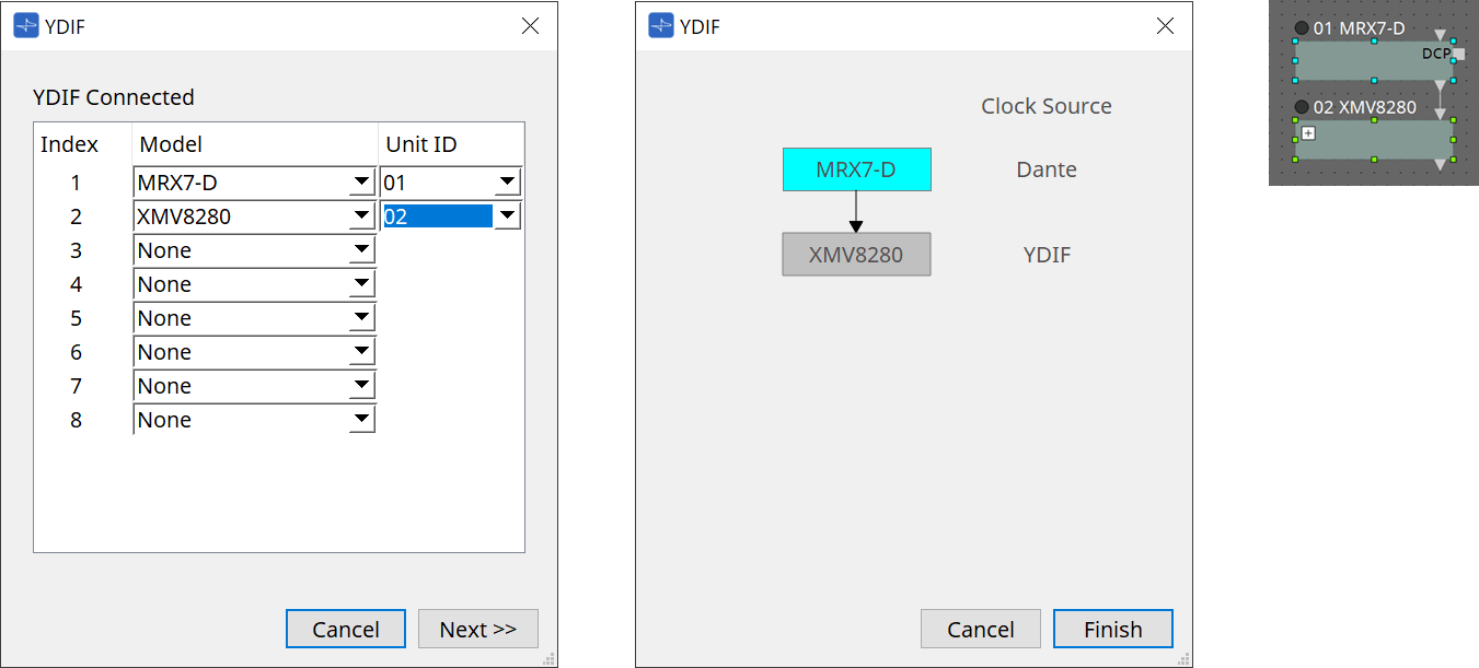
14.2.2. Devices Area
If "YDIF" is added to the project, an example of connecting multiple devices by YDIF terminals is displayed.
The word clock setting is also performed automatically.
14.2.3. Properties Area
Displays/edits the MRX7-D information.
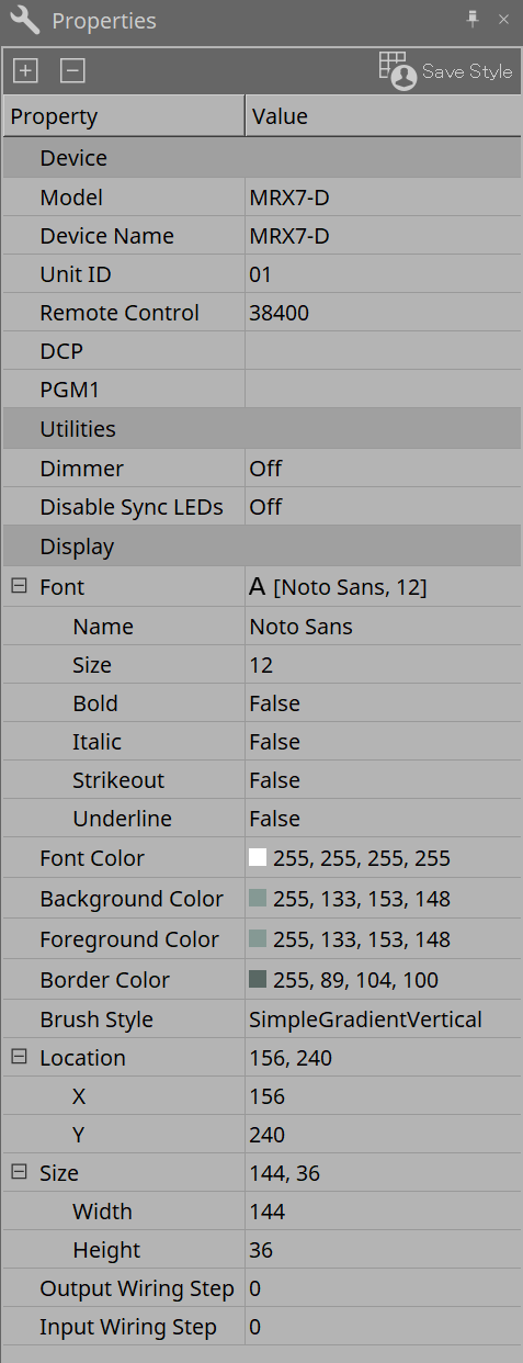
Device
-
Unit ID
Match this to the Unit ID of the MRX7-D main unit. The factory default setting is 1. -
Remote control
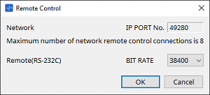
Confirm the port number when connecting an external controller, and configure the settings when connecting an external controller to RS-232C.
The Remote Control dialog is displayed from the that is displayed when the Value field in Properties is clicked.
-
[Network IP PORT No.]
Displays the port number of the MRX7-D’s NETWORK terminal.
Up to 8 external controllers can be connected to the terminals.
-
-
[Remote (RS-232C) BIT RATE] List Box
Selects the RS-232C communication speed. 38400 bps or 115200 bps can be selected.
One external controller can be connected to the RS-232C connector. -
[OK] Button
Saves the settings and closes the dialog. -
[Cancel] Button
Closes the dialog without changing the settings.-
DCP
Selects the DCP to be connected to the MRX7-D DCP port.
When a DCP is selected, that DCP is connected to the MRX7-D and the DCP component is added to the device sheet.
-
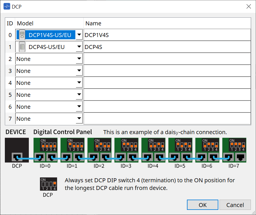
Parameter assignments are performed in the DCP component editor .
-
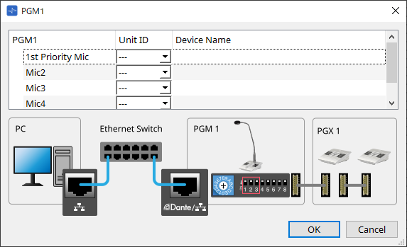
PGM1
Specifies the Unit ID for the PGM1 that is controlling the MRX7-D.
The PGM1 dialog is displayed from the
that is displayed when the Value field in Properties is clicked.
For details, refer to the MTX5-D Paging setting flow .
|
The MRX7-D retains the PGM1 settings data, so there is no problem with the configuration even if PGM1 is not discovered in ProVisionaire Design.
When updating the PGM1’s firmware or changing the IP address, please install Bonjour Print Service and allow ProVisionaire Design to discover the device. |
For other items, please check the explanation displayed when the Properties item is selected.
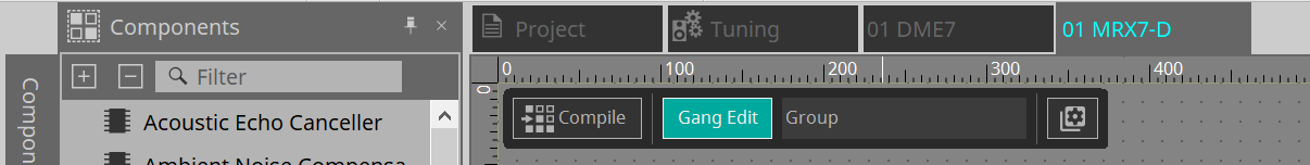
14.3. Device Sheet Screen Configuration

①
Tool buttons
Buttons have been made for the commands frequently used on the MRX7-D
(Tool buttons)
.
②
Components Area
A list of the components is displayed
(Components Area)
.
③
Parameter Sets Area
Configures the parameter sets and snapshots
(Parameter Sets Area)
.
④
Presets Area
Configures presets
(Presets Area)
.
Presets can be recalled from the main unit’s front panel.
⑤
Parameter Link Group Area
Creates a parameter link group to link multiple parameters for Level-type or for ON/OFF-type
(Parameter Link Group Area)
.
⑥
Gang Edit Group Area
Creates a gang edit group that links multiple components
(Gang Edit Group Area)
.
⑦
Design Sheet
This is a sheet for placing and connecting components
(Design Sheet)
.
⑧
Properties Area
Changes the settings of the selected component, port, or wire
(Properties Area)
.
⑨
Parameters Area
Displays a list of the components and parameters already placed on the design sheet
(Parameters Area)
.
⑩
Bird’s Eye View
Displays a full view of the sheet.
⑪
Components
Various signal processing modules such as equalizers and compressors are called "components."
⑫
Component Editor
Parameters are set or configured in the Component Editor.
14.5. Tool Buttons
These are shortcut buttons for commands that are used frequently on the MRX7-D.
| Button | Command | Overview |
|---|---|---|
|
|
Analyzes whether there are any problems with component placement or wiring. |
|
|
|
Turns the Active button in the Gang Edit Group area on or off.
|
|
|
|
[Tools] |
[Remote Control Setup List]
|
14.6. Components Area
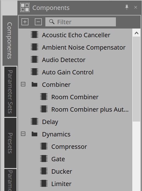
For components specific to the MRX7-D, please refer to the
omponent editor
.
For details about components common to other DMEs, refer to the
「ProVisionaire Design Component Guide
.
14.7. Design Sheet
Refer to the DME10/7 Design Sheet .
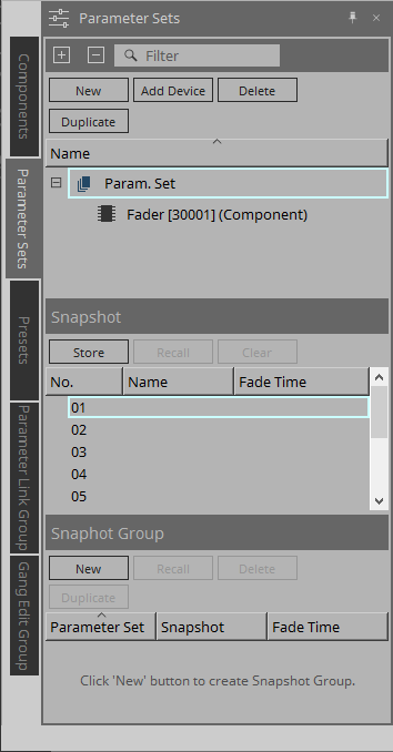
14.9. Parameter Sets Area
A collection of parameters being stored/recalled in a snapshot is called a parameter set. By storing a snapshot, the current values of parameter set members are saved. A single parameter set can store 10 snapshot patterns. A single parameter can be registered to multiple parameter sets.
Snapshots can be controlled using an external controller by assigning them to the Remote Control Setup List.
Note that snapshots cannot be recalled from the front panel of the main unit (only presets can be recalled).
In the Presets area, click on [Recall Settings] to register the snapshot to a preset.
The following methods are available for registering to a parameter set.
| Registration Source | Registration Method |
|---|---|
|
Design Sheet |
While holding the < Ctrl > key down, drag & drop the component into the Parameter Set name. |
|
Right-click on the component and select the parameter set to be registered using [Add to Parameter Set]. |
|
|
Component Editor |
While holding the < Ctrl > key down, drag & drop the parameter into the Parameter Set name. |
|
Link Control Editor |
While holding the < Ctrl > key down, drag & drop the Link Control into the Parameter Set name. |
|
Parameters Area*1 |
Drag & drop a component or parameter into the Parameter Set name. |
|
Right-click on the component or parameter and select the parameter set to be registered using [Add to Parameter Set]. |
|
|
Parameter Sets Area |
After selecting the parameter set to register, click the [Add Device] button to register all components placed at that point in time. |
*1. Multiple components and parameters can be registered to a parameter set simultaneously by pressing < Shift > and < Ctrl > together.
For explanations of Parameter Sets and Snapshots, refer to the DME10/7 Parameter Sets Area .
14.9.1. Snapshot Group
Multiple snapshots can be registered in a single group and recalled all at once.
Snapshot groups can be controlled using an external controller by assigning them to the Remote Control Setup List.
Note that snapshot groups cannot be recalled from the front panel of the main unit (only presets can be recalled).
In the Presets area, click on [Recall Settings] to register the snapshot group to a preset.
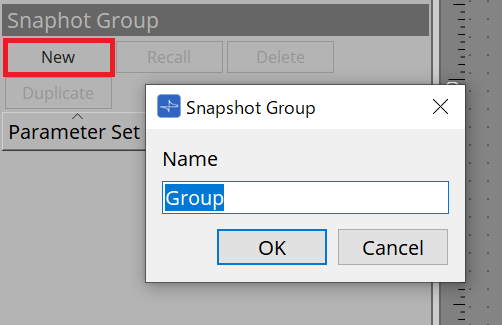
14.9.2. Steps to create a snapshot group
-
Click the [New] button to create a group.
-
Assign snapshots to a Group by using drag & drop.
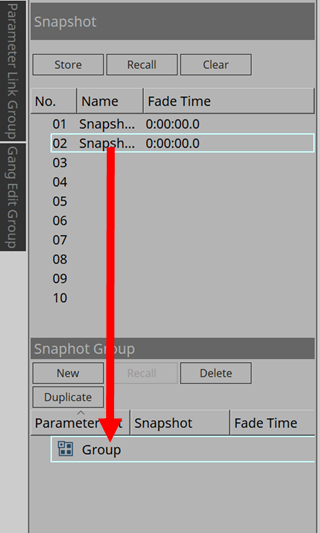
Unstored snapshots can also be assigned.
-
Rearrange the order of the snapshots as needed.
Snapshots registered in a Group are recalled in order from the top.
By right-clicking a snapshot, the context menu will be displayed, which allows you to rearrange the order of the snapshots.Menu Details Delete
Deletes the selected snapshot.
Up
Moves the selected snapshot up one level.
Down
Moves the selected snapshot down one level.
If you want to delete a Group or snapshot, select the Group or snapshot and click the [Delete] button. You can also delete by using the computer’s Delete key, or selecting [Delete] from the context menu.
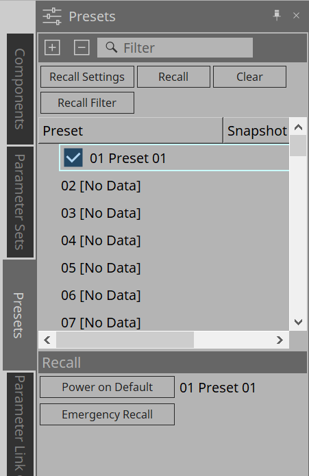
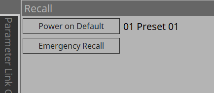
14.10. Presets Area
Snapshots and snapshot groups cannot be recalled directly from the front panel of the main unit.
Presets can be recalled from the front panel of the main unit.
Register snapshots and snapshot groups to presets.
-
Snapshot
The snapshots associated with the preset will be displayed in the [Recall Settings] dialog. -
Enable Scheduler
When this is on and the preset is recalled, the scheduler function will be enabled.
Click the icon to turn this on/off.
| When the scheduler function is disabled, the [SCHEDULER] indicator on the main unit will flash rapidly when an event is occurring. |
-
Filter
In the Recall Filter dialog, if even one part has been set that will not recalled, a will be displayed.
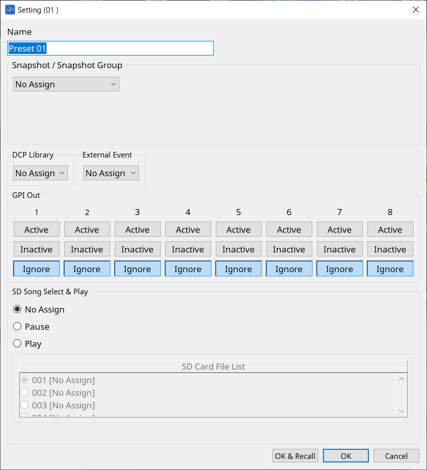
14.10.1. Procedure
-
Select a preset.
-
Click the [Recall Settings] button.
-
In the Recall Settings dialog, select the Snapshot or Snapshot Group Recall to be assigned to the preset in Snapshot/Snapshot Group.
-
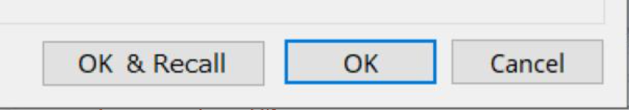
[OK & Recall] Button
Confirms the current settings, performs a Recall, and closes the dialog. -
[OK] Button
Confirms the settings and closes the dialog. -
[Cancel] Button
Discards the changes and closes the dialog.For GPI Out and SD Song Select & Play, refer to the DME10/7 Recall Settings dialog .
For an explanation of Recall, refer to the DME10/7 Parameter Sets Area .
|
How to collectively recall all parameters of the MRX7-D
To collectively recall all parameters of the MRX7-D, register a snapshot of ParameterSets configured on the MRX7-D device to the presets. 1. Create ParameterSets. 2. Register the MRX7-D using Add Device. 3. Create a snapshot. 4. Register the snapshot created in step 3 to the presets. |
14.11. Parameter Link Group Area
Creates a parameter link group to link multiple parameters for Level-type or for ON/OFF-type.
A single parameter can be registered in multiple parameter link groups. The created parameter link group can be used in Snapshot, Scheduler, GPI, DCP, MCP1, or the Remote Control Setup List. Level-type and ON/OFF-type cannot be mixed in a single parameter link group. Up to 64 parameter link groups can be created.
The following methods are available for registering to a parameter link group.
[Parameter]
| Registration Source | Registration Method |
|---|---|
|
Component Editor |
While holding the |
|
Right-click the parameter and select the parameter link group to register in [Add to Parameter Link Group]. |
|
|
Parameters Area*1 |
Drag & drop the parameter into the parameter link group in the Parameter Link Group area. |
|
Right-click the parameter and select the parameter link group to register in [Add to Parameter Link Group]. |
*1. Multiple parameters can be registered to a parameter link group simultaneously by pressing < Shift > and < Ctrl > together.
| Pressing any letter key while selecting a parameter link group or other item in the Parameter Link Group area will select the parameter link group or other item with the matching first letter. |
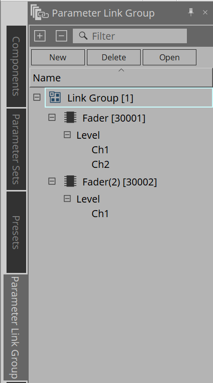
-
[New] Button
Creates a parameter link group. -
[Delete] Button
Deletes the selected parameter link group or parameter. -
[Open] Button
Displays the Link Control editor for the selected parameter link group.
14.11.1. Link Control Editor
There is a link control for each parameter link group. When a link control is changed, the parameters registered in the parameter link group are also changed at the same time.
Even if the parameters registered in the parameter link group are changed, the link control parameters do not change.
Link control can be assigned to GPI/DCP/Remote Control Setup List/Parameter Link Group/MCP1.
The name of the parameter link group is displayed in the title bar.
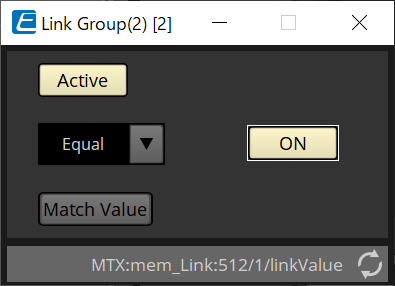
| Level-type | ON/OFF-type |
|---|---|
|
|
|
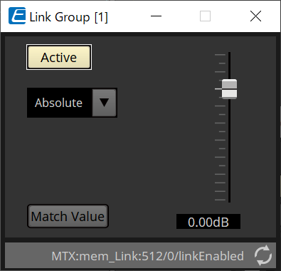
-
Fader (level-type only)
Sets values for level-type parameters. -
[ON] Button (ON/OFF-type only)
Sets values for on/off-type parameters. -
[Match Values] Button
If [Absolute] or [Equal] is selected in the combo box, the value of the registered parameter will be the same as the value of the link control. -
[Active] Button
If this is on, the parameter link group is enabled. Turn this off if you want to temporarily disable the link. -
Combo Box
Set how the level-type and ON/OFF-type settings are applied.
|
[Absolute]/[Equal] |
Sets the value of the registered parameter to the same value as the link control. |
|
[Relative]/[Opposite] |
When you operate the link control, the registered parameters will move while maintaining their relative positions. |
14.12. Gang Edit Group Area
Creates a gang edit group that links multiple components.
Parameters for components of the same type within a group can be changed at the same time. Because this can be done even while online, you can use it to make final adjustments to the Speaker Processor (or others) while listening to the sound at the actual location.
When you open the component editor for one of the components you want to change, it becomes a link control and you can configure other linked components.
Up to 64 gang edit groups can be created.
The following methods are available to register to the Gang Edit Group.
| Registration Source | Registration Method |
|---|---|
|
Design Sheet |
While holding the < Ctrl > key down, drag & drop the component into the gang edit group name. |
|
Right-click on the component and select the gang edit group to be registered using [Add to Gang Edit Group]. |
|
|
Parameters Area*1 |
Drag & drop the component into the gang edit group name.
|
*1. Multiple components can be registered to a gang edit group simultaneously by pressing < Shift > and < Ctrl > together.
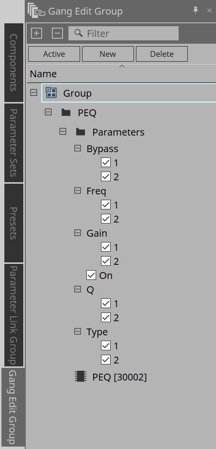
-
[Active] Button
Enables/disables the gang edit group function. Applies to the currently selected group.
-
[New] Button
Creates a gang edit group. -
[Delete] Button
Deletes the selected gang edit group or component. -
[Parameters]
Put a check in the checkbox for the parameter to be linked.
14.12.1. Procedure
-
Click the [New] button to create a group.
-
While holding the < Ctrl > key down, drag & drop the component on the sheet into the group name.
Or drag & drop the component from the Parameters area.
Linking only works with components of the same type, but multiple types of components can be registered. -
Uncheck the parameters you do not want to link.
-
Turn the [Active] button or the [Gang Edit] button in the toolbar ON.
-
Double-click a component on any sheet registered in the gang edit group.
The component editor will be displayed. -
Change the parameters in the component editor.
The parameters for components of the same type that belong to the gang edit group will be changed in tandem. -
If the [Active] button or the [Gang Edit] button in the toolbar are turned OFF, linking will be disabled.
14.13. Properties Area
Changes the settings of the currently selected component, port, or wire.
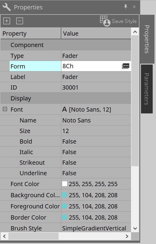
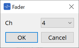
-
Component
Click the
that is displayed when you click the "Form" value. A dialog is displayed that allows you to change the number of channels for the component.
When MY4-AEC or MY8-AE96S is selected for the Slot component, you can edit the Sampling Rate Converter.
For details, refer to the
Sampling Rate Converter dialog box
of the MTX5-D.
-
Port
Click the
that is displayed when you click the "Label" value. A dialog is displayed that allows you to edit the labels of all the component ports at once.
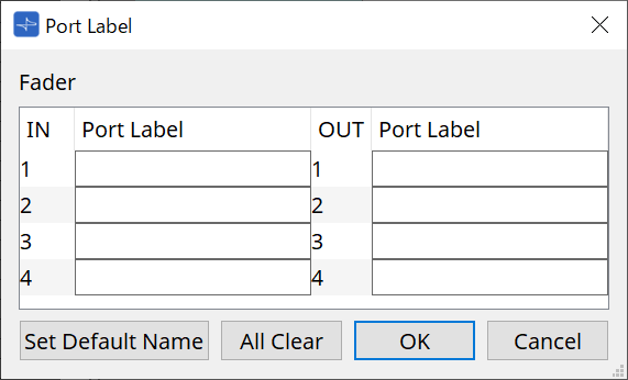
For details, refer to Port Label dialog .
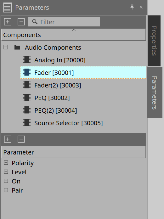
14.14. Parameters Area
Displays information about the component currently selected on the design sheet.
The parameters of the component currently selected in the upper area are listed in the lower area.
From this area, you can assign components and parameters to parameter sets, remote control setup lists, GPI dialogs, DCP components, and the MCP1 editor. For assignment methods, refer to the explanation for each screen.
14.16. Dialog
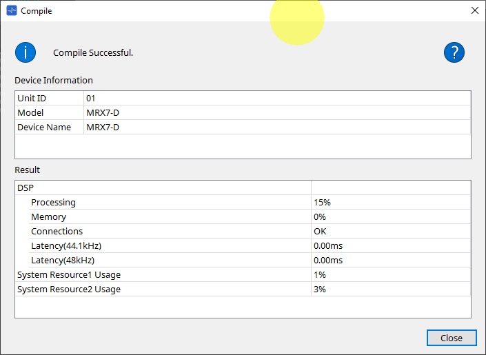
14.16.1. Compile Dialog
Click the tool button [Compile] on the device sheet to open this dialog.
Analyzes whether there are any problems with the placement or wiring of the MRX7-D components. It can also check resource consumption, etc.
-
 /Message
Displays whether the compile action was successful or failed. If it was successful, the message "Completed normally. " is displayed. If it failed, a message saying "Compile failed" is displayed. -
 Button
Click to display the method for resolving the problem. -
[Result]
Displays the compiled results. The MRX-7D can go online only when the compile has succeeded.
For each item, check the Information that opens when you click on ?.
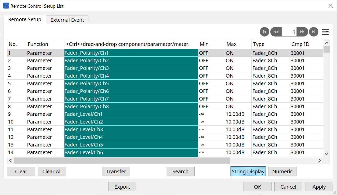
14.16.2. Remote Control Setup List Dialog
Click [Remote Control Setup List] from the [Tools] button in the device sheet to open this dialog.
The MRX7-D can be controlled from an external device using the Dante [PRIMARY]/[SECONDARY] terminal or the [RS-232C] terminal.
To control or monitor from an external device, parameters, meters, snapshots, and snapshot groups must be registered in the Remote Control Setup List.
| Configure the external device according to the "MTX3 MTX5-D MRX7-D XMV Series EXi8 EXo8 Remote Control Protocol Specifications." |
● Remote Setup Tab
Two methods are available for registering to the list.
| Registration Source | Registration Method |
|---|---|
|
Design Sheet |
While holding the < Ctrl > key down, drag & drop the component into the list. |
|
Right-click the component and select [Add to Remote Control List]. |
|
|
Component Editor/
|
[Parameters]
|
|
[Components]
|
|
|
Parameters Area*1 |
Drag & drop components or parameters into the list.
|
|
Parameter Sets Area |
Drag & drop snapshots into the list.
|
|
Parameter Link Group Editor |
While holding the < Ctrl > key down, drag & drop LINK Control into the green area. |
*1. Multiple components and parameters can be registered to the list simultaneously by pressing < Shift > and < Ctrl > together.
-
[Function]
Displays the types of items registered in the list. -
[< Ctrl >+drag-and-drop component/parameter/meter.]
Displays the items registered in the list. -
[Type]
Displays the type of component that has parameters registered in the list. -
[Cmp ID]
Displays the ID of a component that has parameters registered in the list. -
[MIN]/[MAX]
Displays the upper and lower limits and selection range for the parameters registered in the list. In the case of Level-type parameters for which a Min/
Max value can be configured, clicking this will open a dialog box where you can specify the range. -
Transfer Button
Starts the File Transfer application , which is used to send files to ProVisionaire Touch.
For other functions, refer to the DME10/7 Remote Control Setup List dialog .
● External Event Tab
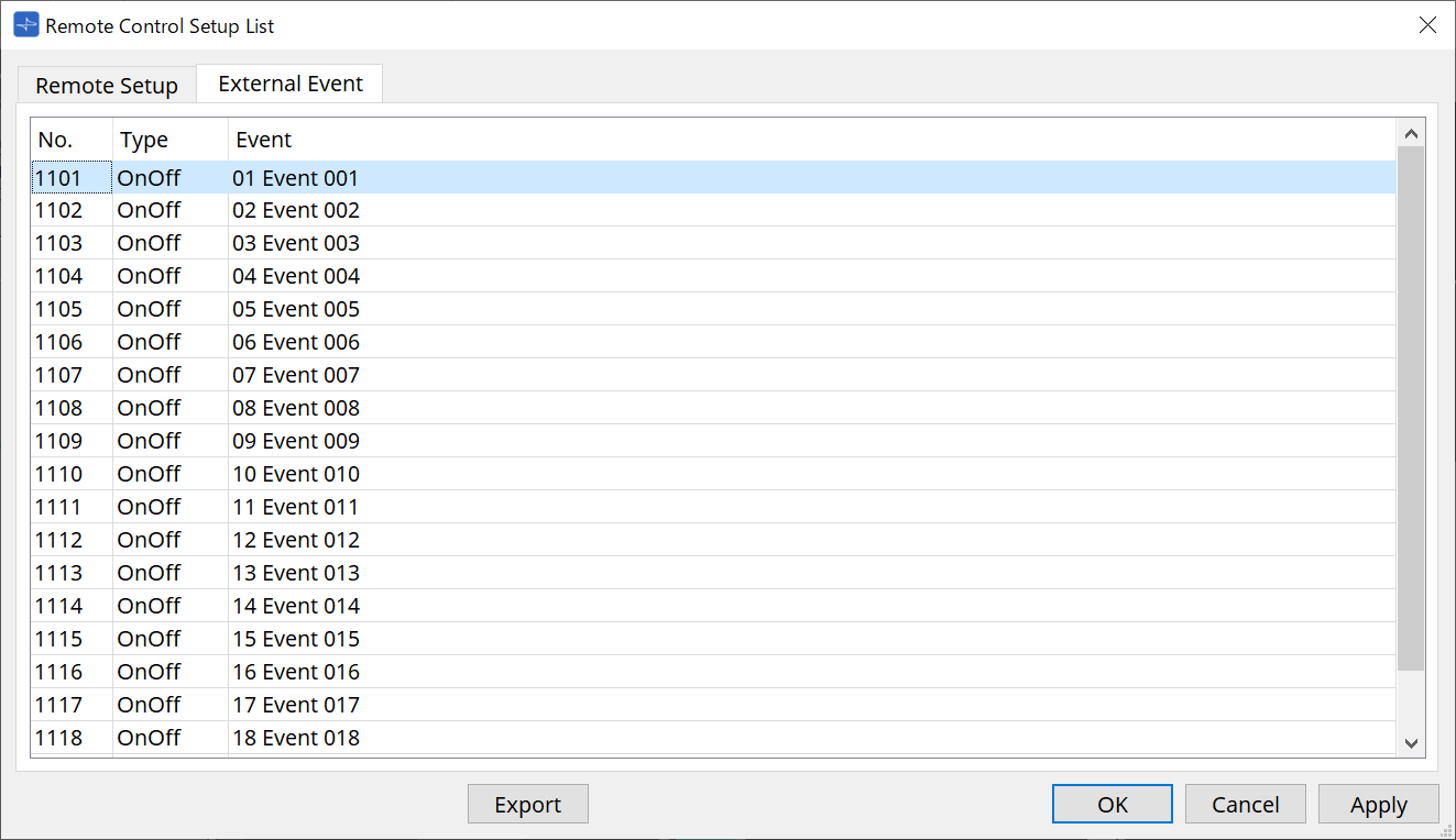
External Events are registered under the initial state of the list.
For details about External Events, refer to the MTX5-D/MTX3 External Events dialog .
14.16.3. File Transfer Application
Click the Transfer button in the Remote Control Setup List dialog to open this dialog.
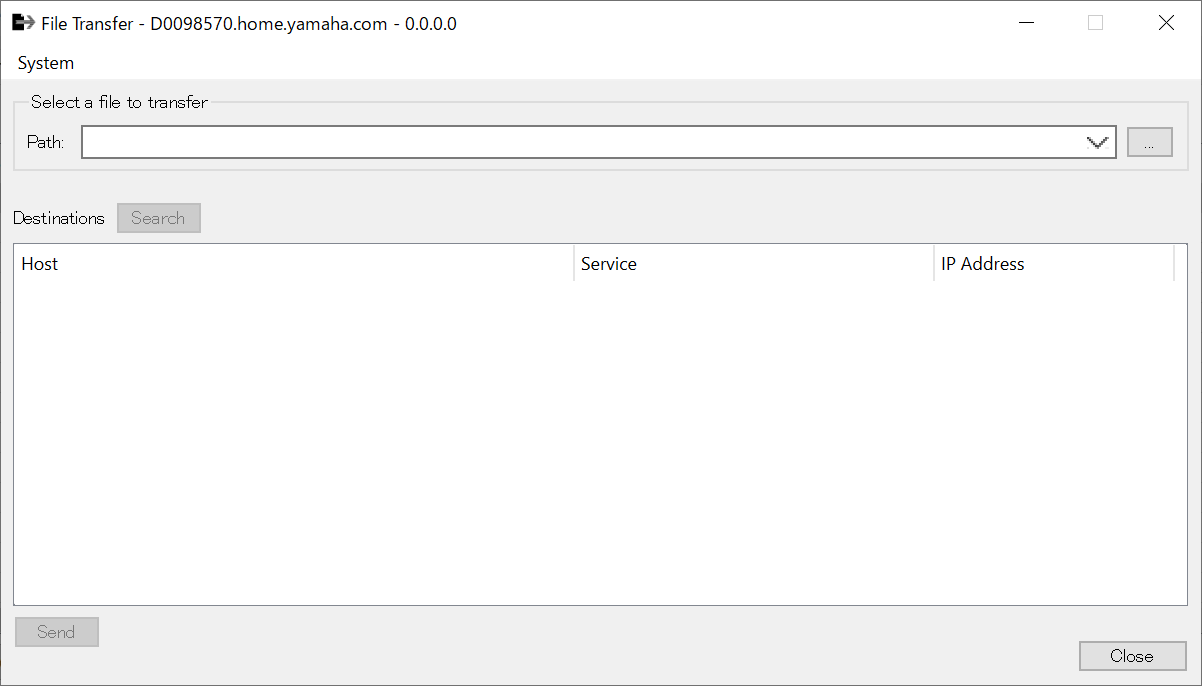
This transfers the exported .rcsl file, PDF file, image file, etc. to an iPad on the same network that has ProVisionaire Touch (V1.2 or later) installed.
Before transferring, start ProVisionaire Touch and confirm that it is displayed on the screen.
If no network adapter has been selected, the [Network Setup] dialog will be displayed for you to select a network adapter.
The file extensions that ProVisionaire Touch can receive are as follows.
.rcsl, .pdf, .jpg, .jpeg, .bmp, .png, .pvt, .ypvt, .ypvk
.pvt, .ypvt, and .ypvk files are saved in the Provisionaire Touch file folder.
.rcsl files can be used by registering the MRX7-D as a device with Provisionaire Touch.
-
System Menu
Launch the Network Setup dialog from the Network Setup command. -
Select a file to transfer
Selects the file to be sent. Clicking the button on the right side displays the Open File dialog, which allows you to select a file.
-
Destinations
Select the transfer destination iPad. If you don’t see the transfer destination iPad, press the [Search] button to search your network. The [Search] button is enabled when a file to be transferred has been selected. -
[Send] Button
Sends the selected file(s) to the selected iPad. -
[Close] Button
Closes the File Transfer application.
14.16.4. SD Card File Manager Dialog
Click the [Tools] button on the device sheet and then click [SD Card File Manager] to open this dialog.
Refer to the DME10/7
SD Card File Manager dialog
.
14.16.5. Scheduler Dialog
Click the [Tools] button on the device sheet and then click [Scheduler] to open this dialog.
Refer to the MTX5-D/MTX3
Scheduler dialog
.
14.16.6. GPI Dialog
Click the [Tools] button on the device sheet and then click [GPI] to open this dialog.
Refer to the DME10/7
GPI dialog
.
|
The MRX7-D does not have GPI settings on the control layer.
The MRX7-D does not have a Control Type: Direct Parameter Value setting. |
The following methods are available for registering parameters, snapshots, snapshot groups, and presets.
| Registration Source | Registration Method |
|---|---|
|
Parameter Sets Area |
Drag & drop snapshots and snapshot groups into the green area. |
|
Presets Area |
Drag & drop presets into the green area. |
|
Component Editor |
While holding the < Ctrl > key down, drag & drop the parameter into the green area. |
|
Parameters Area |
Drag & drop the parameter into the green area. |
|
Parameter Link Group Editor |
While holding the < Ctrl > key down, drag & drop LINK Control into the green area. |
14.16.7. External Events Dialog
Click the [Tools] button on the device sheet and then click [External Events] to open this dialog.
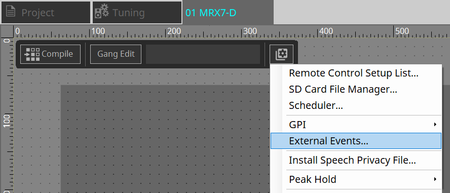
Refer to the MTX5-D/MTX3 External Events dialog .
14.16.8. Install Speech Privacy File Dialog
Click the [Tools] button on the device sheet and then click [Install Speech Privacy File] to open this dialog.
Installs the files related to the Speech Privacy component to the MRX7-D.
Once the installation is complete, the MRX7-D will restart.
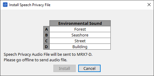
-
[Install] Button
Starts the installation of files to the MRX7-D. -
[Cancel] Button
Closes the dialog without installing any files.
14.17. Component Editor
This section explains the component editor specific to the MRX7-D.
For details about components common to other DMEs, refer to the
"ProVisionaire Design Component Guide"
.
List of MRX7-D components
|
"Components" area folder
Folder |
component name | Link |
|---|---|---|
|
--- |
Acoustic Echo Canceller |
|
|
--- |
Ambient Noise Compensator |
|
|
--- |
Audio Detector |
|
|
--- |
Auto Gain Control |
|
|
Combiner |
Room Combiner
|
|
|
--- |
Delay |
|
|
Dynamics |
Compressor
|
|
|
--- |
Effect |
|
|
EQ |
GEQ
|
|
|
--- |
Fader |
|
|
Feedback Suppressor |
Notch FBS
|
|
|
Filter |
BPF
|
|
|
Input/Output |
Analog In |
|
|
Dante In |
||
|
Stereo In |
--- |
|
|
YDIF In |
--- |
|
|
Analog Out |
||
|
Dante Out |
||
|
YDIF Out |
--- |
|
|
SD Card |
||
|
Slot |
||
|
--- |
Meter |
|
|
Mixer |
Dalay Matrix
|
|
|
--- |
Oscillator |
|
|
--- |
Paging |
|
|
--- |
Polarity |
|
|
--- |
Router |
|
|
--- |
Source Selector |
|
|
--- |
Speaker Processor |
|
|
--- |
Speech Privacy |
14.17.1. Acoustic Echo Canceller Component Editor
Acoustic Echo Canceller (AEC) is a function that eliminates echoes caused by speaker reflections and wall reflections (acoustic echoes), as well as constant noise from air conditioners, etc., all of which are problems during teleconferences. By delivering clear audio that eliminates echoes and noise to the other party, smooth conversations can be achieved during the teleconference.
Note that to eliminate the acoustic echo generated on the other party’s side, a system with an acoustic echo canceller function must also be installed at their end.
Each MRX7-D can be equipped with AECs for up to 8 channels.
The following delay amount is added to the signal path where the AEC component has been placed.
When the word clock is 44.1kHz
: 26.17msec
When the word clock is 48kHz
: 24.02msec
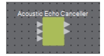
The AEC inputs are as follows, from top to bottom.
-
MicIn 1 : Input from microphone
-
MicIn 2 : Input from microphone
-
Reference : Input of a signal that you do not want to send to a remote location (a signal to be considered an echo and removed) (e.g., Codec In)
| MicIn 1 and MicIn 2 should be inputs from microphones in the same conference room. |
■ AEC Editor
This configures the AEC-related settings. The left side of the screen is for settings related to the microphone connected to MicIn 1, and the right side of the screen is for settings for the microphone connected to MicIn 2.

①
AEC [ON] Button
Enables or disables the AEC function.
②
[NR] Button
Turns the noise reduction function on/off, to eliminate constant noise from nearby projectors, air conditioners, etc. It is recommended that this normally be turned on.
③
[THRESHOLD] Knob
When using noise reduction, any noise that exceeds the Threshold level is attenuated to the level set as the Threshold.
④
Level Meter
Displays the information related to input/output and acoustic echo.
-
[IN] Level Meter
Displays the input level from the microphone. -
[REF] Level Meter
Displays the input level from Reference. -
[OUT] Level Meter
Displays the output level from the AEC. -
[ERL] Level Meter
Displays the ratio between the Reference input and the Amount of echo included in the microphone input as estimated by the AEC.
A good installation environment is one in which ERL (Echo Return Loss) is between 0 dB and –16 dB. If it is greater than 0 dB, the input level of the microphone may be too high or the microphone and speaker may be too close. If it is lower than –16 dB, the microphone’s input level may be too low. -
[ERLE] Level Meter
Displays the amount (in dB) of acoustic echo that the AEC has removed from the microphone input as a result of learning. If the echo is removed correctly, a negative value will be displayed. -
[TER] Level Meter
Displays the amount (in dB) of acoustic echo ultimately removed.
⑤
[RESET] Button
The information learned by AEC is resent when this is clicked.
⑥
Port Text Box
Displays the port name. The name can be changed by double-clicking.
14.17.2. [Effect] Component Editor

①
EFFECT [ON] Button
Enables or disables the effect function.
②
Effect Type List Box
Selects the effect type. There are four types that can be selected.
-
Reverb Hall
This is a reverb that simulates a large space such as a concert hall. -
Reverb Stage
This is a reverb that simulates a wide stage. -
Karaoke Echo
This is a microphone echo intended for use in karaoke. -
Vocal Echo
This is an echo that is designed specifically for vocals and is intended for use on stage.
③
Effect Parameter Knob
Adjusts one effect parameter. If the effect type is Reverb, this will be [REVERB TIME], and if it is Echo, this will be [DELAY TIME].
14.17.3. Analog In Component Editor
Displays settings related to the HA (head amp) for the [INPUT] terminal and the level of the input audio signal.

①
Channel Index
Displays the analog input terminal number.
②
Level Meter
Displays the analog input level.
③
[GAIN] Knob
Adjusts the HA (head amp) analog gain.
④
[+48V] Button
Switches the HA phantom power supply (+48 V) ON and OFF.
![]() NOTE
NOTE
If the phantom power supply is not required, turn this button OFF.
If the phantom power supply is turned ON, please note the following to prevent damage or noise to the main device/external devices.
• When connecting a device that is not phantom power compatible to an [INPUT] terminal, turn the button OFF.
• Do not disconnect cables from the [INPUT] terminal while the power button is still ON.
• Set the output level to its lowest level when turning the phantom power supply off or on.
There is no +48 V Active switch. Use settings that match the connected equipment to avoid damage.
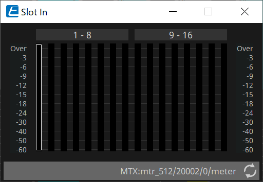
14.17.4. Slot In Component Editor
Displays the audio signal level being input from the Mini-YGDAI card.
14.17.5. Analog Out Component Editor
Displays the settings related to the [OUTPUT] terminal output and the level of the audio signal being output.

①
Channel Index
Displays the analog output terminal number.
②
Level Meter
Displays the analog output level.
③
[GAIN] Knob
Adjusts the output gain.
④
[INV] Button
Switches the output signal polarity.
14.17.6. Slot Out Component Editor
Displays the settings related to the Mini-YGDAI card output and the level of the audio signal being output.

①
Channel Index
Displays the output terminal number.
②
Level Meter
Displays the output level.
③
[GAIN] Knob
Adjusts the output gain.
④
[INV] Button
Switches the output signal polarity.
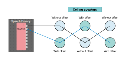
14.17.7. Speech Privacy Component Editor
This function mixes environmental sounds and disturbance sounds to make it difficult for people around you to hear conversations in a particular location.
Only one can be installed for each MRX7-D.
Two mixed signals are output for each system, one without offset and one with offset that offsets the playback point. By alternating the speakers that output each of these, discomfort caused by phase shift in areas where audio overlaps is reduced.
Before putting the MRX7-D online, use the
Install Speech Privacy File dialog
that is displayed when you select [Install Speech Privacy File] from the [Tools] button to install the files to the MRX7-D.
Configure settings related to environmental sounds and disturbance sounds in the Speech Privacy component editor.

①
System Index
Displays the number for the system to be configured.
②
[Environmental Sound] List Box
Sets the environmental sound to be used. Select to match the output environment.
-
Forest : Forest sounds
-
Seashore : The sound of waves
-
Street : Street sounds
-
Building : Air conditioning sounds
③
[Speech Sound Masker] Knob
Sets the percentage of disturbance sound to be included in the output audio. The unit is %.
④
[LEVEL] Knob
Sets the signal level for the mix of environmental sounds and disturbance sounds.
⑤
[ON] Button
Mutes or unmutes the mixed signals of each system.
14.18. Alert List
Refer to the MTX5-D/MTX3 Alert List .
14.19. Flow of Paging Configuration
For the MRX7-D, to use PGM1, first place the Paging component from the Components area on the device sheet.
For the setting method, refer to the MTX5-D
Flow for paging settings
.